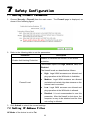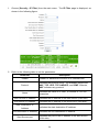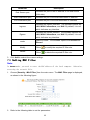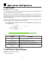
1
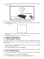
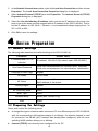
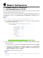
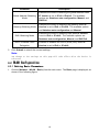
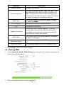
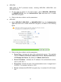
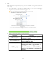
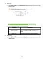
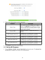
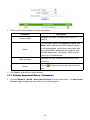
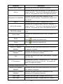
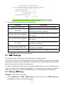
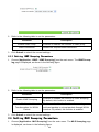
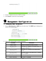
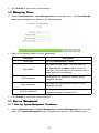
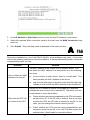
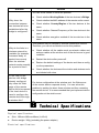
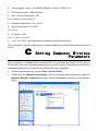
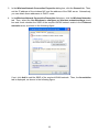
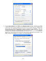
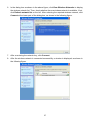
ZXV10 W811N
Indoor Wireless Access Point
User Manual
Version: 1.0
ZTE CORPORATION
NO. 55, Hi-tech Road South, ShenZhen, P.R.China
Postcode: 518057
Tel: (86) 755 26771900
Fax: (86) 755 26770801
URL: http://ensupport.zte.com.cn
E-mail: [email protected]
1
LEGAL INFORMATION
Copyright © 2012 ZTE CORPORATION.
The contents of this document are protected by copyright laws and international treaties. Any reproduction or distribution of this document or any portion of this document, in any form by any means,
without the prior written consent of ZTE CORPORATION is prohibited. Additionally, the contents of
this document are protected by contractual confidentiality obligations.
All company, brand and product names are trade or service marks, or registered trade or service
marks, of ZTE CORPORATION or of their respective owners.
This document is provided “as is”, and all express, implied, or statutory warranties, representations
or conditions are disclaimed, including without limitation any implied warranty of merchantability,
fitness for a particular purpose, title or non-infringement. ZTE CORPORATION and its licensors shall
not be liable for damages resulting from the use of or reliance on the information contained herein.
ZTE CORPORATION or its licensors may have current or pending intellectual property rights or applications covering the subject matter of this document. Except as expressly provided in any written
license between ZTE CORPORATION and its licensee, the user of this document shall not acquire any
license to the subject matter herein.
ZTE CORPORATION reserves the right to upgrade or make technical change to this product without
further notice.
Users may visit ZTE technical support website http://ensupport.zte.com.cn to inquire related information.
The ultimate right to interpret this product resides in ZTE CORPORATION.
Revision History
Revision No.
Revision Date
Revision Reason
R1.0
2012–09–26
First Edition
Serial No. SJ-20121010104831-004
Publishing Date: 2012–09–26
2
Contents
1 Safety Precautions ............................................... 5
2 Product Introduction ............................................. 6
2.1 Product Overview................................................................................. 6
2.2 Typical Applications .............................................................................. 6
2.3 Indicator Status Description .................................................................... 6
2.4 Interface Description ............................................................................. 7
3 Product Installation ............................................. 7
3.1 Installation Requirements ....................................................................... 7
3.2 Product Installation ............................................................................... 8
3.3 Computer Configuration ......................................................................... 9
4 Device Preparation ............................................... 10
4.1 Default Settings ................................................................................... 10
4.2 Preparing for Settings............................................................................ 10
4.3 Logging in to the System ........................................................................ 11
5 Device Status .................................................... 12
5.1 Viewing Device Information ..................................................................... 12
5.2 Network Interface Information Viewing ....................................................... 12
5.3 Viewing WLAN Interface Information ......................................................... 12
6 Network Configuration ............................................ 13
6.1 Broadband Connection Configuration ........................................................ 13
6.2 WLAN Configuration ............................................................................. 16
6.3 Address Management ........................................................................... 29
6.4 Setting Static Routing Parameters ............................................................ 31
6.5 Enabling IPv6...................................................................................... 32
7 Safety Configuration ............................................. 33
7.1 Setting Firewall Parameters .................................................................... 33
7.2 Setting IP Address Filter......................................................................... 33
7.3 Setting MAC Filter ................................................................................ 35
7.4 Setting ALG Switch............................................................................... 36
8 Application Configuration ........................................ 37
8.1 Setting UPnP ...................................................................................... 37
8.2 Setting Device Naming Parameters ........................................................... 37
8.3 QoS Settings ...................................................................................... 38
8.4 Setting Time Management Parameters....................................................... 42
8.5 IGMP Settings ..................................................................................... 43
3
8.6 Setting MLD Snooping Parameters ........................................................... 44
9 Management Configuration ......................................... 45
9.1 Managing SNMP Parameters .................................................................. 45
9.2 Managing Users .................................................................................. 46
9.3 Device Management ............................................................................. 46
9.4 Setting Log Management Parameters ........................................................ 48
9.5 AP Management .................................................................................. 49
9.6 Setting Ping Diagnosis Parameters ........................................................... 50
A FAQ .............................................................. 51
B Technical Specifications ......................................... 53
C Setting Computer Wireless Parameters ............................. 54
4
1
Safety Precautions
Installation
l
Use the default power adapter accompanying the equipment. Otherwise, the equipment
may be damaged or not be functioning properly.
l
Pay close attention to the load of the power socket or power cable. The overloaded power
socket or damaged power cable/connector may trigger electric shock or fire. Check relevant cables periodically and replace the damaged cables immediately.
l
Ensure proper heat dissipation space to prevent this product and relevant accessories from
overheat-caused issues. Do not block the heat dissipation holes with any objects.
l
Keep this product away from heat sources, high temperature, or sunlight.
l
Keep this product away from damp or moisture places.
l
Do not put this product onto an unstable surface.
Usage
l
When you are not using this product or want to clean it, power off this product and remove
power cables. Pay attention to the power adapter surface where the temperature may be
high.
l
Wait at least 15s between two equipment startups.
l
Protect this product from damages caused by lightning or abrupt increase of the current or
voltage. Remove the power cable if this product is to be unused for a long period of time.
Service
Do not disassemble this product without authorization; otherwise, the warranty of this product
will become ineffective. Contact your service provider when any of the following occurs on this
product:
l
The power cable or connector is damaged.
l
Certain liquid falls into this product accidentally.
l
This product is soaked with rain or other liquid.
l
This product cannot work even when no operation instructions are violated.
l
The shell of this product is damaged after fallen down or seriously struck.
l
The indicators of this product are working abnormally.
5
2
Product Introduction
2.1 Product Overview
ZTE broadband wireless access product works at 2.4 GHz band, and accords with the IEEE
802.11b, 802.11g, and 802.11n standards. It adopts the Orthogonal Frequency Division Multiplexing (OFDM) technology and provides the data transmission rate of 300 Mbps maximally.
The product can be applied in the mobile, telecom industry and enterprises. It is featured by
powerful functions such as high transfer rate, high receiving sensitivity, and long transmission
distance, and can provide powerful solution to basic telecom operators, ISP and industry enterprises. It supports several security encryption mechanism and access rights control functions,
and provides strong protection to WLAN. Besides, it supports power supply to the equipment
through the POE mode.
2.2 Typical Applications
l
Medium- and small-sized enterprises where mobile office is achieved by wireless coverage
l
Remote access to enterprise networks
This product supports multiple functions such as email, file transfer, terminal emulation, is
applicable to various wireless network connection modes (including point-to-point (P2P),
single-access, multi-access, and roaming), and flexibly adapts to diverse applications (including intra-LAN connection and inter-network connection).
l
Places where network connections are difficult
This product can work in places such as old buildings or asbestos buildings where routing
cables is difficult.
l
Mobile office systems
This product can be used by retailers and manufacturers or at other places that are often
changed.
l
Temporary LANs for special projects
This product is applicable to temporary LANs at business exhibitions, exhibition halls, or
construction fields, when the retailers or the flight/shipping companies need to expand
space during peak hours, or when audit personnel needs to create customer working
groups.
l
Access to the database by workers on the move
This product can be used by doctors, nurses, or retailers to access the database for information exchange.
l
Home office users
This product can help home office users easily and quickly set up a small PC network.
2.3 Indicator Status Description
The following table describes the indicators of the ZXV10 W811N.
6
Name
Status
Blinking
Status
Description
The device is starting up, upgrading software, or
detecting an error during self-check.
Off
The device works normally.
On
The device is powered on.
Off
The device is powered off or is faulty.
On
The device enables the WLAN function normally.
Power
WLAN
Eth
Blinking
The device is transmitting data.
Off
The device does not enable the WLAN function or is
faulty.
On
The device is successfully connected to the
10M/100M/1000M Ethernet port.
Blinking
Off
The device is transmitting data.
The device fails to connect to the Ethernet port or is
faulty.
2.4 Interface Description
ZXV10 W811NThe interfaces and buttons are described in the table as below.
Interface Name
3
Description
Power
Power interface, connected to the original power adapter
accompanying the device
Reset
Reset button; in power-up running status, keep pressing the
button for over 5s, and the current configuration will be reset as
factory-leaving configuration. The system will restart automatically
Ethernet
Ethernet interface, connected to the network port of computer or
other network equipment through the RJ-45 network wire
COM
Console port, connecting the computer and the Console port;
Baud rate is 115200. It supports the user to manage and debug
equipments through the Console mode (not suggested for normal
users)
Product Installation
3.1 Installation Requirements
Before the device is installed and used, the following requirements must be met:
7
l
A computer equipped with a 10M/100M/1000M Base-TX adaptive fast Ethernet NIC is available.
l
The IP address of the Ethernet NIC is in the same network segment as the IP address of the
device, for example, 192.168.0.1. The default IP address of the device is 192.168.0.228.
l
It is recommended that you use the browser of the Microsoft IE 6.0 or a later version and
disable the proxy service of the browser.
l
Two network cables used for connecting devices are available.
3.2 Product Installation
l
The product supports direct power supply through the standard external power adapter, as
shown in the figure below.
l
If the switch does not support PoE power supply, the product supports 48V power supply
over Ethernet through the standard PoE module, as shown in the figure below.
8
l
The product supports direct power supply through the standard PoE switch, as shown in
the figure below.
ZXV10 W811NFollow the steps below to mount the product on the wall.
1. Press the positioning paperboard against the wall to be mounted with the device, as shown
in the figure below.
2. Hammer in screws (expansion bolts are suggested) at the position of the three holes in the
paperboard.
3. Remove the paperboard, and then mount the device on the wall.
3.3 Computer Configuration
3.3.1 Checking Computer Settings
First, disable the proxy service. It is recommended to shut down the VPN software and related
firewall software on the current computer. The following considers Microsoft Internet Explorer
as an example.
1. In an IE window, choose [Tools→Internet Options] from the main menu. The Internet
Options dialog box is displayed.
2. Click the Connections tab and click LAN Settings.
3. In the dialog box that is displayed, clear the Use a proxy server check box and click OK.
3.3.2 Setting TCP/IP Parameters
This manual considers Windows XP as an example to describe how to set TCP/IP parameters.
1. On the Windows task bar, choose [Start→Control Panel].
2. In the Control Panel window, double-click the Network Connections icon.
9
3. In the Network Connections window, right-click Local Area Connection and then choose
Properties. The Local Area Connection Properties dialog box is displayed.
4. Select Internet Protocol (TCP/IP) and click Properties. The Internet Protocol (TCP/IP)
Properties dialog box is displayed.
5. Select the Use the following IP address option and set the IP address of the local computer to be in the same network segment as the IP address of the ZXV10 W811N. That is,
set the IP address to 192.168.0.x. Wherein, x is a hexadecimal integer ranging from 1 to
227 or 229 to 254.
6. Click OK to save the settings.
4
Device Preparation
4.1 Default Settings
The following table describes the default settings of the ZXV10 W811N.
Parameter
IP Address/Mask of ETH
Interface
User Name/Password
Language of Web Page
Default Value
IP address: 192.168.0.228; subnet mask: 255.255.255.0
Initial user name/password for common users: user/user;
initial user name/password for administrators: admin/admin
English
AP Mode
Fit AP mode
AP Name
APxxxxxxxxxxxx; Wherein, xxxxxxxxxxxx indicates the
MAC address of the device.
Country/Region
Default
AC Discovery Mode
DHCP
WAN Type
DHCP
Wireless Mode
SSID
Mixed (802.11b+802.11g)
SSID1
4.2 Preparing for Settings
Check and confirm the following points:
l
A straight-through or crossover cable connects a PC to an Ethernet port on ZXV10 W811N,
with the corresponding LAN interface always on or blinking. If a wireless network is used
for connection, the WLAN (Wi-Fi) network has already been configured, with the corresponding WAN interface always on or blinking.
l
Internet (TCP/IP) has correctly been configured for the PC.
10
l
The settings of the agent server for the browser such as IE have been disabled.
l
Certain data has been provided by the service provider (for details of the data, contact the
service provider).
4.3 Logging in to the System
The ZXV10 W811N supports setting parameters based on Web. You can set and manage the
ZXV10 W811N through a Web browser.
The Web page of the ZXV10 W811N supports both Chinese and English languages. By default,
the system provides Web pages in English.
1. In the address bar of the IE browser, enter http://192.168.0.228 (default IP address of the
Eth interface of the ZXV10 W811N), and then press Enter. A login dialog box is displayed,
as shown in the following figure.
Note:
Enter, the system displays a dialog
After you enter the IP address and then press Enter
box indicating that the IE will access an insecure network. In this case, click
Yes to display the login dialog box.
2. (Optional) Click 中 文 or English at the upper right corner of the login dialog box to switch
the display language.
3. Enter the user name and password, and click Login. The Web page of the ZXV10 W811N
is displayed.
Note:
user. Common
The initial user name and password for common users are user and user
users only have the rights to view the device status. The initial user name and
admin. Administrators have the rights
password for administrators are admin and admin
to set and manage the ZXV10 W811N through the IE browser.
l
Click Logout at the upper right corner to log out the current user and return to the login
dialog box.
l
Click
l
Click the Help at the upper part. On the Help page, view the required help topic.
l
Click
at the lower left corner to view the help topics related to the current page.
at the upper left corner to switch the display language.
11
5
Device Status
5.1 Viewing Device Information
1. Choose [Status→Device Information] from the main menu. The Device Information
page is displayed.
2. View the device information, including device model, device SN, batch number, hardware
version, software version, BOOT version, and AP name.
5.2 Network Interface Information Viewing
5.2.1 Viewing Ethernet Interface Information
1. Choose [Status→Network Interface→Ethernet] from the main menu. The Ethernet page
is displayed.
2. View the information of Ethernet interface, including interface name, MAC address, status,
mode, received packets/bytes, and transmitted packets/bytes.
Note:
Click Refresh refresh the current settings of the device.
5.2.2 Viewing Network Connection Information
1. Choose [Status→Network Interface→WAN Connection] from the main menu. The WAN
Connection page is displayed.
2. View the connection information, including connection type, WAN MAC address, NAT, IP
address, DNS, gateway, connection status, and remaining lease time.
Note:
Click Refresh refresh the current settings of the device.
5.3 Viewing WLAN Interface Information
1. Choose [Status→User Interface→WLAN Interface information] from the main menu.
The page is displayed.
2. On the page, view the WLAN interface information, including status of wireless network
connection, channel, SSID name, authentication mode, encryption mode, MAC address,
received packets/bytes, transmitted packets/bytes, received/transmitted error packets, and
packet loss during packet receive and transmission.
Note:
Click Refresh refresh the current settings of the device.
12
6
Network Configuration
6.1 Broadband Connection Configuration
6.1.1 Setting Broadband Connection (Fat AP)
The wireless AP ZXV10 W811N supports two working modes: fat AP mode and fit AP mode.
By default, the ZXV10 W811N works in fit AP mode.
To change the AP mode of the ZXV10 W811N, log in to the Web page of the ZXV10 W811N as
the administrator and then choose [Administration→AP Management→AP Mode] from the
main menu.
Note:
After the AP mode is switched, the device will automatically restart.
1. Choose [Network→WAN→WAN Connection] from the main menu. A page is displayed,
as shown in the following figure.
2. Refer to the above table to set the parameters. For details, refer to Setting Broadband
Connection (Fit AP).
l
Working Mode: The available options are Bridge and Router. By default, it is Bridge.
l
WAN Type: When IP Version is set to IPv4, the available options are DHCP, Static,
and PPPoE. When IP Version is set to IPv6 or IPv4/v6, the available options are
DHCP and PPPoE. By default, it is DHCP.
3. Click Submit to submit the current settings.
Note:
Any change to the settings on this page will take effect after the device is
restarted.
13
6.1.2 Setting Broadband Connection (Fit AP)
AP Mode of the device is set to Fit.
1. Choose [Network→WAN→WAN Connection] from the main menu. A page is displayed,
as shown in the following figure.
2. Refer to the following table to set the parameters.
Parameter
Description
IP Version
Indicates the version of the IP protocol. The available
options are IPv4, IPv6, and IPv4/v6. By default, it is IPv4.
AC Discovery Mode
Indicates the AC discovery mode. The available options
are DHCP, Static, DNS, and Broadcast. By default, it
is DHCP.
AC Name
Indicate the AC name. This parameter is required when
AC Discovery Mode is set to DHCP or DNS.
Enable CAPWAP
Encryption
WAN Type
Enable Verify AC
Enables or disables CAPWAP encryption.
Indicates the WAN type. When IP Version is set to
IPv4, the available options are DHCP, Static, and
PPPoE. When IP Version is set to IPv6 or IPv4/v6, the
available options are DHCP and PPPoE. By default, it is
DHCP. When AC Discovery Mode is set to DHCP, this
parameter is set to DHCP.
By default, this function is enabled.
14
Parameter
Description
Enable VLAN
Enables or disables the function of WLAN configuration.
The WLAN ID and 802.1p are used to specify the VLAN
and priority of the device.
VLAN ID
802.1p
Enable DSCP
DSCP
Indicates the VLAN tag of data packets transmitted
through the WAN interface. It ranges from 0 to 4094.
Indicates the processing priority. It ranges from 0 to 7 and
is applicable only to multi-WAN connections. By default,
it is 0. The value 0 indicates that the priority is not set. In
this case, the greater the value, the higher the priority.
Enables or disables the differential services code point
(DSCP) function for data streams.
Indicates the DSCP value. It ranges from 0 to 63.
MTU
Indicates the maximum transmission unit. By default, it is
1448.
Wireless Switch IP(1–4)
Indicates the IP address of the connected wireless switch
when AC Discovery Mode is set to Static.
Wireless Switch IPv6
( 1–4 )
Indicates the IPv6 address of the connected wireless
switch when IP Version is set to IPv6 or IPv4/v6 and AC
Discovery Mode is set to Static.
Wireless Switch Name
( 1–4 )
Indicates the name of the connected wireless switch
when AC Discovery Mode is set to DNS.
Username/Password
Indicates the user name and password of the PPPoE
connection when WAN Type is set to PPPoE.
Authentication Type
Indicates the authentication type when WAN Type is set
to PPPoE. The available options are Auto, Password
Authentication Protocol (PAP), and Challenge
Handshake Authentication Protocol (CHAP). This
parameter is determined by carriers according to BAS.
IP Address/Mask
Indicates the IP address and mask of the static connection
when WAN Type is set to Static.
Default Gateway
Indicates the default gateway address of the static
connection when WAN Type is set to Static.
DNS(1–3)
Indicates the DNS of the static connection when WAN
Type is set to Static.
15
Parameter
Description
Global Address Obtaining
Mode
Indicates the mode of obtaining the global address when
IP Version is set to IPv6 or IPv4/v6. The available
options are Stateless auto-configuration, Manual, and
DHCPv6.
Gateway Obtaining Mode
Indicates the mode of obtaining the gateway when IP
Version is set to IPv6 or IPv4/v6. The available options
are Stateless auto-configuration and Manual.
DNS Obtaining Mode
Indicates the mode of obtaining DNS when IP Version
is set to IPv6 or IPv4/v6. The available options are
Stateless auto-configuration, Manual, and DHCPv6.
DHCP Enabled Prefix
Delegation
Enables or disables the DHCP prefix proxy when IP
Version is set to IPv6 or IPv4/v6.
3. Click Submit to submit the current settings.
Note:
Any change to the settings on this page will take effect after the device is
restarted.
6.2 WLAN Configuration
6.2.1 Setting Basic Parameters
1. Choose [Network→WLAN→Basic] from the main menu. The Basic page is displayed, as
shown in the following figure.
16
2. Refer to the following table to set the parameters.
Parameter
Enable Wireless RF
Enable Isolation
Description
Enables or disables the function of WLAN RF.
Enables or disables the function of SSID isolation. By
default, this function is disabled.
Mode
The available options are IEEE 802.11b Only, IEEE
802.11g Only, IEEE 802.11n Only, Mixed(802.11b+802
.11g), and Mixed(802.11b+802.11g+802.11n).
Country/Region
Indicates the country or region. Set this parameter
according to the actual condition. By default, it is China.
Channel
Selects the required channel according to country code.
The available options are Auto or a value ranging from
1 to 13. By default, it is Auto. The channel used for
communication between a wireless AP and a wireless
site is determined by the local management environment.
All the sites that communicate with the ZXV10 W811N
must have the same channel.
Total Maximum Clients
Indicates the maximum number of access users allowed.
It ranges from 1 to 560.
17
Parameter
Beacon Interval
Transmitting Power
QoS Type
RTS Threshold
DTIM
Fragment Threshold
Description
By default, it is 100 ms.
The available options are Auto, 100%, 90%, 80%, 70%,
60%, 50%, 40%, 30%, 20%, and 10%. By default, it is
100%. The power level refers to the percentage of the
output power to the maximum power. Usually, the higher
the power, the longer the transmission distance.
The available options are Disabled, WMM, and SSID.
By default, it is WMM.
Indicates the threshold of sending requests.
Indicates the DTIM interval.
Indicates the size of wireless fragment. It is a limit
to packet size. If the size of a data packet exceeds
the threshold, the packet will be fragmented and then
transmitted with multiple data packets.
WIDS Mode
The available options are Access, Monitor, and Mixed.
By default, it is Access.
WIDS Scan Period
Indicates the scanning period of WIDS. By default, it is
120.
WIDS Scan Mode
This parameter ranges from 0 to 13. By default, it is 0.
3. Click Submit to submit the current settings.
6.2.2 Setting SSID
1. Choose [Network→WLAN→SSID Settings] from the main menu. A page is displayed, as
shown in the following figure.
2. Refer to the following table to set the parameters.
18
Parameter
Choose SSID
Hide SSID
Enable SSID
Enable SSID Isolation
Description
Indicates the SSID. It ranges from SSID1 to SSID16.
Hides the SSID.
Enables or disables the SSID.
Enables or disables the internal isolation function of
SSID.
Isolation Mode
Indicates the isolation mode. The available options are
Unicast, Broadcast, Multicast, and All. By default, it
is All.
Maximum Clients
Indicates the maximum number of access users
allowed by SSID. It ranges from 1 to 560. By default, it
is 32.
SSID Name
Indicates the name of the SSID. It consists of 1 to 32
characters.
Priority
Indicates the priority of the SSID. It ranges from 0 to
7. By default, it is 0. The value 0 indicates that the
priority is not set. In this case, the greater the value,
the higher the priority.
VLAN ID
Indicates the VLAN tag of data packets transmitted
through the interface. It ranges from 0 to 4094.
As Management SSID
Disabled by default; configure this SSID whether the
SSID used by the management device.
3. Click Submit to submit the current settings.
6.2.3 Setting Security Parameters
1. Choose [Network→WLAN→Security] from the main menu. On the page that is displayed,
set Authentication Type to WPA-PSK.
19
2. Refer to the following table to set the parameters.
Parameter
Description
Choose SSID
Indicates the SSID. It ranges from SSID1 to SSID16.
Authentication Type
Indicates the authentication type. The available
options are Open System (not encrypted), Shared
Key, Open System & Shared Key, WPA-PSK,
WPA2-PSK, WPA/WPA2-PSK, WPA-EAP,
WPA2-EAP, WPA/WPA2-EAP, WAPI-PSK, and
WAPI-CERT.
WPA Passphrase
Indicates the WPA encryption key. It consists of 8 to
63 characters.
Enable WPA Group Key
Update
Enables or disables the key update function of WPA
group. By default, this function is enabled.
WPAGroup Key Update
Interval
Indicates the interval of key upgrade. By default, it
is 600s.
WPA Encryption Algorithm
Indicates the WPA encryption algorithm. The available
options are AES, TKIP, and TKIP+AES.
The available options of Authentication Type are Open System, WPA-PSK, WPA-EAP,
WEP, WAPI-PSK, and WAPI-CERT.
l
If Authentication Type is set to Open System, it indicates no encryption.
20
l
WPA-PSK
WPA refers to Wi-Fi protected access, including WPA-PSK, WPA2-PSK, and
WPA/WPA2-PSK.
a. On the page as shown in the above figure, select WPA-PSK, WPA2-PSK,
or WPA/WPA2-PSK from the Authentication Type drop-down list to enable
WPA-PSK encryption.
b. Refer to the above table to set the parameters.
l
WPA-EAP
a. Select WPA-EAP, WPA2-EAP, or WPA/WPA2-EAP from the Authentication
Type drop-down list to enable WPA-EAP encryption, as shown in the following
figure.
b. Refer to the above table to set the parameters.
à
Server Type: Indicates the type of the authentication server. The available
options are Master Auth Server, Master Acct Server, Backup Auth Server,
and Backup Acct Server. By default, it is Master Auth Server.
à
Server IP Address: Indicates the IP address of the authentication server,
such as 192.168.1.1.
à
Server Port: Indicates the port of the authentication server. It ranges from 0
to 65535. For example, the port is 1812.
à
Secret: Indicates the WPA-EAP encryption key. It consists of 8 to 63 characters.
21
l
WEP
WEP refers to wired equivalent privacy. It is one of WLAN security protocols that are
used widely.
a. Select Shared Key or Open System & Shared Key from the Authentication Type
drop-down list, as shown in the following figure.
b. Refer to the following table to set the parameters.
Parameter
Description
WEP Encryption
Enables or disables WEP encryption. By default,
this function is enabled.
WEP Encryption Level
Indicates the length of WEP key. The available
options are 64bit and 128bit.
WEP Key Index
Indicates the key value.
WEP Key (1-4)
Indicates the key values of WEP encryption. A
64-bit WEP key supports 5 ASCII characters or
10 hexadecimal characters. A 128-bit WEP key
supports 13 ASCII characters or 26 hexadecimal
characters.
22
l
WAPI-PSK
a. Select WAPI-PSK from the Authentication Type drop-down list, as shown in the
following figure.
b. Refer to the following table to set the parameters.
Parameter
l
Description
WAPI Key Mode
Indicates the WAPI key mode. The available
options are ASCII and HEX. By default, it is
ASCII.
WAPI Key
Indicates the key values of WAPI encryption.
WAPI-CERT
a. Select WAPI-CERT from the Authentication Type drop-down list, as shown in the
following figure.
23
b. Set Certificate Server IP and Certificate Server Port.
c.
Click Certificate Uploading. On the page that is displayed, select the required
certificate file and click Upload.
Note:
The types of certificate file include AS, AP, and CA. If the AP and CA
certificates are required, upload the AP certificate first. Otherwise,
upload the AS certificate first.
3. Click Submit to submit the current settings.
6.2.4 Setting Rate Limit
Note:
If the rate limit is set to 0, it indicates that the traffic is not limited.
1. Choose [Network→WLAN→Rate Limit] from the main menu. The Rate Limit page is
displayed, as shown in the following figure.
24
2. Refer to the following table to set the parameters.
Parameter
Description
Control Type
The available options are SSID/STA and MAC. By
default, it is SSID/STA. The switching of control
mode will take effect immediately and the original
control mode is cleared.
Choose SSID
Indicates the SSID. It ranges from SSID1 to
SSID16.
SSID Downlink Rate Limit
It ranges from 0 to 100000 kbps. By default, it is 0,
which indicates that the traffic is not limited.
STA Downlink Rate Limit
It ranges from 0 to 100000 kbps. By default, it is 0,
which indicates that the traffic is not limited.
SSID Uplink Rate Limit
It ranges from 0 to 100000 kbps. By default, it is 0,
which indicates that the traffic is not limited.
STA Uplink Rate Limit
It ranges from 0 to 100000 kbps. By default, it is 0,
which indicates that the traffic is not limited.
3. Click Submit to submit the current settings.
6.2.5 Setting ACL Parameters
1. Choose [Network→WLAN→Access Control list] from the main menu. The Access Control list page is displayed, as shown in the following figure.
25
2. Refer to the following table to set the parameters.
Parameter
Choose SSID
Mode
MAC Address
Delete
Description
Indicates the SSID. It ranges from SSID1 to
SSID16.
The available options are Disabled, Forbid, and
Allow, which indicate that SSID channel control
is not implemented, and device connections with
the required MAC addresses are forbidden and
allowed respectively. By default, SSID channel
control is not implemented.
Indicates the MAC address of the device to be
controlled.
Clicks
item.
to delete the required control channel
3. Click Add to submit the current settings.
6.2.6 Viewing Associated Device Information
1. Choose [Network→WLAN→Associated Devices] from the main menu. The Associated
Devices page is displayed, as shown in the following figure.
26
2. Select the required SSID from the Choose SSID drop-down list. Then, view the details of
the associated devices corresponding to the selected SSID. By default, the system displays
the details of the associated devices corresponding to SSID1.
Note:
Click Refresh refresh the current settings of the device.
6.2.7 Scanning an AP
The required SSID needs to be enabled.
1. Choose [Network→WLAN→AP Scanning] from the main menu. The AP Scanning page
is displayed, as shown in the following figure.
2. Select the required channel from the Channel drop-down list.
Note:
Access.
This page cannot be displayed if the SSID is not enabled or WIDS is set to Access
3. Click Scan. Then, the scanning result is displayed on the page.
27
6.2.8 Setting WMM Parameters
1. Choose [Network→WLAN→WMM] from the main menu. The WMM page is displayed, as
shown in the following figure.
2. Refer to the following table to set the parameters.
Parameter
Choose AC
Description
The available options are VO, VI, BE, and BK.
AIFSN
It ranges from 2 to 15.
ECWMin
It ranges from 0 to 15.
ECWMax
It ranges from 0 to 15.
TXOP
It ranges from 0 to 255.
Qlength
It ranges from 0 to 1000.
SRL
It ranges from 0 to 255.
LRL
It ranges from 0 to 255.
3. Click Submit to submit the current settings.
Anti--Attack Test Parameters
6.2.9 Setting Anti
1. Choose [Network→WLAN→Anti-Attack Test] from the main menu. The Anti-Attack Test
page is displayed, as shown in the following figure.
28
2. Refer to the following table to set the parameters.
Parameter
Description
Enable Flood Attack Detection
Enables or disables the function of flood attack
detection.
Enable Snoof Attack Detection
Enables or disables the function of snooping attack
detection.
Aging Time
Blanklist
Indicates the aging time. By default, it is 0s.
Displays the details of the blacklist.
3. Click Submit to submit the current settings.
6.3 Address Management
6.3.1 Managing Addresses
Note:
The start and end IP addresses of DHCP must be in the LAN IP subnet.
1. Choose [Network→LAN→Address Management] from the main menu. The Address
Management page is displayed, as shown in the following figure.
29
2. Refer to the following table to set the parameters.
Parameter
Description
LAN IP Address
Indicates the IP address of LAN group (interface subnet).
By default, it is 192.168.1.1.
Subnet Mask
Indicates the subnet mask of LAN group.
DHCP Service
The available options are DHCP Server, DHCP Relay,
and Disabled. By default, it is DHCP Server.
DHCP Start IP Address
Indicates the start IP address allocated for the DHCP
server. To change the start IP address or end IP address,
make sure that the address is in the same network
segment as the IP address of the ZXV10 W811N.
DHCP End IP Address
Indicates the end IP address allocated for the DHCP
server. To change the start IP address or end IP address,
make sure that the address is in the same network
segment as the IP address of the ZXV10 W811N.
DNS1-3
Default Gateway
Indicates the IP addresses of the DNS server. Up to
three IP addresses are supported.
Indicates the default gateway. By default, it is
192.168.1.1.
30
Parameter
Description
Indicates the lease time, that is, the time of the DHCP
server in leasing the IP address. The unit is second. By
default, it is 86400s.
Lease Time
Allocated Address
The lease time refers to the time of the client in leasing an
IP address from the IP address pool that supports dyna
mic allocation. When the lease time expires, the server
can lease or require a new IP address through the DHCP
server.
Indicates the allocated addresses. The page displays
the allocated addresses and the basic information of the
devices that use these addresses.
3. Click Submit to submit the current settings.
6.3.2 Managing IPv6 Addresses
1. Choose [Network→LAN→IPv6 Address Management] from the main menu. The IPv6
Address Management page is displayed, as shown in the following figure.
2. Re-configure the IPv6 address of the terminal.
3. Click Submit to submit the current settings.
6.4 Setting Static Routing Parameters
1. Choose [Network→Routing→Static Routing] from the main menu. The Static Routing
page is displayed, as shown in the following figure.
31
2. Refer to the following table to set the parameters.
Parameter
Description
WAN Connection
Selects the required interface.
Network Address
Indicates the destination network address to be
accessed.
Subnet Mask
Gateway
Indicates the subnet mask of the destination network
address to be accessed.
Indicates the gateway (next hop) IP address.
Modify
Clicks
to edit the required static routing rule.
Delete
Clicks
to delete the required static routing rule.
3. Click Add to submit the current settings.
6.5 Enabling IPv6
1. Choose [Network→IPv6 Enable→IPv6 Enable] from the main menu. The IPv6 Enable
page is displayed, as shown in the following figure.
2. Select the IPv6 Enable check box.
3. Click Submit to submit the current settings.
32
7
Safety Configuration
7.1 Setting Firewall Parameters
1. Choose [Security→Firewall] from the main menu. The Firewall page is displayed, as
shown in the following figure.
2. Refer to the following table to set the parameters.
Parameter
Enable Anti-Hacking Protection
Description
Enables or disables the function of anti-attack
protection.
The available options are High, Medium, Low, and
Disabled.
The firewall levels are described as follows:
l
High: Legal WAN accesses are allowed and
ping operation at the WAN side is forbidden.
l
Medium: Legal WAN accesses are allowed
and attacks of certain risky data streams on the
Internet can be avoided.
l
Low: Legal WAN accesses are allowed and
ping operation at the WAN side is allowed.
l
Disabled: It is not recommended to use this
parameter. After the firewall is shut down, the
computer is easy to be attacked and the Inter
net surfing is affected.
Firewall Level
3. Click Submit to submit the current settings.
7.2 Setting IP Address Filter
AP Mode of the device is set to Fat.
33
1. Choose [Security→IP Filter] from the main menu. The IP Filter page is displayed, as
shown in the following figure.
2. Refer to the following table to set the parameters.
Parameter
Description
Enable
Enables or disables the function of IP address filter.
Protocol
Indicates the protocol name. The available options are
ANY, TCP, UDP, TCP ANDUDP, and ICMP. Wherein,
ANY indicates any protocol.
Name
Indicates the name of IP filter. It consists of 1 to 256
characters.
Start Source IP Address
Indicates the IP address of the start source (LAN side).
End Source IP Address
Indicates the IP address of the end source (LAN side).
Start Destination IP
Address
Indicates the start destination IP address.
End Destination IP Address
Indicates the end destination IP address.
Start Source port
Indicates the port of the IP address of the start source
(LAN side).
34
Parameter
End Source port
Description
Indicates the port of the IP address of the end source
(LAN side).
Start Destination port
Indicates the port of the start destination IP address.
End Destination port
Indicates the port of the end destination IP address.
Ingress
Indicates the ingress interface. The available options are
LAN, WAN Connections, and Null. By default, it is null,
which indicates any interface.
Egress
Indicates the egress interface. The available options are
LAN, WAN Connections, and Null. By default, it is null,
which indicates any interface.
mode
Selects a mode. The available options are Access and
Discard.
Modify
Clicks
to modify the required IP filter rule.
Delete
Clicks
to delete the required IP filter rule.
3. Click Add to submit the current settings.
7.3 Setting MAC Filter
Note:
In Access mode, you need to enter the MAC address of the local computer. Otherwise,
accessing the network fails.
1. Choose [Security→MAC Filter] from the main menu. The MAC Filter page is displayed,
as shown in the following figure.
2. Refer to the following table to set the parameters.
35
Parameter
Description
Enable
Enables or disables the function of MAC filter. By
default, this function is disabled.
Mode
Selects a mode. The available options are Access
and Discard.
Type
Selects a type. The available options are Bridge,
Route, and Bridge + Route.
Protocol
Indicates the protocol name. The available options
are IP, ARP, RARP, PPPoE, and All.
Source MAC Address
Indicates the MAC address of the device at the
LAN side.
Destination MAC Address
Indicates the MAC address of the device at the
WAN side.
Modify
Clicks
to modify the required MAC filter rule.
Delete
Clicks
to delete the required MAC filter rule.
3. Click Add to submit the current settings.
7.4 Setting ALG Switch
AP Mode of the device is set to Fat.
1. Choose [Security→ALG] from the main menu. The ALG Switch page is displayed, as
shown in the following figure.
2. Enable or disable the ALG switch as required.
3. Click Submit to submit the current settings.
36
8
Application Configuration
8.1 Setting UPnP
AP Mode of the device is set to Fat.
The universal plug and play (UPnP) supports network connection with zero configuration and
automatic discovery of various network devices.
When the UPnP function is enabled, the devices that support this function are allowed to dynamically access the network, obtain IP addresses, and transmit their performance data. If
the DHCP and DNS servers are available in the network, the devices can automatically obtain
DHCP and DNS services.
A device that supports the UPnP function can automatically get out of the network, which does
not affect the device itself or other devices in the network.
1. Choose [Application→UPnP] from the main menu. The UPnP page is displayed, as shown
in the following figure.
2. Refer to the following table to set the parameters.
Parameter
Enable
WAN Connection
Advertisement Period
Advertisement Time to Live
(in hops)
Description
Enables or disables the UPnP function. By default,
this function is disabled.
Selects the required WAN connection.
Sets the required time. The unit is minute.
Sets the required live time (in hops). For example,
it is 4.
3. Click Submit to submit the current settings.
8.2 Setting Device Naming Parameters
AP Mode of the device is set to Fat.
1. Set a domain name.
37
a. Choose [Application→DNS Service→Domain Name] from the main menu. The Domain Name page is displayed, as shown in the following figure.
b. In the Domain Name text box, enter a domain name, for example, ZTE.
c.
Click Submit to submit the current settings.
2. Set a host name.
a. Choose [Application→DNS Service→Hosts] from the main menu. The Hosts page
is displayed, as shown in the following figure.
b. In the Host Name and IP Address text boxes, enter a host name and the IP address
of the host.
c.
Click Add to submit the current settings.
Note:
The instance contents in gray are dynamically obtained at the DHCP side and
require no operations.
l
Clicks
to edit the host name.
l
Clicks
to delete the host name.
8.3 QoS Settings
When AP Mode of the device is set to Fat, the QoS settings are available.
The quality of service (QoS) refers to the service conventions for message transmission and
sharing among network users. For example, QoS includes allowable time of transmission delay,
minimum degree of distortion of presence, and audio and video synchronization.
38
In the QoS framework, the concept of class of service is introduced to QoS mapping. After
QoS is enabled, the ZXV10 W811N can completely control the data packets in both ingress
and egress directions. For the data packets in the ingress direction, the domain mapping (ToS
and priority) needs to be converted to queue. For the data packets in the egress direction, the
queue needs to be converted to domain mapping.
8.3.1 Setting Basic Parameters of QoS
1. Choose [Application→QoS→Basic] from the main menu. The Basic page is displayed,
as shown in the following figure.
2. Refer to the following table to set the parameters.
Parameter
Enable QoS
Total Upstream Bandwidth
Enable Queue
Management
Description
Enables or disables the QoS function.
Indicates the total upstream bandwidth.
Enables or disables the function of queue management.
By default, this function is disabled.
The available options are SP, DWRR, and SP_DWRR.
Scheduler Algorithm
SP: The packets in the queue are transmitted by strictly
following the priority sequence in descending order. When
the queue of high priority is empty, the packets in the
queue of low priority are transmitted.
DWRR: Indicates dynamic weighted round-robin. In this
mode, scheduling is implemented among queues in turn
to ensure each queue can obtain a period of service time.
Enable DSCP Re-marking
Enables or disables the function of DSCP re-marking. By
default, this function is disabled.
Enable 802.1p Re-marking
Enables or disables the function of 802.1p priority
re-marking. By default, this function is disabled.
3. Click Submit to submit the current settings.
39
8.3.2 Setting Classification Rules
1. Choose [Application→QoS→Classification] from the main menu. The Classification
page is displayed, as shown in the following figure.
2. Refer to the following table to set the parameters.
Parameter
Description
Enable
Enables or disables the function of setting QoS
classification rules.
DevIn
Indicates the ingress interface for receiving packets. The
available options are LAN or existing SSIDs. You can
select only one type of interface.
L2Protocol
Indicates the type of the layer-2 protocol of packets. The
available options are IPv4, IPv6, ARP, and PPPoE.
L3Protocol
Indicates the type of the layer-3 protocol of packets. The
available options are TCP, UDP, and ICMP.
40
Parameter
Source MAC Address
Description
Indicates the source MAC address of packets.
802.1p
Indicates the tag value (user priority) of VLAN packets. It
ranges from 0 to 7. The value 0 indicates that the priority
is not set. The greater the value, the higher the priority.
Destination Port MIN/MAX
Indicates the upper and lower thresholds for the
destination port of packets. This parameter ranges from
0 to 65535.
DSCP
Indicates the DSCP value. It ranges from 0 to 63.
802.1p Re-marking
Indicates the re-marking value of the 802.1p priority. It
ranges from 0 to 7. The value 0 indicates that the priority
is not set. The greater the value, the higher the priority.
DSCP Re-marking
Indicates the value of DSCP re-marking. It ranges from 0
to 63.
Queue Index
Indicates the management queue index. It ranges from
1 to 8.
Modify
Clicks
to modify the required rule.
Delete
Clicks
to delete the required rule.
Proprietary configuration for IPv4
Source IP Address
MIN/MAX
Destination IP Address
MIN/MAX
Indicates the upper and lower thresholds for the source
IP address of packets.
Indicates the upper and lower thresholds for the
destination IP address of packets.
TOS
Indicates the service type field of data packets. It ranges
from 0 to 255.
IP Precedence
Indicates the IP priority. It ranges from 0 to 7. The value
0 indicates that the priority is not set. The greater the
value, the higher the priority.
Proprietary configuration for IPv6
Source IPv6 Address
MIN/MAX
Indicates the upper and lower thresholds for the source
IPv6 address of packets.
Destination IPv6 Address
MIN/MAX
Indicates the upper and lower thresholds for the
destination IPv6 address of packets.
Traffic Class
Indicates the traffic type. It ranges from 0 to 255.
Flow Label
Indicates the flow label. It ranges from 0 to 1048575.
41
3. Click Add to submit the current settings.
8.3.3 Setting Queue Management Parameters
Note:
The default queue management algorithm of the system is SP. Queue 8 is the default
queue and is enabled by default.
1. Choose [Application→QoS→Queue Management] from the main menu. The Queue
Management page is displayed, as shown in the following figure.
2. Refer to the following table to set the parameters.
Parameter
Enable
Queue Index
3. Click
Description
Enables or disables the function of QoS queue
configuration.
Indicates the queue index. It ranges from 1 to 8. By
default, only queue 8 is enabled.
next to the required queue. In the Enable option, set whether to enable the queue.
4. Click Modify to submit the current settings.
8.4 Setting Time Management Parameters
You can synchronize the time from the time server by setting the time management parameters
on the device.
1. Choose [Application→Time Management] from the main menu. The Time Management
page is displayed, as shown in the following figure.
42
2. Refer to the following table to set the parameters.
Parameter
Current Date and Time
Time Zone
Description
Displays the current date and time of the device.
Selects the time zone to which the device belongs
according to the actual condition.
Primary NTP Server Address
Sets the address or domain name of the primary
NTP server.
Second NTP Server Address
Sets the address or domain name of the secondary
NTP server.
Poll Interval
Indicates the interval of synchronizing server time.
By default, it is 86400s.
Enable Daylight Saving Time
Enables or disables the DST function. By default,
this function is disabled.
DSCP
Indicates the DSCP value. It ranges from 0 to 63.
3. Click Submit to submit the current settings.
8.5 IGMP Settings
The multicast supports sending a same data packet to multiple devices.
An IP host uses the Internet Group Management Protocol (IGMP) to report multicast member
information to neighbor routers. Meanwhile, a multicast router uses the IGMP protocol to learn
which hosts belong to the same multicast group.
The device supports the IGMP proxy for processing IGMP packets. After the IGMP proxy is
enabled, a LAN host can request being added to or leaving the multicast group. A multicast
router can act as a proxy to send multicast packets to a multicast group at the WAN side.
8.5.1 Setting IGMP Proxy
AP Mode of the device is set to Fat.
1. Choose [Application→IGMP→IGMP Proxy] from the main menu. The IGMP Proxy page
is displayed, as shown in the following figure.
43
2. Refer to the following table to set the parameters.
Parameter
Enable IGMP Proxy
WAN Connection
Description
Enables or disables the function of IGMP proxy.
Selects the required WAN connection.
3. Click Submit to submit the current settings.
8.5.2 Setting IGMP Snooping Parameters
1. Choose [Application→IGMP→IGMP Snooping] from the main menu. The IGMP Snooping page is displayed, as shown in the following figure.
2. Refer to the following table to set the parameters.
Parameter
Description
Enable IGMP Snooping
Enables or disables the function of IGMP snooping.
By default, this function is enabled.
Enable Multicast to Unicast
Transformation for WLAN
Packet
Enables or disables the function of converting
multicast packets to unicast packets through WLAN
interface. By default, this function is enabled.
3. Click Submit to submit the current settings.
8.6 Setting MLD Snooping Parameters
1. Choose [Application→MLD Snooping] from the main menu. The MLD Snooping page
is displayed, as shown in the following figure.
44
2. Enable or disable the function of MLD snooping.
3. Click Submit to submit the current settings.
9
Management Configuration
9.1 Managing SNMP Parameters
1. Choose [Administration→SNMP] from the main menu. The SNMP page is displayed, as
shown in the following figure.
2. Refer to the following table to set the parameters.
Parameter
Description
Enable SNMP
Enables or disables the SNMP function.
Trap Server IP
Indicates the IP address of the alarm server, for
example, 192.168.1.1.
Trap Server2 IP
Indicates the IP address of the backup alarm
server.
Trap Server Port
Indicates the port of the alarm server. It ranges
from 1 to 65535.
Read Community
By default, it is public.
Read Community
By default, it is private.
45
3. Click Submit to submit the current settings.
9.2 Managing Users
1. Choose [Administration→User Management] from the main menu. The User Management page is displayed, as shown in the following figure.
2. Refer to the following table to set the parameters.
Parameter
Description
User Right
Selects Administrator or User.
User Name
Indicates the user name. The user name of
the administrator is admin, which cannot be
changed. The user name of the common user is
user, which can be changed.
Old Password
Indicates the old password required during
password change.
New Password
Indicates the new password required during
password change.
Confirm Password
Indicates the new password required during
password change for confirmation.
3. Click Submit to submit the current settings.
9.3 Device Management
9.3.1 Setting System Management Parameters
1. Choose [Administration→System Management→System Management] from the main
menu. The System Management page is displayed, as shown in the following figure.
46
2. Soft rest the device or restore the default settings of the device.
l
Click Reboot to restart the device.
l
Click Restore Default to restore the default settings of the device and then restart the
device.
9.3.2 Setting Version Upgrade Parameters
Note:
During software upgrade of the device, pay attention to the prompts displayed on the
page and wait patiently. Do not power off or restart the device. Otherwise, the
device may be damaged.
1. Choose [Administration→System Management→Software Upgrade] from the main
menu. The Software Upgrade page is displayed, as shown in the following figure.
2. Click Browse to select the required software version file.
3. Click Upgrade to upgrade the software version file.
9.3.3 Managing User Settings
1. Choose [Administration→System Management→User Configuration Management]
from the main menu. The User Configuration Management page is displayed, as shown
in the following figure.
47
2. Select the required backup configuration file or import a configuration file.
l
Exporting a configuration file
Click Backup Configuration to back up the configuration file of the device.
l
Importing a configuration file
a. Click Browse to select the required configuration file of the device.
b. Click Restore Configuration to import the configuration file of the device.
Note:
After this operation is performed, the device will automatically restart.
9.3.4 Managing Default Settings
1. Choose [Administration→System Management→Default Configuration Management]
from the main menu. The Default Configuration Management page is displayed, as
shown in the following figure.
2. Select the required backup default configuration file or import a default configuration file.
l
Exporting a default configuration file
Click Backup Configuration to back up the default configuration file of the device.
l
Importing a default configuration file
a. Click Browse to select the required default configuration file of the device.
b. Click Restore Configuration to import the default configuration file of the device.
Note:
After this operation is performed, the device will automatically restart.
9.4 Setting Log Management Parameters
1. Choose [Administration→Log Management] from the main menu. The Log Management page is displayed, as shown in the following figure.
48
2. Refer to the following table to set the parameters.
Parameter
Description
Log Enable
Enables or disables the function of log server
management. By default, this function is disabled.
Log Level
Indicates the log level. The levels from low to high
are Debug, Informational, Notice, Warning, Error,
Critical, Alert, and Emergency. After the log level
is set, only the logs of this level or above are kept.
Enable Remote Log
Enables or disables the function of remote login to
log server. By default, this function is disabled.
Log Server Address
Indicates the IP address of the remote log server.
3. Click Submit. Then, the log information of the corresponding level is displayed on the page.
l
Click Refresh to refresh the current log records.
l
Click Clear Log to clear the current log records.
l
Click Download Log to download the required log records to the local disk.
9.5 AP Management
9.5.1 Setting AP Mode
1. Choose [Administration→AP Management→AP Mode] from the main menu. The AP
Mode page is displayed, as shown in the following figure.
49
2. Select the required AP mode (Fat or Fit). By default, the AP mode is Fit.
Note:
After the AP mode is switched, the device will automatically restart.
3. Click Submit to submit the current settings.
9.5.2 Setting AP Name
1. Choose [Administration→AP Management→AP Name] from the main menu. The AP
Name page is displayed, as shown in the following figure.
2. In the AP Name text box, enter the required AP name.
3. Click Submit to submit the current settings.
9.6 Setting Ping Diagnosis Parameters
1. Choose [Administration→Diagnosis→Ping Diagnosis] from the main menu. The Ping
Diagnosis page is displayed, as shown in the following figure.
50
2. In the IP Address or Host Name text box, enter the host IP address or host name.
3. Select the required WAN connection used by the host from the WAN Connection dropdown list.
4. Click Submit. Then, the ping result is displayed in the lower text box.
A
FAQ
During the installation or use of the ZXV10 W811N, some problems may occur. In this case,
refer to the following solutions to solve the problems. If some problems still persist, contact the
corresponding carrier for help.
Question
Solution
The MAC address is the unique ID of a network device. You
can obtain the MAC address of a network device in the following
two ways.
How to obtain the MAC
address of a device?
l
On the bottom of each device, there is a small label. This
label provides the MAC address of the device.
l
Log in to the Web page of the device and click the basic info
rmation of sets to learn the MAC address of the wireless AP.
Usually, an STA needs to search for available APs and then
authenticate and connect to the required AP. Therefore, you can
do as follows to solve this problem:
l
Check whether the channel supported by the STA is the same
as that of the AP. If the AP uses a channel that is not supp
orted by the STA, the STA fails to search for the AP. In this
case, you can change the channel used by the AP.
l
Check whether the STA uses the same authentication and
encryption mode as the AP. If not, the STA fails to pass the
authentication, which leads to connection failure.
Why does the STP fail
to connect to the AP?
51
Question
Solution
l
Check whether interference of same devices exists. To be
specific, check whether wireless devices exist around. If yes,
power off the devices and check whether the interference is
reduced. Alternatively, you can mask the devices that gener
ate interference or adjust their locations.
l
Check whether interference of other devices exists. To be
specific, check whether interference sources that greatly
affect the working of the device, such as microwave oven
or other high-power (2.4 GHz) devices, exist around. If yes,
power off the devices and check whether the interference is
reduced.
l
Check whether incompatibility problems occur between the
STA and AP. The STA may not comply with the 802.11 proto
col specifications, which leads to the connection failure.
Usually, this problem is caused by environment interference,
aging of the device, or reduced TX power. You can do as follows
to solve this problem:
l
Check the wireless channel. To be specific, choose another
wireless channel to see whether the rate is greatly increased.
l
Check wireless interference. To be specific, check whether
wireless devices exist around. If yes, power off the devices
and check whether the interference is reduced. Alternatively,
you can mask the devices that generate interference or adjust
their locations.
l
Check signal strength. To be specific, check the signal stre
ngth between the STA and AP. If the signal strength is low,
the antenna may be loosened or the output power is reduced
due to aging of the device.
l
Check the NIC. If the the NIC power is low, you can test the
bandwidth near the AP.
Why is the bandwidth
not high after the
connection of wireless
network is established?
52
Question
Solution
You can do as follows to solve this problem:
Why does the
connection between
two devices fail to be
established after the
bridge is configured?
l
Check whether Working Mode of the two devices is Bridge.
l
Check whether the MAC address of the remote end is correct.
l
Check whether Country/Region of the two devices is the
same.
l
Check whether Channel/Frequency of the two devices is the
same.
l
Check whether encryption method of the two devices is the
same.
This problem may be caused by wireless interference around.
Therefore, you can do as follows to solve this problem:
Why do the links in a
wireless network be
unstable (for example,
increased delay or
packet loss occurs)
after the wireless
network works normally
for a period of time?
In the case of two
devices with bridge
already configured,
why does the Web
page of the remote
device fail to be opened
if the local device is
used to configure the
remote device through
a wireless link?
l
Check whether all the cables such as network cables and
antenna cables at the wireline end of the device are in good
condition.
l
Restart the device after power-off.
l
Restore the default settings of the device and then re-config
ure the parameters.
l
Check whether the devices at the wireline and wireless ends
are infected with virus.
For device configuration at the wireless end, the Web server
of the remote device responds slowly. You can solve this
problem by waiting for about three minutes and then restarting
the remote device. It is recommended that you implement device
configuration at the wireline end.
B
Technical Specifications
Physical specifications:
l
Size: 180mm×180mm×49mm (L×W×H)
l
Device weight: 300g (excluding the power adapter)
Electrical specifications:
53
l
Power adapter: Input: 100-240VAC 50/60Hz; Output: 12VDC/1.2A
l
POE power supply: 48VDC/500mA
l
Max. power consumption: 5W
Environmental Requirements:
l
Working temperature: -5℃ to 45℃
l
Working humidity: 5% to 95%
IP degree
l
IP degree: IP30
Certification passed
l
CCCi, CE, Wi-Fi, radio transmission equipment model authorization
ZTE reserves the right of modifying the technical parameters of this manual without previous
notice.
C
Setting Computer Wireless
Parameters
After a computer is equipped with a wireless NIC, it can access the WLAN (Wi-Fi) network.
Before that, you need to set wireless parameters for the computer. The following considers an
embedded wireless NIC of a laptop with Windows OS as an example.
1. On the Windows task bar, choose [Start→Control Panel].
2. Double-click the Network Connections icon. In the window that is displayed, right-click
Wireless Network Connection and then choose Properties, as shown in the following
figure.
54
3. In the Wireless Network Connection Properties dialog box, click the General tab. Then,
set the IP address of the wireless NIC and the address of the DNS server. Alternatively,
you can obtain these addresses in DHCP mode.
4. In the Wireless Network Connection Properties dialog box, click the Wireless Networks
tab. Then, select the Use Windows to configure my wireless network settings check
box and check whether the SSID of the required WLAN network exists in the Preferred
networks area, as shown in the following figure.
If not, click Add to add the SSID of the required WLAN network. Then, the Association
tab is displayed, as shown in the following figure.
55
5. On the Association tab, set SSID in the Network name text box. Note that this SSID
must be the same as that configured for the terminal and is case sensitive. Suppose that
the terminal uses WPA-PSK encryption and the encryption key is 12345678. Then, set
Network Authentication to WPA-PSK and Data encryption to TKIP. Meanwhile, clear the
The key is provided for me automatically check box and enter 12345678 in the Network
key text box. Note that this key must be the same as that configured for the terminal. Click
OK to return to the dialog box, as shown in the following figure.
56
6. In the dialog box as shown in the above figure, click View Wireless Networks to display
the wireless network list. Then, check whether the new wireless network is available. If not,
click Refresh network list on the left. After selecting the required wireless network, click
Connect at the lower part of the dialog box, as shown in the following figure.
7. After re-entering the network key, click Connect.
8. After the wireless network is connected successfully, a window is displayed, as shown in
the following figure.
57