1
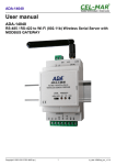
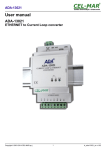
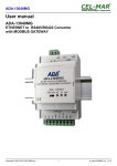
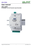
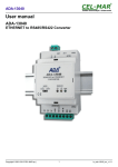
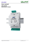
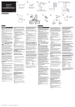
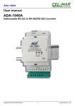
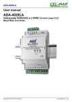
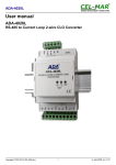
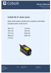
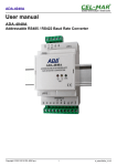
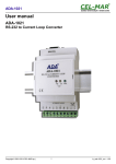
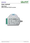
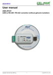
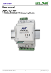
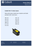
ADA-14110
User manual
ADA-14110
RS232 to Wi-Fi (802.11b) Wireless Serial Server with MODBUS
GATEWAY
Copyright © 2001-2014 CEL-MAR sp.j.
1
io_ada-14110_en v1.11
ADA-14110
Contents
1. GENERAL INFORMATION...................................................................................................................................................................... 4
1.1. WARRANTED INFORMATION ...................................................................................................................................................... 4
1.2. GENERAL CONDITIONS FOR SAFE USE.................................................................................................................................... 4
1.3. CE LABEL....................................................................................................................................................................................... 4
1.4. ENVIRONMENTAL PRESERVATION............................................................................................................................................. 4
1.5. SERVICE AND MAINTENANCE..................................................................................................................................................... 4
2. PRODUCT INFORMATION..................................................................................................................................................................... 4
2.1. PROPERTIES................................................................................................................................................................................. 4
2.2. DESCRIPTION................................................................................................................................................................................ 5
2.3. WIRELESS NETWORK COMMUNICATIONS (WLAN)..................................................................................................................6
2.3.1. COMMUNICATIONS IN THE TCP/UDP SOCKETS MODE...................................................................................................6
2.3.2. COMMUNICATIONS IN THE VIRTUAL SERIAL PORT MODE (RealPort)............................................................................6
2.3.3. COMMUNICATIONS IN THE SERIAL BRIDGE MODE ........................................................................................................6
2.3.4. COMMUNICATIONS IN THE INDUSTRIAL AUTOMATION MODE (Modbus Gateway)........................................................6
2.3.5. OTHER COMMUNICATION TYPES....................................................................................................................................... 6
2.4. ISOLATION..................................................................................................................................................................................... 6
3. INSTALLATION........................................................................................................................................................................................ 6
3.1. ASSEMBLING................................................................................................................................................................................. 7
3.2. CONNECTION TO WI-FI WIRELESS NETWORK (WLAN)...........................................................................................................7
3.2.1. CONNECTION OF THE WIRELESS SERIAL SERVER TO COMPUTER BY THE USE OF WIRELESS NETWORK
ADAPTER......................................................................................................................................................................................... 7
3.2.2. CONNECTION TO COMPUTER VIA NETWORK DEVICES ACCESS-POINT TYPE, ROUTER WI-FI................................7
3.2.3. CONNECTION TO COMPUTER VIA INTERNET BY THE USE ROUTER WI-FI / DSL........................................................8
3.2.4. CONNECTION FOR FUNCTIONING IN MODE TCP/UDP SERIAL BRIDGE ......................................................................9
3.2.5. CONNECTION OF THE WIRELESS SERIAL SERVER TO FUNCTIONING IN MODBUS GATEWAY MODE...................10
3.3. CONNECTING OF RS232 INTERFACE DEVICES...................................................................................................................... 11
3.3.1. CONNECTING OF DEVICE WITH RS232 POR, DTE TYPE (PC COMPUTER).................................................................11
3.3.2. CONNECTING OF DEVICE WITH RS232 POR,T DCE TYPE (MODEM, CODE READER)...............................................11
3.4. CONNECTING POWER SUPPLY................................................................................................................................................. 11
4. STARTUP............................................................................................................................................................................................... 12
5. CONFIGURATION................................................................................................................................................................................. 12
5.1. INITIAL CONFIGURATION USING ADAFINDER SOFTWARE....................................................................................................12
5.1.1. ADAFINDER INSTALLATION............................................................................................................................................... 12
5.1.2. NETWORK SETTING.......................................................................................................................................................... 12
5.2. CONFIGURATION AND MANAGEMENT BY THE USE OF INTERNET BROWSER...................................................................14
5.2.1. NETWORK CONFIGURATION............................................................................................................................................ 14
5.2.1.1. IP ADDRESS CONFIGURATION ............................................................................................................................... 14
5.2.1.2. WLAN CONFIGURATION........................................................................................................................................... 15
5.2.1.3. WLAN SECURITY SETTINGS.................................................................................................................................... 15
5.2.1.4. CONFIGURATION SETTINGS FOR WLAN NETWORK ACCESS AUTHORIZATION...............................................16
5.2.1.5. NETWORK SERVICES SETTINGS............................................................................................................................ 16
5.2.1.6. IP FORWARDING SETTINGS..................................................................................................................................... 16
5.2.1.7. SOCKET TUNNEL SETTINGS.................................................................................................................................... 16
5.2.1.8. ADVANCED NETWORK SETTINGS........................................................................................................................... 16
5.2.2. SERIAL PORT CONFIGURATION....................................................................................................................................... 16
5.2.2.1. PORT PROFILES (OPERATING MODES).................................................................................................................. 16
5.2.2.1.1. REALPORT (VIRTUAL PORT ) CONFIGURATION............................................................................................17
5.2.2.1.2. TCP SOCKETS CONFIGURATION.................................................................................................................... 17
5.2.2.1.2.1. TCP SERVER AND CLIENT CONFIGURATION........................................................................................18
5.2.2.1.2.2. THE 'ENABLE TCP KEEP-ALIVE' OPTION CONFIGURATION................................................................19
5.2.2.1.2.3. SERIAL PORT TRANSMISSION PARAMETERS CONFIGURATION........................................................19
5.2.2.1.3. UDP SOCKETS CONFIGURATION.................................................................................................................... 19
5.2.2.1.3.1. UDP CLIENT & SERVER CONFIGURATION IN CASE OF MASTER DEVICE.........................................19
5.2.2.1.3.2. UDP CLIENT & SERVER CONFIGURATION IN CASE OF SLAVE DEVICE...........................................20
5.2.2.1.3.3. SERIAL PORT TRANSMISSION PARAMETERS......................................................................................21
5.2.2.1.4. SERIAL BRIDGE PROFILE CONFIGURATION.................................................................................................21
5.2.2.1.4.1. SERIAL PORT TRANSMISSION PARAMETERS......................................................................................22
5.2.2.1.5. INDUSTRIAL AUTOMATION (MODBUS GATEWAY) CONFIGURATION..........................................................22
5.2.2.1.5.1. CONFIGURATION FOR COMMUNICATION WITH DEVICES MODBUS-MASTER TYPE.......................22
5.2.2.1.5.2. CONFIGURATION FOR COMMUNICATION WITH MODBUS-SLAVE TYPE DEVICE.............................24
5.2.2.1.5.3. SERIAL PORT TRANSMISSION PARAMETERS......................................................................................26
5.2.3. SYSTEM SETTINGS............................................................................................................................................................ 26
5.2.4. USERS CONFIGURATION.................................................................................................................................................. 26
5.2.4.1. CHANGING USER MANE AND PASSWORD ............................................................................................................26
5.2.4.2. ADDING NEW USER WITH LIMITED PERMISSIONS FOR CONFIGURATION OR MANAGEMENT ......................26
5.2.5. MANAGMENT...................................................................................................................................................................... 27
5.2.5.1. SERIAL PORTS MANAGEMENT................................................................................................................................ 27
5.2.5.2. CONNECTIONS MANAGMENT.................................................................................................................................. 27
2
ADA-14110
5.2.6. ADMINISTRATION............................................................................................................................................................... 27
5.2.6.1. FILE MANAGEMENT................................................................................................................................................... 27
5.2.6.2. BACKUP & RESTORE CONFIGURATION .................................................................................................................27
5.2.6.3. FIRMWARE UPDATE.................................................................................................................................................. 27
5.2.6.4. FACTORY DEFAULT SETTINGS................................................................................................................................ 27
5.2.6.5. SYSTEM INFORMATION............................................................................................................................................ 27
5.2.6.6. REBOOT...................................................................................................................................................................... 27
5.2.6.7. LOGOUT – ENDING MANAGEMENT AND CONFIGURATION..................................................................................27
6. USING VIRTUAL PORT SERVICE [REALPORT] ................................................................................................................................. 27
6.1. VIRTUAL PORT DRIVER INSTALLATION IN WINDOWS XP.....................................................................................................27
6.2. REALPORT CONFIGURATION IN WINDOWS XP...................................................................................................................... 28
7. FACTORY DEFAULT............................................................................................................................................................................. 30
8. PROBLEMS........................................................................................................................................................................................... 30
9. VERSIONS............................................................................................................................................................................................ 31
10. SPECIFICATION.................................................................................................................................................................................. 31
3
ADA-14110
1. GENERAL INFORMATION
Thank you for your purchase of CEL-MAR Company product. This product has been completely tested and is covered by a two year
warranty on parts and operation from date of sale.
If any questions or problems arise during installation or use of this product, please do not hesitate to contact Technical Support at +48
41 362-12-46 or e-mail [email protected].
1.1. WARRANTED INFORMATION
The ADA-14110 Serial Server is covered by a two year warranty from date of sale. In case of being damaged it will be repair or the
damaged component will be replace. The warranty does not cover damage caused from improper use, materials consumption or any
unauthorized changes. If the product does not function (is damaged), or not operate in accordance with the instructions, will be
repaired or replaced.
All warranty and no warranty repairs must be returned with paid transport and insuring to the CEL-MAR Company.
CEL-MAR Company under no circumstances won't be responsible for ensuing damage from improper using the product or as a result
of random causes: the lightning discharge, the flood, the fire and the like.
CEL-MAR Company is not be held responsible for damages and loss including: loss of profits, loss of data, pecuniary losses ensuing
from using or the impossibility of using this product.
In specific cases CEL-MAR Company discontinue all warranties and in particular do not follow the user manual and do not accept
terms of warranty by the user.
1.2. GENERAL CONDITIONS FOR SAFE USE
The device should be installed in a safe and stable places (eg, electroinstallation cabinet), the powering cable should be arranged so
as not to be exposed to trampling, attaching, or pulling out of the circuit.
Do not put device on the wet surface.
Do not connect devices for nondescript powering sources,
Do not damage or crush powering wires.
Do not make connection with wet hands.
Do not adapt, open or make holes in casings of the device!
Do not immerse device in water or no other liquid.
Do not put the fire opened on device sources: candles, an oil lamps and the like.
Complete disable from the supply network is only after disconnecting the power supply circuit voltage.
Do not carry out the assembly or dis-assembly of the device if it is enabled. This may result to short circuit and damage the device.
1.3. CE LABEL
CE symbol on organizing the company CEL-MAR a conformity of the device to the directive of the electromagnetic EMC
2004/108/WE compatibility means (Electromagnetic Compatibility Directive). The declaration of the agreement is
accessible through the contact with the technical service at the address e-mail: [email protected] or on the phone at the
+48 41 362-12-46.
1.4. ENVIRONMENTAL PRESERVATION
This sign on the device inform about putting expended device with other waste materials. Device should send to the
recycling. (In accordance with the act about the Electronic Appliance Expended from day 29 of July 2005)
1.5. SERVICE AND MAINTENANCE
The ADA-14110 does not require the servicing and maintenance.
Technical support is available at number +48 41 362-12-46 in 8.00-16.00, from Monday to Friday.
2. PRODUCT INFORMATION
The Server is delivered with: User Manual, antenna and ADANet software CD.
Attention!
Class A device designed for installation in environments commercial and light industrial. In residential environment may cause harmful
interference radio-electric, in which case the user will have to to take appropriate steps to eliminate them.
2.1. PROPERTIES
●
●
●
●
●
●
●
●
●
●
●
●
●
●
●
●
Operating with the data rates up to 11Mbps on the 2,4GHz frequency in the wireless network (IEEE 802.11b standard),
Baud rate in wireless network 1, 2, 5.5, 11 Mbps,
Modulation CCK(11/5 Mbps), DQPSK(2 Mbps), DBPSK(1Mbps),
Sensitivity of receiver: -82dBm for 11Mbps, -87dBm for 5.5Mbps, -89dBm for 2Mbps, -92dBm for 1Mbps,
Channels number: 11 (USA/Canada), 13 (Europe), 14 (Japan),
Antenna connection via SMA connector,
Wireless network security: WEP (64/128-bit encryption), WPA (128-bit encryption), WPA2 (128-bit encryption), PEAP, PSK (preshared key mode),
Protocols: TCP, UDP, DHCP, SNMP, SSL/TLS, Telnet, Rlogin, LPD, HTTP/HTTPS, SMTP, ICMP, IGMP, ARP,
WWW sever implemented for configuration of the server ports,
Configuration of net service
Configuration of net services according to user personal setting,
Static or dynamic IP address (added by DHCP server),
Diagnostics of serial and network port,
Encoded transmission: SSL v3.0/TLS v1.0 - DES (56-bit), 3DES (168-bit), AES (128/256-bit),
Operating in modes: virtual serial port, serial bridge TCP, serial bridge UDP, TCP or UDP socket, MODBUS Data Gateway,
Transmitted RS232 signals: a) for version without interface isolation: Rx, Tx, RTS, CTS, DTR, DSR, DCD, b) for version with
4
ADA-14110
interface isolation: Rx, Tx, RTS,
● Baud rate of RS232 (bps): 50, 75, 110, 134, 150, 200, 300, 600, 1200, 1800, 2400, 4800, 9600, 14400, 19200, 28800, 38400,
57600, 115200, 230400,
● RS232 data format: number of data bits: 5, 6, 7, 8; Parity control: None, Odd, Even, Constantly 1, Constantly 0; Stop Bits: 1, 2,
● Transparent for all protocols which data format is compatible with above specification of RS232 interface eg. MODBUS, DNP,
PROFIBUS and other,
● Implemented protocol converter MODBUS-TCP to MODBUS-RTU/ASCII (MODBUS Data Gateway),
● Operating in the mode MODBUS-RTU Master/Slave and MODBUS-ASCII Master/Slave,
● Connection of the RS-232 interface via DSUB-9M (male) connector,
● Stable external power supply 10 - 30 VDC,
● Up to 4W power consumption,
● ~3kV= optoisolation between interfaces RS232 and Wi-Fi (version 2-way isolation),
● 1kV= or 3kV= galvanic isolation between RS232 interface and power supply (version 2-way isolation),
● 1000V= or 3000V= galvanic isolation between RS232 interfaces and power supply,
● Protection against power supply reverse connection,
● DIN 43880 standard - mounting in typical electro-installation unit,
● Rail mounting according to DIN35 / TS35 standard,
● Dimensions (W x D x H) 53mm x 58mm x 90mm,
● Antenna dimensions: length 110mm, diameter 9mm.
2.2. DESCRIPTION
RS-232 to Wi-Fi
WIRELESS SERIAL SERVER
RS-232
DCD DSR DTR CTS RTS
RX
ACT
RS-232 to Wi-Fi
WIRELESS SERIAL SERVER
RS-232
TX PWR
7 mm
LINK
(Wi-Fi)
ADA-14110
90mm
ADA-14110
RST
RTS
RX
ACT
Network activity
transmitting / receiving
90mm
LINK
(Wi-Fi)
Vss-
ACT
Vss+
RST
10mm
Vss-
Vss+
10mm
112,50 mm
112,50 mm
The ADA-14110 wireless serial server transmits data between devices equipped with the RS232 interface via the wireless network
WLAN. The data transmission is without the interference into the format of transmitted data. The operating in the Wi-Fi WLAN wireless
network can be in the virtual serial port mode (port server), MODBUS Data Gateway, TCP and UDP serial bridge, TCP and UDP
socked. The MODBUS Data Gateway converts protocols MODBUS-RTU master/slave and MODBUS-ASCII master/slave to MODBUSTCP protocol and reverse. It lets to integrate devices MODBUS-RTU/ASCII with MODBUS-TCP devices in one network. ADA-14110
supports protocols such as: TCP, UDP, DHCP, SNMP, SSL/TLS, Telnet, Rlogin, LPD, HTTP/HTTPS, SMTP, ICMP, IGMP, ARP. The
server has WWW server for remote configuration and management by the use of internet browser and has the baud rate up to
230,4kbps.
This device has standard DB-9M (male) connector for RS232 interface, screw terminal block for connection of power supply and SMA
for aerial Wi-Fi network. ADA-14110 use signals as follow: Rx, Tx, RTS, CTS, DTR, DSR, DCD of RS232 interface and to this interface
can be connected telephone switchboards, barcode scanners, modems, scales, magnetic card readers, etc.
It is adapted to supply an external voltage source in scope from 10V= to 30V= and 4W power. The server has protection against
power supply reverse connection and ESD 15kV short-circuit protection and surge on RS232 interface lines.
The range of transmission in the wireless network Wi-Fi (IEEE 802.11b) :
- in buildings from 30m to 150m,
- in open area to 300m,
The transmission range can be increased after the application of additional directional antennas.
ADA-14110 is sold with drivers, which after installation, create in operating system additional COM port on the next free number e.g.
COM3. It can be use as standard COM port but it isn't hardware port but virtual, create in Windows system. This is the reason why
some applications running in DOS and use this port, can operate improperly.
LINK
Connection activity
TX PWR
-
SMA connector
of Wi-Fi interface
(RS-232)
10mm
10mm
(RS-232)
53mm
Version without RS232 interface
isolation
+
58mm
53mm
Version with RS232 interface
isolation
Fig. 1. ADA-14110 view
Fig. 2.View of Wi-Fi and power connectors
5
ADA-14110
2.3. WIRELESS NETWORK COMMUNICATIONS (WLAN)
2.3.1. COMMUNICATIONS IN THE TCP/UDP SOCKETS MODE
Communication in the mode TCP/UDP sockets allows an application (SCADA, MMI) to transfer data to the serial port of ADA-14110
via Wi-Fi network, by the use client and server TCP/UDP services.
2.3.2. COMMUNICATIONS IN THE VIRTUAL SERIAL PORT MODE (RealPort)
Communication in the virtual serial port mode allows an application (SCADA, MMI) to transfer data to the serial port of ADA-14110 via
Wi-Fi network, by the use virtual COM port, created in an operating system.
2.3.3. COMMUNICATIONS IN THE SERIAL BRIDGE MODE
Communication in the serial bridge mode allows to transfer data via Wi-Fi network between serial ports of the servers port in one-toone topology or one-to-many by the use client and server TCP/UDP services.
2.3.4. COMMUNICATIONS IN THE INDUSTRIAL AUTOMATION MODE (Modbus Gateway)
Communication in the MODBUS Gateway (IA) mode allows to convert MODBUS-RTU master/slave protocol and MODBUS-ASCII
master/slave protocol to MODBUS-TCP protocol and inversely. It's let to integrate MODBUS-RTU/ASCII devices with MODBUS-TCP
devices in a single network.
2.3.5. OTHER COMMUNICATION TYPES
The ADA-14110 port server can be configured in other communication types, like:
– terminal mode,
– modem emulation mode,
– console mode,
– user mode.
2.4. ISOLATION
The ADA-14110 has not the galvanic isolation or has 2-way, 1kV= or 3kV= galvanic isolation (depend on version, described in section
VERSIONS).
WITHOUT ISOLATION
R232
2-WAY ISOLATION
Wi-Fi
R232
Power Supply
10 - 30VDC
Wi-Fi
Power Supply
10 - 30VDC
Fig. 3. Isolation diagram
3. INSTALLATION
This chapter will show how to connect the ADA-14110 to RS232 bus, Wi-Fi wireless network (WLAN) and power supply and how to
use it.
To reduce disturbance from environment, it is recommended to:
– use multipair type shielded cables, which shield can be connected to the earthing on one end of the cable,
– use the suitable diameter cable for power supply on account of voltage drop,
– use the powering cable with a suitable section because of the voltage drops,
– use the interference eliminators for powering the converter,
– lay signal cables at a distance of not less than 25 cm away from power cables,
– not powering the converters form the power-circuit of devices generate large impulse disturbance like contactors, relays, inverters.
6
ADA-14110
3.1. ASSEMBLING
The ADA-14110 case is adapted to assembly on TS-35 (DIN35) rail. To install converter should mount device on the rail upper part of
the case then press bottom part to to hearing characteristic „Click” sound.
Attention!!
Do not install Wi-Fi devices at a distance of less than 20cm from each other.
3.2. CONNECTION TO WI-FI WIRELESS NETWORK (WLAN)
Connection of the ADA-14110 to WI-FI wireless network (WLAN) can be done by the use of a devices like ACCESS-POINT, ROUTER
Wi-Fi or directly to computer, equipped with Wi-Fi card or other ADA-14110 port server.
In the connector of Wi-Fi interface of the serial server are two diodes (fig.2):
– ACT green, signalling the state of data transferring or receiving,
– LINK orange, signalling the active network connection.
Wireless Serial Server ADA-14110 can be use like :
– virtual serial port [RealPort],
– TCP serial bridge,
– UDP serial bridge,
The factory default settings of the ADA-14110 is:
– to connect to any free wireless network Wi-Fi. Therefore should be set the lowest, free channel of wireless transmission in the
setting of devices like ACCESS-POINT, ROUTER Wi-Fi, Wi-Fi card.
– to downloading the IP address from DHCP server. Therefore if there is not the DHCP server, to change IP address should be used
ADAFinder software (see p.5.1).
Details of the connection to wireless network will be described in the bellow chapters.
3.2.1. CONNECTION OF THE WIRELESS SERIAL SERVER TO COMPUTER BY THE USE OF
WIRELESS NETWORK ADAPTER
If there is not Access-POINT or Wi-Fi Router, the ADA-14110 can be connected directly to computer by the use of wireless network
adapter as on the figure below. Recommended network adapters USB to Wi-Fi:
– PENTAGRAM HORNET P6132-30,
– PENTAGRAM HORNET P6132-08,
– or other, operating in mode: Client Wi-Fi or Access Point (AP).
For configuration of the ADA-14110 wireless serial server, set wireless network adapter in the Access Point mode and make the
configuration as below:
– SSID adapter name: no name,
– channel: 1,
– authentication: non,
– encryption: non.
Power the ADA-14110 and when will connect to wireless network adapter run the ADAFinder software and make the initial
configuration according to pt. 5.1. INITIAL CONFIGURATION USING ADAFINDER SOFTWARE.
Wi-Fi (802.11b/g) connection,
„Ad-Hoc” type
PC with Wi-Fi adapter
ADA-14110
Fig. 4. Connection AD-HOC type between ADA-14110 and PC
3.2.2. CONNECTION TO COMPUTER VIA NETWORK DEVICES ACCESS-POINT TYPE, ROUTER
WI-FI
Figure below shows correct connection of the ADA-14110 to wireless network WLAN\LAN, by the use ACCESS-POINT, ROUTER WiFi. This type of connection allows the Wireless Serial Server functioning with PC in virtual serial port mode (RealPort) or TCP/UDP
sockets.
7
ADA-14110
LAN ETHERNET
ROUTER Wi-Fi or
ACCESS POINT / ETHERNET
Wi-Fi (802.11b/g) LAN
Device with
RS232
interface
ADA-14110
PC with Wi-Fi adapter
RS232
Fig. 5. Connection the ADA-14110 to WLAN/LAN network, functioning in virtual serial port mode or TCP/UDP sockets
3.2.3. CONNECTION TO COMPUTER VIA INTERNET BY THE USE ROUTER WI-FI / DSL
Figure below shows the correct connection of the ADA-14110 to PC via INTERNET, by the use wireless network with devices like
ROUTER Wi-Fi / DSL type. This type of connection allows the Wireless Serial Server functioning with PC in virtual serial port mode
(RealPort) or TCP/UDP sockets.
INTERNET
ROUTER Wi-Fi / DSL
Public IP address
ROUTER Wi-Fi / DSL
Public IP address
Device with
RS232 interface
ADA-14110
PC with Wi-Fi adapter
RS232
Location - A
Location - B
Fig. 6. Connection to functioning in virtual serial port mode (RealPort) or TCP/UDP sockets via INTERNET
8
ADA-14110
3.2.4. CONNECTION FOR FUNCTIONING IN MODE TCP/UDP SERIAL BRIDGE
Figures below show correct connection of ADA-14110 to wireless network and INTERNET network to functioning in TCP serial bridge
mode or UDP.
Wi-Fi (802.11b/g) Network, the connection „Ad-Hoc” type between
ADA-14110 Serial Servers.
Functioning in the mode of serial bridge TCP / UDP
Device with
RS232 interface
Device with
RS232 interface
ADA-14110
ADA-14110
RS232
RS232
Fig. 7. Connection to functioning in TCP/UDP serial bridge mode, one-to-one in LAN network
Wi-Fi (802.11b/g) Network, the connection „Ad-Hoc” type between
ADA-14110 Serial Servers.
Functioning in the mode of serial bridge UDP
SLAVE Device
with RS232
interface
ADA-14110
Static IP address
RS232
SLAVE Device
with RS232
interface
RS232
Urządzenie
z interfejsem
RS232
MASTER Device
with RS232
interface
RS232
Fig. 8. Connection to functioning in UDP serial bridge mode, one-to-many in WLAN network
9
ADA-14110
INTERNET
ROUTER Wi-Fi / DSL
Public IP address
ROUTER Wi-Fi / DSL
Public IP address
Device with
RS232
interface
ADA-14110
Device with
RS232
interface
ADA-14110
RS232
LOCATION - A
RS232
LOCATION - B
Fig. 9. Connection to functioning in TCP or UDP serial bridge mode via INTERNET network
3.2.5. CONNECTION OF THE WIRELESS SERIAL SERVER TO FUNCTIONING IN MODBUS
GATEWAY MODE
Figure below shows the correct connection of the ADA-14110 to wireless network Wi-Fi (WLAN) to operating in Industrial
Automation Mode (MODBUS Gateway). This type of connection allows to integrate the MODBUS-TCP devices and the MODBUSRTU/ASCII devices in one network.
MODBUS-TCP
PLC
MASTER
LAN ETHERNET
M
OD
BU
STC
BU S
ADA-14110
MODBUS Gateway
P
RS232
MODBUS-RTU/ASCII
-TC
P
LAN \ WLAN
Created on the ROUTER
MODBUS-TCP
MO
D
BU
S-T
C
-TCP
BUS
MOD
P
TC
SU
DB
MO
P
MO
D
ROUTER Wi-Fi / ETHERNET
ADA-14040
MODBUS Gateway
RS485 Bus
MODBUS-RTU/ASCII
PC with the SCADA / HMI
software
Fig. 10. Integration MODBUS-TCP with MODBUS-RTU/ASCII in one network by the use ADA-14110 with MODBUS Gateway
10
ADA-14110
3.3. CONNECTING OF RS232 INTERFACE DEVICES
3.3.1. CONNECTING OF DEVICE WITH RS232 POR, DTE TYPE (PC COMPUTER)
The ADA-14110 can be connected to RS232 port of PC computer by the use of the crossover cable CAB-DB9F/DB9F-C-1,8m
(available in our offer). Figure below shows the example connecting of the Wireless Serial Server to RS232 PC port.
Device with RS232
DTE type
ADA-14110
SMA connector
Wi-Fi
Wi-Fi
V-
RS232
DTE/DB-9M
Socked
DB-9F
Socked
DB-9F
RS232
DTE/DB-9M
DCD -1
1
1
DCD -1
Rx -2
2
2
Rx -2
Tx -3
3
3
Tx -3
DTR -4
4
4
DTR -4
DSR -6
6
6
DSR -6
GND -5
5
5
GND -5
RTS -7
7
7
RTS -7
CTS -8
8
8
CTS -8
RI -9 (NC)
9
9
RI -9
V+
Power
Vss+
Vss-
Fig. 11. The example connecting of the ADA-14110 to RS232 PC port
3.3.2. CONNECTING OF DEVICE WITH RS232 POR,T DCE TYPE (MODEM, CODE READER)
The ADA-14110 can be connected to the RS232 device DCE port type, by the use of of RS232 cable CAB-DB9F/DB9M-S-1,8m
(available in our offer). Figure below shows the example connecting.
Device with RS232
DCE type
ADA-14110
SMA connector
Wi-Fi
Wi-Fi
V-
RS232
DTE/DB-9M
Socked
DB-9F
Socked
DB-9M
RS232
DCE/DB-9F
DCD -1
1
1
DCD -1
Rx -2
2
2
Tx -2
Tx -3
3
3
Rx -3
DSR -4
DTR -4
4
4
DSR -6
6
6
DTR -6
GND -5
5
5
GND -5
RTS -7
7
7
CTS -7
CTS -8
8
8
RTS -8
RI -9 (NC)
9
9
RI -9
V+
Power
Vss+
Vss-
Fig. 12. The example connecting of a device with RS232 port DCE type (e.g. modem, barcode reader)
3.4. CONNECTING POWER SUPPLY
The power supply to the ADA-14110 should be DC (regulated) from the scope 10 V= to 30V= and nominal power more then 4W
(available in our offer). The power cable from DC power supplies to the device must not be longer than 3m. Observe the polarity,
connect positive (+) of DC power supplies to Vss+ and negative (-) end to Vss- terminal. The ADA-14110 has the protection from
opposite connection power supply.
11
ADA-14110
4. STARTUP
If connection was made properly the green LED PWR on front panel of converter should lit, if not check polarization of connected
power. When data is transmitted LEDs on Wi-Fi interface and RX, TX should blink. Those LED are described below:
LED
Description
Power
Signalization of the Power Supply
PWR
RS232 interface
RX
Signalling of data receiving from RS232 port
TX
Signalling of data transmitting from through RS232 port
RTS
ADA-14110 reports to device readiness data collection
CTS
Device confirms reception RTS signal from ADA-14110. (version without isolation)
DTR
Readiness of ADA-14110 to receive/send data (version without isolation)
DSR
Readiness of Device to receive/send data (version without isolation)
DCD
Level of the signal received (version without isolation)
Wi-Fi wireless interface
Yellow
Lights continuously – indicates the connection between ADA-14110 and the Access Point.
Flashing of low frequency - indicates work in "ad hoc" mode.
Flashing at a high frequency - network searching.
Green
Signalling data transmission
5. CONFIGURATION
The ADA-14110 Wireless Serial Server like most of network devices should be configured for proper functioning, it's needed
configuration of network services and network setting.
Below are described the stages of software installation and network setting configuration of converter.
5.1. INITIAL CONFIGURATION USING ADAFINDER SOFTWARE
5.1.1. ADAFINDER INSTALLATION
The initial configuration of wireless Wi-Fi (WLAN) network setting at the ADA-14110 can be made by using ADAFinder or ADAWiz
software. The installation is automatically after insert the CD (compact disc) to an optical drive. If the autorun doesn't start, should run
the file setup.exe located in main CD catalogue. After installation the software ADAFinder and ADAWiz are available in Start>Programs->CEL-MAR->ADANet.
Before running ADA Finder software should be set the option [Obtain an IP address automatically] in TCP/IP protocol configuration
of Wi-Fi network adapter - it let find the Wireless Serial Server in WLAN network. Run ADAFinder software.
5.1.2. NETWORK SETTING
The ADAFinder is use for configuration of the Serial Server's network setting.
Before running the ADAFinder should be disabled the System FireWall!
After running, the program is searching local network (LAN , WLAN) and if find the ADA-14110, will add them to the list of available
port servers [Devices:] Fig.13.
To change the network setting of ADA-14110, should:
– select the converter from the list [Devices:] and press [Configure IP Settings],
– in windows [Set IP Address] select option 'Automatically obtain network settings via DHCP' (default setting) or 'Manually
configure network setting'. In case of manual configuration should be enter IP Address of the converter, Subnet Mask, Default
Gateway and the Password (default: dbps) of the ADA-14110 administrator for authorization of changes.
– press [Apply], the configuration will be saved to the serial server and will restart. After message 'Operation made successfully',
press [Refresh List] in ADAFinder window. After re-searching the lists of available port servers [Devices:] will be refreshed.
Other buttons of the program main menu:
– selecting the serial server from the list and pressing [Reboot Device], will make programmable reset – new configuration of
network setting will be activated,
– selecting the serial server from the list and pressing [Device Information], will show a window information about the settings,
– selecting the serial server from the list and pressing [Open Web Interface], will run Internet browser and open the configuration
page of the serial server.
12
ADA-14110
Fig. 13. The initial configuration by ADAFinder software
Fig. 14. ADAFinder configuration of IP network address
13
ADA-14110
5.2. CONFIGURATION AND MANAGEMENT BY THE USE OF INTERNET BROWSER
Integrated WWW server to the ADA-14110 enable to easy configuration and diagnostics of LAN and WAN network devices by the use
Internet browser.
For configuration open the Internet Browser and type the address http://<converter-ip-address>/admin/administration.htm. The
login windows will open. Enter User name and Password as follow:
Username: root
Password: dbps
If the the Username and the Password are correct will open the page as below.
Fig. 15. The web page for configuration and management of the ADA-14110
5.2.1. NETWORK CONFIGURATION
5.2.1.1. IP ADDRESS CONFIGURATION
To make a changes of default setting or new configuration of the ADA-14110, select on left panel Configuration -> Network and then
on right [ WiFi IP Settings] (Fig.16) and make the selection: Obtain an IP address automatically using DHCP or Use the following
IP address (in this option, enter IP Address of the serial server, Subnet Mask, Default Gateway), press [Apply] for save. After the
message Changes have been saved successfully, from left menu select Administrator -> Reboot on right press [Reboot], will be
programmable reset of the serial server and new configuration of network setting will be activated.
14
ADA-14110
Fig. 16. The web page for network setting of the ADA-14110
5.2.1.2. WLAN CONFIGURATION
To make a changes of default setting or new configuration of the ADA-14110, select on left panel Configuration -> Network and then
on right [WiFi LAN Settings].
Enter in [Network name] or [SSID] the name of the network, to which the serial server will be connected. If the [Network name] will
be empty, the ADA-14110 will connect to first, found wireless network.
The type of connection to wireless network can be configured by options like:
[• Connect to any available wireless network]
[• Connect to access point (infrastructure) networks only]
[• Connect to peer-to-peer (ad-hoc) networks only]
From the list [Country] select the country, this choice will reduce settings of channels to the list of legally defined for the country.
From the list [Channel] select the channel on which the server will operate. Selection the Auto-Scan from list will cause searching of
all available frequencies until the Server will not find available wireless networks Access Point type or Ad-Hoc to which can connect.
Selection [Enable Short Preamble] let enlarge capacity/ efficiency of wireless network - if the network supports the Short Preamble.
5.2.1.3. WLAN SECURITY SETTINGS
To make a changes of default setting or new configuration of ADA-14110, select on left panel Configuration -> Network and then on
right [WiFi Security Settings]. In this section can be configured security and access authorization to W-Fi network in many ways.
The serial server automatically will choose and specify the mode of authentication and encryption method at accessing to Wi-Fi
network.
If wireless network uses Open System structure, an unsecured, should not be switched the factory settings.
Attention !
The settings of WPA protection need wireless network based on devices Access Point type and are not available in networks
Ad-Hoc (peer-to-peer) type.
WPA-PSK protection is available only if is entered the name of network in [Network Name] or SSID.
Section [WiFi Security Settings] consists of:
• Network Authentication
• Data Encryption
• WEP Keys
• WPA PSK
• Username/Password
Attention !
For detailed information about configuration this section are available after logging on the port server.
15
ADA-14110
5.2.1.4. CONFIGURATION SETTINGS FOR WLAN NETWORK ACCESS AUTHORIZATION
To make a changes of default setting or new configuration of the ADA-14110, select on left panel Configuration -> Network and then
on right [WiFi 802.1x Authentication Settings]. These options are only configurable when [WEP with 802.1x authentication] or
[WPA with 802.1x authentication] are enabled on the [WiFi Security Settings] tab.
Attention !
For detailed information about configuration this section are available after logging on the port server.
5.2.1.5. NETWORK SERVICES SETTINGS
To make a changes of default setting or new configuration of the ADA-14110, select on left panel Configuration -> Network and then
on right [Network Services Settings]. This section is used to enable or disable many of network services or configuration of
TCP/UDP ports on which they operate.
Attention !
For detailed information about configuration this section are available after logging on the port server.
5.2.1.6. IP FORWARDING SETTINGS
To make a changes of default setting or new configuration of ADA-14110, select on left panel Configuration -> Network and then on
right [IP Forwarding Settings]. This section is used to manage of IP routing (forwarding) of packets between network interfaces.
Static routes may be configured and added to the IP routing table to provide additional packet routing rules.
Attention !
For detailed information about configuration this section are available after logging on the port server.
5.2.1.7. SOCKET TUNNEL SETTINGS
To make a changes of default setting or new configuration of ADA-14110, select on left panel Configuration -> Network and then on
right [Socket Tunnel Settings]. This section is used to connect two network devices - one the ADA-14110 Wireless Serial Server's
local network and the other on the remote network.
Attention !
For detailed information about configuration this section are available after logging on the port server.
5.2.1.8. ADVANCED NETWORK SETTINGS
To make a changes of default setting or new configuration of ADA-14040, select on left panel Configuration -> Network and then on
right [Advanced Network Settings]. This section is used to fine tune the network connection and network interfaces. The default
settings will typically work in most situations.
Attention !
For detailed information about configuration this section are available after logging on the port server.
5.2.2. SERIAL PORT CONFIGURATION
The configuration of serial port of the ADA-14110 server includes: port description, setting of port profile (operating mode) and setting
of serial transmission parameters (baud rate, data bits, parity, stop bits).
Select on left panel Configuration -> Serial Ports and then on right [Port 1], will open the configuration details page, includes:
- Port Profile Settings,
- Basic Serial Settings,
- Advanced Serial Settings,
5.2.2.1. PORT PROFILES (OPERATING MODES)
Select on right panel Serial Port Configuration -> Port Profile Settings and then press Change Profile... will open the page Select
Port Profile for selection of port profiles (fig. 17).
Attention !
For detailed information about configuration this section are available after logging on the port server.
16
ADA-14110
Fig. 17. The web page of selection the serial port profile
5.2.2.1.1. REALPORT (VIRTUAL PORT ) CONFIGURATION
Choosing RealPort (Virtual Port, Fig. 17) is configured the serial port of ADA-14110, for communication with virtual port COM of
computer. Press [Apply] for save. After installation driver (RealPort) of virtual port COM (see chapter 6) in operating system, data
sending by application to this port are transferred through WLAN/WAN to the ADA-14110 serial server and are present on his serial
port. The driver RealPort installation is presented in chapter 6. Normally RealPort service allows for one connection through
WLAN/LAN/WAN, between computer and server port.
Connection from other computers to the converter will be not taken, what will cause the error message.
5.2.2.1.2. TCP SOCKETS CONFIGURATION
Choosing TCP Sockets is configured the serial port of ADA-14110, for direct communication with PC by the use of TCP socked. Data
sending by application to TCP socked are transferred through WLAN/LAN/WAN to the ADA-14110 serial server and are present on his
serial port. To save selected configuration, press the button [Apply].
17
ADA-14110
5.2.2.1.2.1. TCP SERVER AND CLIENT CONFIGURATION
After saving the TCP Sockets profile, will open section TCP Server Settings (picture below), includes configuration of:
– port for Telnet service; standard 2001,
– port for serial port service; standard 2101 (through this port are transferred data to serial port of converter),
– port for security access to serial port service; standard 2601 (through this port are transferred data to serial port of converter),
and possibility of selection Enable TCP Keep Alive – connection will be kept, even if the data is not transmitted over the network.
Fig. 18. Example configuration of TCP server
For configuration of TCP Client Settings (Fig 19), select Automatically establish TCP connections, connection between client and
TCP server will be automatically. Then select Always connect and maintain connection option and in section Establish connection
to the following network service enter IP address of device to which TCP client will send data, select service and enter port. There
is also possible to select an option Enable TCP Keep-Alive – connection will be kept, even if the data is not transmitted over the
network.
For saving the configuration press [Apply].
Fig. 19. Example configuration of TCP client
ATTENTION !
Default port of serial port service is 2101.
If on the local network is conflict with other network service using the same port, in the serial server's port configuration
change number of port into another for the server and client service .
18
ADA-14110
5.2.2.1.2.2. THE 'ENABLE TCP KEEP-ALIVE' OPTION CONFIGURATION
Option Enable TCP Keep-Alive keeps connection between server and client, even if the data is not transmitted over the network and
reconnection in case of interruption.
Configuration of this option can be made by selection Configuration > Network > Advanced Network Settings > TCP Keep-Alive
Settings. In this section can be configured:
– Idle Time – specifies the period of time (scope 10 sec. - 24 hours) that a TCP connection has to be idle before a keep-alive is sent.
– Probe Interval – the time in seconds between each keep-alive probe (scope 10 – 75 sec.),
– Probe Count – the number of times TCP probes the connection to determine (scope 5 – 30 trials).
5.2.2.1.2.3. SERIAL PORT TRANSMISSION PARAMETERS CONFIGURATION
For proper operation of the ADA-14110 wireless serial server with device connected to his RS232 serial port, should be set the same
transmission parameters for both devices.
Select Basic Serial Settings and enter Baud Rate, Data Bits, Parity, Stop Bits, the same parameter like has device connected to
the serial port of the ADA-14110.
5.2.2.1.3. UDP SOCKETS CONFIGURATION
Choosing UDP Sockets is configured the serial port of the ADA-14110 for direct communication with PC or other device connected to
the network by the use of UDP socked. Data sending by application or other device/s to this port are transferred through
WLAN/LAN/WAN to the ADA-14110 and are present on his serial port. Press [Apply] for save the configuration
5.2.2.1.3.1. UDP CLIENT & SERVER CONFIGURATION IN CASE OF MASTER DEVICE
After saving the UDP Sockets profile, will open section UDP Server Settings with operating parameters like on picture below. Set an
access to UDP server on e.g. 2101 port. Then select Automatically send serial data in section UDP Client Settings, this
automatically send received data by the use UDP client service to the SLAVE device connected to LAN/WAN through e.g. ADA-13020,
ADA-13028L, ADA-13040MG, ADA-13110, ADA-14040, ADA-14110.
On the lists Send data to the following network services are addresses of network devices and ports to which will be send data. In
field:
– Description - enter e.g. location of the serial server and SLAVE device,
– Send To
- enter IP address of e.g. serial server, connected to SLAVE device,
– UDP Port
- enter the number of port on which is working UDP Server of the serial server connected to SLAVE device and press
[Add]
In the section Send data under any of the following conditions, is recommended to set parameters like on picture bellow.
For saving the configuration of UDP client and server for MASTER device, press [Apply].
19
ADA-14110
Fig. 20. Example configuration of the UDP server&client on serial server connected to MASTER device
5.2.2.1.3.2. UDP CLIENT & SERVER CONFIGURATION IN CASE OF SLAVE DEVICE
Set operating parameters of UDP server for SLAVE device connected via serial port to ADA-14110, eg like on picture below. Set an
access to UDP server on e.g. 2101 port. Then select Automatically send serial data in section UDP Client Settings, this
automatically send received data by the use UDP client service to the MASTER device connected to LAN / WAN through e.g.
ADA-13020, ADA-13028L, ADA-13040MG, ADA-13110, ADA-14040, ADA-14110.
On the lists Send data to the following network services are addresses of network devices and ports to which will be send data. In
field:
– Description - enter e.g. location of the serial server and MASTER device,
– Send To
- enter IP address of e.g. serial server , connected to MASTER device,
– UDP Port
- enter the number of port on which is working UDP Server of the serial server connected to MASTER device and
press [Add]
In the section Send data under any of the following conditions is recommended to set parameters like on picture bellow.
For saving the configuration of UDP client and server for SLAVE device, press [Apply].
20
ADA-14110
Fig. 21. Example configuration of the UDP server&client on serial server connected to SLAVE device
ATTENTION !
Default port of serial port service is 2101.
If on the local network is conflict with other network service using the same port, in the serial server's port configuration
change number of port into another for the server and client service .
5.2.2.1.3.3. SERIAL PORT TRANSMISSION PARAMETERS
For proper operation of the ADA-14110 wireless serial server with device connected to his RS232 serial port, should be set the same
transmission parameters for both devices.
Select Basic Serial Settings and enter Baud Rate, Data Bits, Parity, Stop Bits, the same parameter like has device connected to
the serial port of the wireless serial server.
5.2.2.1.4. SERIAL BRIDGE PROFILE CONFIGURATION
Choosing the Serial Bridge profile enable direct communication between two devices connected to two ADA-14110 wireless serial
servers over the network as if they were connected with a serial cable. A properly configured the ADA-14110 will start automatically
communication with each other. Press [Apply] for save the configuration
After saving the Serial Bridge profile, will open section Serial Bridge Settings (fig.22) with operating parameters like on picture below.
Select Initiate serial bridge to the following device option and enter IP address and 2101 Port of ADA-14110 with which to create
the serial bridge over the network. Additionally can be selected [Enable TCP Keep-Alive] option which keeps connection even if the
data is not transmitted. Select Allow other devices to initiate serial bridge and enter 2101 port on which other the wireless serial
servers will automatically start communication, and can be set also [Enable TCP Keep-Alive] option which keeps connection even if
the data is not transmitted.
21
ADA-14110
Fig. 22. Example configuration of TCP Serial Bridge
ATTENTION !
Default port of serial port service is 2101.
If on the local network is conflict with other network service using the same port, in the serial server's port configuration
change number of port into another for the server and client service.
5.2.2.1.4.1. SERIAL PORT TRANSMISSION PARAMETERS
For proper operation of the ADA-14110 wireless serial server with device connected to his RS232 serial port, should be set the same
transmission parameters for both devices.
Select Basic Serial Settings and enter Baud Rate, Data Bits, Parity, Stop Bits, the same parameter like has device connected to
the serial port of the wireless serial server.
5.2.2.1.5. INDUSTRIAL AUTOMATION (MODBUS GATEWAY) CONFIGURATION
Choosing the Industrial Automation (Modbus Gateway, Fig.17) profile, will be possible to configure the ADA-14110 wireless serial
servers's serial port for communication by the use of MODBUS-RTU master/slave or MODBUS-ASCII master/slave protocol. The
ADA-14110 converts frames of MODBUS-RTU/ASCII protocol to MODBUS-TCP and send via WLAN/LAN/WAN to devices with
MODBUS-TCP protocol or other servers (ADA-14040, ADA-14110, ADA-13040MG, ADA-13110MG) operating in Industrial
Automation (MODBUS Gateway) mode with connected MODBUS-RTU/ASCII devices. Press [Apply] for saving this profile.
5.2.2.1.5.1. CONFIGURATION FOR COMMUNICATION WITH DEVICES MODBUSMASTER TYPE
After saving the configuration, in the section Industrial Automation Settings, press [Change Protocol] link. Then in section Select
IA Protocol (figure below) select type of device, connected to serial port of ADA-14110, as Serial Master and MODBUS-RTU or
MODBUS-ASCII protocol for communication between connected devices. Press [Apply] for saving configuration.
Fig. 23. Example configuration for communication with MODBUS-MASTER devices – choice of devices and protocols
Set the options in section Modbus RTU Settings like on the figure below and press [Apply].
22
ADA-14110
Fig. 24. Example configuration for communication with MODBUS-MASTER devices – Modbus RTU setting
Then select section Slave Destinations (Packet Routing) – figure below.
In this section press [Add], enter the IP address of Slave type devices, to which Master will send requests and receive responses.
Fig. 25. Example configuration for communication with MODBUS-MASTER devices – table configuration of SLAVE type
devices
In section Destination Settings (fig. below) set the options of requests from Master device to Slave device, in fields:
– Host name - enter IP address of Slave device.
– Protocol
- set protocol which will be send to Slave device – in this case will be Modbus/TCP.
– Transport
- set TCP protocol .
– Network port - set port 502.
Press [Apply] for saving configuration. Then press again [Add] for adding another Slave device.
Then select section Slave Destinations (Packet Routing), when all Slave devices are added and set, press [Apply].
23
ADA-14110
Fig. 26. Example configuration for communication with MODBUS-MASTER devices – table entry configuration for SLAVE type
devices
On section Advanced Protocol Settings (fig. below), set the timeout by entry:
– Character timeout - value in ms., maximum delay or gap betweens bytes of a message – default 20 ms.
– Message timeout - value in ms., maximum delay or gap betweens bytes of a message – default 2500ms; this time must be less
than the timeout set on SLAVE and MASTER MODBUS-RTU devices.
For saving the Advanced Protocol Settings press [Apply].
Fig. 27. Example configuration for communication with MODBUS-MASTER devices – configuration of timeout parameters for
MASTER type device
5.2.2.1.5.2. CONFIGURATION FOR COMMUNICATION WITH MODBUS-SLAVE TYPE
DEVICE
After saving the configuration, in the section Industrial Automation Settings, press [Change Protocol] link. Then in section Select
IA Protocol (figure below) select type of device, connected to serial port of ADA-14110, as Serial Slave and MODBUS-RTU or
MODBUS-ASCII protocol for communication between connected devices. Press [Apply] for saving configuration.
24
ADA-14110
Fig. 28. Example configuration for communication with MODBUS-SLAVE devices – choice of devices and protocols
Set options in section [Modbus RTU Settings] eg. as on picture below. Press [Apply] for saving configuration.
Fig. 29. Example configuration for communication with MODBUS-SLAVE devices – Modbus RTU setting
Go to section Modbus/TCP Network Settings [Global], configuration options set as on the figure below. Press [Apply] for saving
configuration.
Fig. 30. Example configuration for communication with MODBUS-SLAVE devices
25
ADA-14110
ATTENTION !
Default port of Industrial Automation (Modbus Gateway) service is 502.
If on the local network is conflict with other network service using the same port, in the serial server's port configuration
change number of port into another for the server and client service.
On section Advanced Protocol Settings (fig. below), set the timeout by entry:
– Character timeout - value in ms., maximum delay or gap betweens bytes of a message – default 20 ms.
– Message timeout - value in ms., maximum delay or gap betweens bytes of a message – default 2500ms; this time must not be
less than the timeout set on MODBUS MASTER devices / SCADA/HMI software.
For saving the Advanced Protocol Settings press [Apply].
Fig. 31. Example configuration for communication with MODBUS-SLAVE devices – configuration of timeout parameters for
SLAVE type device
5.2.2.1.5.3. SERIAL PORT TRANSMISSION PARAMETERS
For proper operation of the ADA-14110 wireless serial server with device connected to his RS232 serial port, should be set the same
transmission parameters for both devices.
Select Basic Serial Settings and enter Baud Rate, Data Bits, Parity, Stop Bits, the same parameter like has device connected to
the serial port of the wireless serial server.
5.2.3. SYSTEM SETTINGS
Select on left panel menu Configuration -> System and then on right will be selections as follow:
– Device Identity Settings - allows to add name of the wireless serial server, describe the location and add identification number,
– Simple Network Managment Protocol Setings (SNMP) - allows to make the configuration of management protocol SNMP.
5.2.4. USERS CONFIGURATION
On the configuration page Users are two sections:
– Users - allows to configure the method of login to ADA-14110. Selecting the option Enable user logins means that after enter the
address http://<adres-ip-konwertera>/admin/administration.htm to internet browser, will open login window and will be necessary to
enter user name and password.
– Configure Users - allows to add additional user, change password, configure access and permissions for each defined users.
5.2.4.1. CHANGING USER MANE AND PASSWORD
Changing the default user root and password, can be done as follow :
1. press user mane root in section Users Configuration->Configure Users,
2. enter new user name and password.
3. press [Apply] for saving.
5.2.4.2. ADDING NEW USER WITH LIMITED PERMISSIONS FOR CONFIGURATION OR
MANAGEMENT
For adding new user with limited permissions for configuration or management follow the steps below:
1. From menu Configuration select Users,
2. In section Configure Users, press [New...],
3. Enter user mane (eg. admin) and password – twice, and press [Apply],
4. Will open the page Users Configuration, where in section Configure Users, will be new user name.
Now it is possible to configure access permissions to the wireless serial server, and permissions for configuration of this new user.
Configuration of access to the wireless serial server:
1. From menu Configuration select Users,
2. In section Configure Users, select added user eg. admin,
3. Will open the page User Configuration – admin, where are sections:
A/ User Configuration – possibility of rename user and password,
B/ User Access - method of access to the wireless serial server from the network:
Allow command line access – access using the Command Line Interface - telnet,
Allow web interface access – access using the internet browser.
C/ User Permissions - user permissions to configuration and management of the ADA-14110, where are an options:
None - no permission,
Read - permission to read,
Read Self - permission to read own settings, but not other users.
26
ADA-14110
Read/Write - full permission to read and write the setting.
Read/Write Self - permission to read and write own setting, but not other users.
Read All/Write Self - permission to read the setting for all users and modify only own setting (not other users).
Execute - permission to execute (start).
4. All changes are saved by pressing [Apply].
5.2.5. MANAGMENT
On left panel in menu Management are to sections :
– Serial Ports
– Connections
5.2.5.1. SERIAL PORTS MANAGEMENT
Section Serial Ports allows to identification connections/disconnections to the serial port of the ADA-14110 wireless serial server
through the network.
5.2.5.2. CONNECTIONS MANAGMENT
Section Connections allows to identification connections/disconnection to the ADA-14110 wireless serial server through the network.
5.2.6. ADMINISTRATION
The menu Administration allows :
– to delete/upload files with Java applet,
– to backup/restore configuration of converter,
– to update Firmware,
– to restore the factory default settings,
– to display system details information,
– to reboot the ADA-14110 wireless serial server.
5.2.6.1. FILE MANAGEMENT
Section File Management enables upload and delete Web and Java Applets provided by manufacturer. Uploaded index.htm or
index.html allows to automatically run the page in the web browser after entering http://address-ip-convertera/FS/WEB/index.htm
and login to the ADA-14110.
5.2.6.2. BACKUP & RESTORE CONFIGURATION
Section Backup/Restore enables backup to file or restore from file the user configuration of the wireless serial server.
5.2.6.3. FIRMWARE UPDATE
Section Update Firmware enables to make the update firmware form the file. Firstly should be done update the POST software before
updating the firmware – more details available on the web page http://www.cel-mar.pl.
5.2.6.4. FACTORY DEFAULT SETTINGS
The converter was configured by the manufacturer.
To restore factory default settings, select from menu Factory Default Settings. After that the converter will automatically reboot.
5.2.6.5. SYSTEM INFORMATION
Section System Information displays:
– General – device model , MAC address, firmware version, Boot version, POST version and more.
– GPIO – not applicable in the ADA-14110.
– Serial – port description, current settings of serial port, status of controlling lines and the statistics data transfer through the serial
port.
– Network – show statistics of Wi-Fi interface for IP, TCP, UDP, ICM protocols.
5.2.6.6. REBOOT
Section Reboot allows to make software reset of the ADA-14110. Pressing [Reboot] will start rebooting of server during 1 min.
5.2.6.7. LOGOUT – ENDING MANAGEMENT AND CONFIGURATION
After completion of the configuration or administration should be pressing Logout on left panel – logout from WWW server of ADA14110.
6. USING VIRTUAL PORT SERVICE [REALPORT]
6.1. VIRTUAL PORT DRIVER INSTALLATION IN WINDOWS XP
The installation of virtual serial port drivers should be done for the CD, by choosing:
– Win Server-2003-2008-2012
– Win-2000
– Win-98-ME
– Win-NT4.0SP5
– Win-Vista
– Win-XP-7-8
27
ADA-14110
Installation of Virtual serial port drivers is as follow:
1. connect the ADA-14110 to Wi-Fi (WLAN) and power supply (see p.3.),
2. press [Start] and select [Run...],
3. in the dialog window [Run] press [ Browse ],
4. select „My computer” and CD-Rom with „ADANET_DRV”,
5. select catalog Drivers/Windows/Win-XP-7-8,
6. select file „Setup.exe” for 32-bits system or „Setup64.exe” for 64-bits and press [Open],
7. when the installation window will appear press [Next],
8. will start the searching for the wireless serial servers in the network, founded devices will be added to the list.
9. select the wireless serial servers from the list for installation of virtual port driver and press [Next].
10. in window Describe the device select or not the Starting Com port and press [Finish]. The driver will be installed.
The Virtual Serial Port Drivers can be installed without connection of the ADA-14110 to Wi-Fi (WLAN) wireless network and it
is as follow:
1. press [Start] button, select [Run...]
2. in the dialog window [Run] press [ Browse ]
3. select „My computer” and CD-Rom with „ADANET_DRV”.
4. select catalog Drivers/Windows/Win-XP-7-8.
5. select file „Setup.exe” for 32-bits system or „Setup64.exe” for 64-bits and press [Open].
6. when the installation window will appear press [Next] .
7. will start the searching for converters in the network.
8. if no devices were not found press [Next].
9. should be set in the window Describe the device:
– IP address for wireless serial server,
– number of installing COM port (No. Ports)
– Starting COM
and press [Finish]. The driver will be installed.
In this way installed virtual port can require the configuration in case of connecting the wireless serial server to network.
6.2. REALPORT CONFIGURATION IN WINDOWS XP
After installation of RealPort drivers, can be done configuration by the use the Device Manager of Windows and it is as follow:
1. Press [ Start ], select [ Properties/Setting ], press [ Control Panel ].
2. Double click icon [ Administrative Tools] and [ Device Manager ]
3. Press [Ports (COM & LPT)]. On fig. 32 are shown available serial ports COM1, COM2 and COM7 marked as ADA-14110 which
was created after installation of RealPort driver.
4. Then select [Multi-port Serial Adapter], there will be the name ADA-14110 .
5. Double click the name and the window [Properties] will appear.
6. Select [Advanced] and press [Properties].
7. Enter new name of virtual port for wireless serial server. In the window [Advanced Properties] click [ADA-14110] and then
select [Properties], press [Rename Ports], now it is possible to change the name of virtual port driver for example COM5, COM11 etc.
To accept the changes press [OK].
8. Select IP address, MAC, DNS server for communication with virtual port driver. In the window [ Advanced Properties] click
[ADA-14110] and then select [Network] (Fig. 33), and set the IP address, MAC Address or DNS name of the wireless serial server
for communication with virtual port driver.
9. In the next window press [OK] to accept the changes.
28
ADA-14110
Fig. 32. Devices view on Windows XP
Fig. 33. Example configuration of multi-port serial adapter
29
ADA-14110
7. FACTORY DEFAULT
Parameter
Value
User name
root
Password
dbps
Wi-Fi Setting
IP address
Obtain an IP address automatically using DHCP
Network name (SSID)
No name
Type of connection to network
Connect to any available Wi-Fi network
Network Security
Open System
Profile port
RealPort/<unasigned>
Baud rate [bits/sec]
9600
Number of data bits
8
Parity Control
Non
Number of stop bits
1
Flow Control
Non
Serial Port
8. PROBLEMS
Problem
I forgot the password
Solution
Restoring Default Settings according to steps below:
1. Power OFF the ADA-14110,
2. Remove the cover of Wi-Fi connector,
3. Press RESET “RST” and holding the button turn the power ON,
4. Release the button after 20 sec. when the ADA-14110 will start with default settings.
Restoring Default Settings deletes existing configuration and the proper configuration should be
loaded to the converter form the backup.
I changed the configuration and
1. Enter in the Internet browser http://address-ip-server,
the wireless serial server isn't
2. Select the menu [Factory Default Settings] press [Restore].
functioning.
The Serial Server cannot be
found in the Network.
I. If IP address is not known or cannot be found by the use of ADAFinder software and yellow LED is
blinking with high frequency (signaling of network searching), restore Default Settings according to
steps below:
1. Power OFF the ADA-14110,
2. Remove the cover of Serial Server Wi-Fi connector,
3. Press RESET “RST” and holding the button turn the power on of ADA-14110,
4. Release the button and after 20 sec. the Serial Server will start with Default Settings (sec.7),
5. Wait about 1 min. and run ADAFinder for network searching.
II. If IP address is not known or cannot be found by the use of ADAFinder software and yellow LED
continuously lit (signaling establishing a connection between ADA-14110 and Access Point), follow
the steps below:
1.Power OFF the ADA-14110,
2. Set in the configuration of device like ACCESS-POINT, ROUTER Wi-Fi, Wi-Fi adapter, the lowest
free channel of wireless transmission – because ADA-14110 is connecting to any wireless network
during start.
3. Disable Firewall.
4. Turn the power on of ADA-14110.
5. Wait about 1 min. and run ADAFinder for network searching.
III. If IP address is not known or cannot be found by the use of ADAFinder software and yellow LED
is blinking with low frequency (signaling operation in 'ad-hoc' mode), follow the steps below:
1. Power OFF the ADA-14110,
2. Set in the configuration of device like ACCESS-POINT, ROUTER Wi-Fi, Wi-Fi adapter, the lowest
free channel of wireless transmission – because ADA-14110 is connecting to any wireless network
during start,
3. Disable Firewall.
4. Turn the power on of ADA-14110.
5. Wait about 1 min. and run ADAFinder for network searching.
30
ADA-14110
9. VERSIONS
ADA-14110 -
-
-
Electronic versions:
Basic
1
Galvanic isolation of RS232 interface:
No isolation – transmitted signals of
RS232: Tx, Rx, RTS, CTS, DTR, DSR,
DCD, GND .
1
Order example:
1kV DC – transmitted signals of RS232:
Tx, Rx, RTS, GND .
2
3kV DC – transmitted signals of RS232:
Tx, Rx, RTS, GND .
3
Product Symbol: ADA-14110-1-1-3
1 – basic version of electronic,
1 – non galvanic isolation,
3 – cover without inlets, plug-in screw terminal block,
Terminal & Terminal Cover:
Cover without inlets, screw terminal block
1
Cover without inlets, screw terminal block
2
Cover without inlets, plug-in screw terminal block
3
10. SPECIFICATION
Parameters
Connector
Max. number of connected device
Wi-Fi (802.11b)
RS232
SMA–plug + Antenna
DB-9M (Mail)
Depend on type of network addressing
1
11 Mbit/s
230,4 kbps
IEEE 802.3, IEEE 802.11b (2.4GHz)
EIA-232, CCITT V.24
Max. baud rate
Standards
Max. Line length
- inside building – from 30m to 150m,
- open area up to 300m,
- open area with use of additional antenna - up to
8000m.
Transmission line RS232
CAB-DB9F/DB9M-S-1,8m cable
Transmission type
Asynchronous full duplex, half duplex.
Optical Signalization
Up to 15 m
• PWR green LED – power supply,
• RX red LED - receive data on RS232 port,
• TX yellow LED - transmit data on RS232 port,
• RTS yellow LED – outgoing signal on RS232 port,
• CTS red LED - incoming signal on RS232 port, (version without isolation),
• CTS red LED - incoming signal on RS232 port, (version without isolation),
• DTR yellow LED – outgoing signal on RS232 port, (version without isolation),
• DSR red LED - incoming signal on RS232 port, (version without isolation),
• DCD red LED - incoming signal on RS232 port, (version without isolation),
Nominal Operating Conditions
10 - 24 – 30 V DC
Power requirements
Power Cable
Recommended length – up to 3m
4W
Power
Protection from reverse power polarization
Yes
Galvanic Isolation
1kVDC or 3kVDC 2-WAY depend on version
Optoisolation
~3kVDC between interfaces Wi-Fi and RS232
0 ÷ +23 ÷ +50°C
Operating temperature
Humidity
5 ÷ 95% - non-condensing
Location during work
Free
Mounting
Rail mounting according to DIN35 standard / TS35.
Electromagnetic compatibility
Resistance to disruptions : PN-EN 55024.
Emission of disruptions : PN-EN 55022, PN-EN 301 489-3 v1.4.1:2006, PN-EN 300
328 v1.7.1:2007.
31
ADA-14110
Safety requiring
According to the PN-EN60950.
Environment
Commercial and light industrial, A Class.
Casing
Dimensions
53 x 90 x 58mm,
Material
Noryl UL. 94 V-O
Degree of casing protection
IP40
Degree of terminal protection
IP20
0,10 kg
Weight
DIN EN50022, DIN EN43880
According to standards
Storing and Transportation
-40 ÷ +70°C
Storage temperature
5 ÷ 95% - non-condensing
Humidity
Dear Customer,
Thank you for purchasing CEL-MAR Company products.
We hope that this user manual helped connect and start up the ADA-14110 Wireless Serial Server. We also wish to inform you that
we are a manufacturer of the widest selections of data communications products in the world such as: data transmission converters
with interface RS232, RS485, RS422, USB, Current Loop, Fibre-Optic Converters and Ethernet or Wi-Fi.
Please contact us to tell how you like our products and how we can satisfy you present and future expectation.
CEL-MAR sp.j.
Zakład Informatyki i Elektroniki
str. Ściegiennego 219C
25-116 Kielce, POLAND
Tel....................................................
: +48 41 362-12-46
Tel/fax..............................................
: +48 41 361-07-70
Web.................................................
: http://www.celmar.pl/en
Office...............................................
: [email protected]
Sales department........................... .: [email protected]
Technical information ..................... : [email protected]
32