1
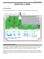
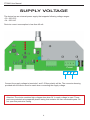
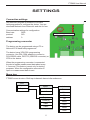
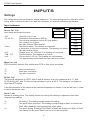
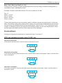
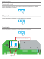
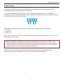
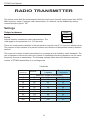
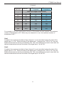
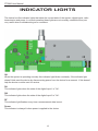
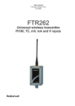
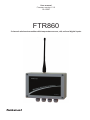
User manual
Firmware version V1.0
10.4.2007
FTR860
2 channel wireless transmitter with temperature sensor, mV, mA and digital inputs
Nokeval
FTR860 User Manual
INTRODUCTION
FTR860 is a two channel transmitter for temperature sensor, mV and mA inputs housed in a field
enclosure. Measured values are transmitted using license free 433.92 MHz frequency band (ISM)
so it can be freely used, for example, almost in whole Europe. The transmitter has a whip antenna
for radio coverage up to 200 meters in free space. The transmission interval is programmable and
can be set from four seconds to over four minutes.
FTR860 has also two digital inputs (0-5 VDC or 0-230 VAC). The device supports both 24 VDC
and 230 VAC supply voltages.
Contents
Introduction .................................................................................................................................
Installing .....................................................................................................................................
Supply voltage ............................................................................................................................
Settings ......................................................................................................................................
Inputs ..........................................................................................................................................
Radio transmitter ........................................................................................................................
Indicator lights ............................................................................................................................
Specifications .............................................................................................................................
Manufacturer
Tel: +358 3 3424800
Fax: +358 3 3422066
Web: www.nokeval.com
Technical support: [email protected]
Nokeval Oy
Yrittäjäkatu 12
FI-37100 Nokia
Finland
2
2
3
4
5
6
10
12
13
FTR860 User Manual
INSTALLING
Connections
For more detailed information about connections see chapters Supply Voltage and Inputs.
3PIN POL programming connector
Antenna
1 2 3 4
RTD
1 2
1 2 3 4
1 2 3 4
Input 1
Input 2
34
RTD
mV/TC
3 4
+ com/-
Digital Inputs
mA
3 4
DI1 DI2
1 2 3 4
+ -
4...230 VDC/VAC
Both channels can be configured
to any supported input
1 2 3 4
Power
1 2 3 4
20...250 VDC
24...250 VAC
Connecting the antenna
The antenna is connected to the BNC connector at the top side of the case. The antenna can be
either directly connected to the BNC connector of the device or alternatively a 50 ohm coaxial
cable (RG-58) with BNC connectors can be used to connect the antenna to the device.
First align the female connector’s two guideposts to the male connector’s channels. Then press
the BNC connector in and lock the connector by rotating the male connector’s outer ring clockwise.
If needed, the antenna can be removed by rotating the ring counter clockwise and then pulling out
the antenna.
3
FTR860 User Manual
SUPPLY VOLTAGE
The device has an universal power supply that supports following voltage ranges:
• 20...250 VDC
• 24...250 VAC
Device’s current consumption is less than 40 mA.
1 2 3 4
Power
1
2
3
4
Connect the supply voltage to terminals 1 and 3. Either polarity will do. The connector housing
provided with the device must be used when connecting the supply voltage.
Attention! The device contains high voltages also when 24 V supply voltage is used. These
parts are protected using separate plastic casing that contains no user serviceable parts. Do
not open this protective casing.
4
FTR860 User Manual
SETTINGS
Connection settings
Use Mekuwin program or Nokeval 6790 hand
held programmer to configure the device. You can
download Mekuwin from Nokeval’s web site for free.
Communication settings for configuration:
Baud rate
9600
protocol
SCL
address
0
Programming connector
Programming connector
The device can be programmed using a PC or
Nokeval 6790 hand held programmer.
The device has a 3PIN POL programming
connector. Use POL-3PIN adaptor to connect a
POL-RS232 cable, DCS772 (USB-POL converter) or
6790 to the device.
When the programming connector is connected
the device sends measurement data about every
1.3 second. This feature is ment only for testing
purposes. When the configuration connection is
open no measurement data is sent.
Menu tree
FTR860 menu structure. Both input channels have similar submenus.
Conf
Inputs
Output
Inputs
In1
In2
Output
Period [s]
Gate1
Gate2
In1
Sensor
Wires
R0
Pts
Mea1
Sca1
Mea2
Sca2
5
FTR860 User Manual
INPUTS
Settings
The configuration menu is divided in several submenus. The input settings are in a submenu called
Inputs, which is further divided in In1 and In2 submenus. In1 and In2 submenus are identical.
Input submenu
Inputs
Sensor (In1, In2)
Input range and sensor selection.
• Off:
• Pt, Ni, Cu:
• Ohm:
• mV:
• TcB…TcT:
• mA:
In1
In2
Channel is not in use.
Resistance thermometers (RTD’s).
The nominal resistance is set in R0 (see below).
The reading is in Celsius.
See also sections Wires and R0.
Resistance inputs. The resistor is connected
in three-wire or four-wire connection. The reading is in ohms.
See also section Wires.
Voltage input -30...2000 mV. The reading is in millivolts.
Thermocouples. The reading is in Celsius.
Current input 0..25 mA. The reading is in milliamperes
The appropriate jumper inside the case has to be closed.
In1
Sensor
Wires
R0
Pts
Mea1
Sca1
Mea2
Sca2
Wires (In1, In2)
RTD connection method. Only visible when RTD or Ohm input is selected.
• 2:
• 3:
• 4:
two-wire connection
three-wire connection
four-wire connection
R0 (In1, In2)
The nominal resistance of a RTD. With Pt and Ni sensors, this is the resistance at 0 °C. With
Pt100 set R0=100. With Cu the nominal resistance is given at 25°C. This setting is not visible on
other than RTD inputs.
If the real resistance of the sensor at the nominal temperature is known, it can be fed here, in order
to cancel the sensor error.
Pts (In1, In2)
Number of scaling points. The scaling means converting the reading to represent some other
(engineering) reading.
• 0:
• 1:
• 2:
No scaling. The reading equals measured reading.
One point offset correction. The reading corresponding to Mea1 is scaled to be
Sca1 when displayed, using appropriate offset value.
Two point scaling. Readings from Mea1 to Mea2 are scaled to be Sca1 to Sca2.
Any values can be used, these have not to be the end points.
6
FTR860 User Manual
Mea1, Sca1, Mea2 and Sca2 (In1, In2)
Scaling points. Visibility of these settings depends on the Pts setting. Unscaled reading Mea1 is
converted to Sca1, and Mea2 to Sca2.
Example: Pressure transmitter sends 4-20 mA for pressures 0-6 bar.
Pts = 2
Mea1 = 4 (mA)
Sca1 = 0 (bar)
Mea2 = 20 (mA)
Sca2 = 6 (bar)
These scaling points can be conveniently used to calibrate a sensor-transmitter pair in a thermal
bath. First set the scaling off by setting Pts=0. Apply one or two known temperatures to the sensor
and write down the displayed and the real temperatures. Then set Pts to 1 or 2 depending on the
number of calibration points, and write the first reading in Mea1 and the real temperature in Sca1.
And the same with Mea2 and Sca2 if two points are to be calibrated.
Connections
Analog input signals are connected to connectors Input 1 and Input 2.
RTD and resistance inputs (ohm, Pt100, etc)
two-wire connection
If the sensor has two wires, connect them to terminals 2 and 4.
1
2
3
4
RTD
three-wire connection
If the sensor has two wires the same color, connect these wires in terminals 3 and 4, and the third
wire in terminal 2.
1
2
3
4
RTD
four-wire connection
Four-wire connection: Connect the other end of the sensor in terminals 1 and 2, and the other in
terminals 3 and 4.
1
2
3
RTD
7
4
FTR860 User Manual
Thermocouple inputs
Connect the positive wire (K type: green or brown) of the thermocouple to terminal 3 and the
negative (white or blue) to terminal 4.
1
2
3
+
4
Tc
Voltage inputs
Connect the positive wire to terminal 3 and the negative wire to terminal 4.
1
2
3
+
4
mV
Current inputs
Connect the positive wire to terminal 3 and the negative wire to terminal 4.
1
2
3
+
4
mA
Close the channel’s mA jumper.
Open
Closed
mA jumpers
8
FTR860 User Manual
Digital inputs
The digital inputs of this device are designed for slow signals and wide voltage range. The
measurement cycle is approximately 1.3 seconds.
Connect the digital input 1 to terminals 1 and 2. Respectively digital input 2 is connected to
terminals 3 and 4. Either polarity will do. The connector housing provided with the device must be
used when connecting the digital inputs.
1
2
3
DI1
4
DI2
Both direct and alternating voltages can be connected to digital inputs. For example:
0 / +5 VDC
0 / +24 VDC
0 / 230 VAC
Input state is interpret as ”off” if the voltage between the terminals is less than 2 volts and ”on” if
the voltage is over 4 volts.
Maximum allowed voltage difference between the terminals is 330 VDC or 230 VAC. The
insulation between the digital inputs does not fulfill the requirements set for double insulation
or reinforced insulation. Therefore, no dangerous voltages can be applied to the other digital
input if the other is in contact with a user accessible part.
Digital inputs can also be used as a threshold condition to sending measurement data
using radio. For more information about this in the chapter Radio transmitter.
9
FTR860 User Manual
RADIO TRANSMITTER
The device sends both the measurement data from both input channels using license free 433.92
MHz frequency range. If needed, radio transmission of a channel can be disabled by setting
channel’s sensor type to ”Off”.
Settings
Output
Output submenu
Period
Period
Interval between consecutive radio transmissions. The
valid range for the parameter is 4...254 seconds.
Gate1
Gate2
There is a small random variation in the transmission interval (max 5.3 % from the defined value).
The purpose of this variation is to prevent continuous collisions of data packets send by different
devices.
The maximum number of radio transmitters in a coverage area is limited by radio standards. The
use of repeaters reduces the maximum number of transmitters because repeaters use the same
frequency channel as transmitters. The following example table shows the allowed maximum
number of FTR860 transmitters in a coverage area.
2 channels
Transmission
Interval (s)
5
10
20
30
40
50
60
90
120
240
Receiver and
Receiver and
1 repeater
2 repeaters
Maximum number of transmitters
10
5
3
20
10
7
39
20*
13
59
29
20
78
39
26
98
49
33
118
59
39
176
88
59
235
118
78
471
235
157
Receiver
10
FTR860 User Manual
1 channel
Transmission
Interval (s)
5
10
20
30
40
50
60
90
120
240
Receiver and
Receiver and
1 repeater
2 repeaters
Maximum number of transmitters
26
13
9
53
26
18
105
53**
35
158
79
53
211
105
70
263
132
88
316
158
105
474
237
158
632
316
211
1263
632
421
Receiver
For example, if you have transmission interval of 20 seconds and one repeater, the maximum
number of transmitters is 20*. When only one channel is in use, the maximum number of
transmitters is 53**.
Gate1
If enabled, the measurement data of input channel 1 is not transmitted unless the state of the
digital input 1 is ”On”. When the state of the digital input 1 changes from ”Off” to ”On” the next
finished measurement result is immediately sent. The next measurement result is sent after the
defined transmission interval if the state of the digital input 1 is still ”On”.
Gate2
If enabled, the measurement data of input channel 2 is not transmitted unless the state of the
digital input 2 is ”On”. When the state of the digital input 2 changes from ”Off” to ”On” the next
finished measurement result is immediately sent. The next measurement result is sent after the
defined transmission interval if the state of the digital input 2 is still ”On”.
11
FTR860 User Manual
INDICATOR LIGHTS
The device has five indicator lights that show the current state of the system, digital inputs, radio
transmission and power. In normal operation these lights are not normally needed but they are
very useful when troubleshooting error conditions.
OK
DI1
DI2
RF
Power
OK
When the system is operating normally this indicator light blinks constantly. If the indicator light
doesn’t blink reset the device by disconnecting power from the device for a moment. If this doesn’t
help the device must be sent for service.
DI1
This indicator lights when the state of the digital input 1 is ”On”.
DI2
This indicator lights when the state of the digital input 2 is ”On”.
RF
This indicator light flashes every time a measurement data is sent.
Power
This indicator is always lit when power is applied to the device.
12
FTR860 User Manual
SPECIFICATIONS
Radio transmitter
Input
Pt100
Range
Accuracy
Thermal drift
-200...700 °C
0.05% rdg + 0.25 °C
0.02 °C/°C
Ni100
Range
Accuracy
Thermal drift
-60...180 °C
0.05% rdg + 0.25 °C
0.02 °C/°C
Cu10
Range
Accuracy
Thermal drift
-200...260 °C
0.05% rdg + 0.25 °C
0.02 °C/°C
Thermocouples
TC
B
C
D
E
G
J
K
L
N
R
S
T
Thermal drift
Accuracy
range
lin.error
400…1700°C
±0.3°C
0…2300°C
±0.5
0…2300°C
±1
-100…900°C
±0.2
1000…2300°C ±2
-160…950°C
±1
-150…1370°C
±0.5
-150…900°C
±0.5
0…1300°C
±0.1
0…1700°C
±0.5
0…1700°C
±0.5
-200…400°C
±1
0.02°C / °C (ref 25°C)
0.05% rdg + 0.5°C + lin.error +
thermal drift
mV
Range
Accuracy
Thermal drift
-30...2000 mV
0.05% rdg + 0.01 mV
50 ppm/°C
mA
Range
Accuracy
Thermal drift
0...25 mA
0.008 mA
50 ppm/°C
Antenna
Connector:
50 ohm female BNC connector
Standard antenna: Quarter-wave whip antenna
(BNC connector)
Frequency range: License free 433.92 MHz subband f
according to ERC/REC/70-03
Power supply
Voltage:
24 VDC/230 VAC ±15%
Current consumption: max 40 mA
Environment
Operating temperature: -30...+60 °C
Protection class:
IP65
Configuration
Connector:
Protocol:
Configuration:
3PIN POL programming connector
Nokeval SCL protocol
PC with Mekuwin for Windows 98...XP
or 6970 hand held programmer
Regulations
EMC directive
• EMC immunity EN 61326
• EMC emissions EN 61326, class B
R&TTE directive
• EN 300 220 class 3,
Transmitter power class 8 (10 mW)
• EN 301 489
• EN 300 339
Measures
Case
180 mm x 130 mm x 60 mm
(WxHxD)
Antenna
178 mm, Ø 8...16 mm
13
FTR860 User Manual
14