1
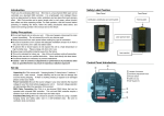
EPM-153
PWM signal
amplifier for
LED lighting
Thank you for the confidence you have placed in us by purchasing our product. It is an
incredibly versatile device of high quality and reliability. However, in order to benefit from its
capabilities and failure-free maintenance we strongly recommend following the instruction
included in the manual.
Use this device exclusively with its particular applications. It should be installed by qualified
personnel only. The manufacturer is not liable for improper handling, connecting or operating
the unit in any way that does not comply with the manual or technical and safety regulations.
This unit is designed mainly for stage applications. If used otherwise comply with the technical
and safety regulations applicable in the country where the product is used.
IMPORTANT SAFETY INSTRUCTIONS
•
•
•
•
•
•
•
•
No user serviceable parts inside; refer servicing to qualified personnel
To reduce the risk of fire or damage this device must not be exposed to rain and moisture.
Installation and connections can only be made with power off
Cleaning only with compressed air or chemical dry cleaners after power supply has
been disconnected.
This unit is to be powered from constant voltage supply equipped with short circuit,
over load and over voltage protection.
Unplug this apparatus during lightning storms or when unused for long periods of time.
This device may generate heat during operation thus requires proper ventilation. Do
not install near any heat sources (radiators, stoves or other heat generating devices).
Observe polarity and output current load specified in the manual.
Technical specifications and appearance subject to change without notice. The information
contained herein is correct at the time of printing. No part of this manual may be reproduced
or transmitted in any form or by any means, electronic or mechanical, including photocopying and recording of any kind, for any purpose without written permission of Enterius.
Latest manuals and declarations of conformity for all our products are available for
download on our webpage:
http://enterius.pl
Electrical equipment marked with this symbol may not be disposed of in European public disposal
systems. In conformity with European local and national regulations (EU Directive 2002/96/EC),
European electrical equipment users must now return old or end-of-life equipment to the manufacturer for disposal at no charge to the user.
Note: For return for recycling, please contact the equipment manufacturer or supplier for instructions on how to return end-of-life equipment for proper disposal.
USER MANUAL
EPM-153 is a professional 3 channel PWM signal amplifier (often referred to as repeater)
which can co-operate with LED (or any other low voltage) light controllers or dimmers outputting Pulse Width Modulation (PWM) signal. Thanks to special output channels with a very
high current capacity (3 x 15 A), the unit enables connecting low voltage light sources with
maximum power of up to 1080 W (at 24 V), which allows the construction of very large lighting installations, with a use of only one RGB controller or dimmer. Furthermore, many PWM
amplifiers can be connected to one control unit – as a result we can gain control of truly
considerable power.
EPM-153 has 3 inputs fully insulated galvanically which automatically detect the operating
polarity of the connected control device. Thanks to that, this device can work with controllers with a common plus or minus. In addition, the inputs are equipped with digital circuits filtering interference and improving the PWM shape which accesses the amplifier; this ensures
that even with very long connection cables and signal distorted by the receivers connected
directly to the controller, the signal is regenerated in this unit.
EPM-153 has 3 high current outputs with maximum load capacity of 15 A each. These inputs
can be connected in parallel (for example when operating with EC-11D dimmers) in order
to obtain 1 channel with load capacity of 45A!
The EPM-153 amplifier operates correctly within a wide range of voltage (input and supply)
from 8 up to 24 VDC. Due to operation with Pulse Width Modulation, it is absolutely necessary to use highest quality stabilised power units. The unit should also be located in such a
place which would ensure that the cables delivering high current to the LED equipment (or
other low voltage receivers) were as short as possible. These cables should not be run with
any other installations due to generation of interference. It is very important to choose appropriate size (cross-section) of all cables delivering high currents, especially that such high
currents require the cable cross-section to considerably expand along with the distance.
The table below depicts examples of recommended cable cross-sections for a number of
distances and for two current values. During the design works of the RGB four-wire circuit
(common plus) it should be remembered that the current is three times higher in the plus
supplying wire, and as a result its cross section should be appropriately larger.
Distance
between LED
and EPM-153
1m
2m
5m
10m
15m
30m
Cable cross-section for
10A (mm2)
Cable cross-section for
15A (mm2)
0.5
1.5
4.0
6.0
10.0
16.0
0.75
1.5
4.0
10.0
16.0
25.0
3
ASSEMBLY AND CONNECTIONS
The device is equipped as standard to be screwed on with M4 bolts by means of 4 corner
apertures with a diameter of 4.2 mm, located on the PCB. Depending on the assembly location, spacing sleeves (not provided in the set) or snap-action pins can be used. As an option,
we also offer special assembly ties for the bus bar TH-35 (also referred to as TS-35), which
allow the attachment to be installed in electrical switching stations. During operation with
maximum load the EPM-153 device can heat up significantly, so it is vital to supply appropriate ventilation, while the device should not be located directly next to other heat sources or
materials sensitive to increased temperature.
The power amplifier is adapted to be installed indoors, and if it is required to be installed outside, there should be additional casing used with a protection level of at least IP54.
The diagram below depicts the most typical method of connecting the unit. In some instances, the inputs (1, 2, 3) and outputs (1, 2, 3) of the device can be connected in parallel,
however, in regards to large installations with considerable power, we recommend using
a few amplifiers and using a distributed layout in order to reduce the current which flows
through the single wires. Also, cables with smaller cross-sections can then be used and interference, generated by switching between power levels during the Pulse Width Modulation,
can also be limited.
Power
supply
+
RGB
R
controller G
B
+
LED light source
R adjusted to the
G correct operatB ing voltage
+
LED light source
adjusted to the
correct operating voltage
+
Power supply +
4
Cable appropriate for high current
LED
dimmer
CAUTION!
If this PWM amplifier is the only device connected to the controller (there are no light
sources connected directly to the controller), there might be a need to connect
additional resistors of 200R/0.25W to the controller’s outputs. The lack of resistors may
result in extended switching time of the unloaded output MOSFET transistors in the
control equipment (depending on its construction and type) and render the unit’s
operation to be less precise.
Technical specification
Supply voltage: Current consumption without load: Total power consumption: Output Current capacity: The control voltage range: Frequency PWM control signal: Cross section of output channels cubes: Dimensions: 8-24VDC
120mA
max. 45A
15A/kanał
8-24VDC
0.1-5kHz
10mm2
90x120x25
5
Notes
6
date of claim
date of completion
repair
number
repair description
service stamp and signature
WARRANTY
1. ENTERIUS warrants the mechanical and electronic components of this product to be free of
defects in material and workmanship if used under normal operating conditions for a period of
5 (five) years from the original date of retail purchase. If the product shows any defects within
the specified warranty period and that defect is not excluded under further clauses, ENTERIUS
or its Resellers shall, at its discretion, either replace or repair the product using suitable new or
reconditioned product or parts. In case manufacturer decides to replace the entire product, this
warranty shall apply to the replacement product for the remaining initial warranty period of 5
(five) years from the date of purchase of the original product.
2. This warranty is valid only if you purchased the product from ENTERIUS authorized Reseller in the
country of purchase. Please retain your proof of purchase as this warranty is void without such
proof (invice, receipt,etc.)
3. This warranty does not cover the product if it has been electronically or mechanically modified
in any way. Such modification/adaptation void warranty, regardless of whether it was carried
out properly or not. Under the terms of this warranty, ENTERIUS shall not be held responsible for
any cost resulting from such a modification/adaptation.
4. This warranty is invalid if the factory-applied serial number has been altered or removed from
the product.
5. Damage/defects caused by the following conditions are not covered by this warranty:
• improper handling, neglect or failure to operate the unit in compliance with the instructions given in ENTERIUS service manuals
• connection or operation of the unit in any way that does not comply with the technical or
safety regulations applicable in the country where the product is used
• damage/defects caused by acts of God/Nature (accident, fire, flood, etc) or any other
condition that is beyond the control ENTERIUS
6. Any repair of the unit carried out by unauthorized personnel (user included) will void the warranty.
7. ENTERIUS shall have no liability to the buyer under this warranty for any consequential or indirect loss or damage of any kind. In no event shall the liability of ENTERIUS under this limited
warranty exceed the invoiced value of the product.
8. The defective product shall be delivered to ENTERIUS or its Reseller at the expense of the product owner.
Unit model/type
Serial number
Date of purchase
Dealer stamp
Purchase document number
Purchaser signature: .........................................