1
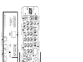
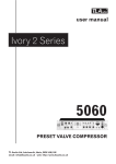
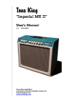
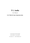
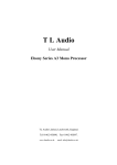
®
TLAudio
user manual
Ivory 2 Series
5052
STEREO VALVE PROCESSOR
TL Audio Ltd, Letchworth, Herts, SG6 1AN, UK
email: [email protected] web: http://www.tlaudio.co.uk
CONTENTS
1
INTRODUCTION
2
PRECAUTIONS
3
INSTALLATION
3.1
A.C. Mains Supply
3.2
Microphone Input
3.3
Compression
Balanced Line Input
3.4
Unbalanced Line Input
3.5
Instrument Input
3.6
Insert Points
3.7
Sidechain Insert Points
3.8
Line Outputs
3.9
Nominal Operating Level
3.10
Ventilation
3.11
Rear Panel
4
OPERATION
4.1
Input Stage
4.2
Microphone Input
4.3
Line Input
4.4
Instrument Input
4.5
30dB Pad Switch
4.6
90Hz Filter
4.7
Phase Reverse
4.8
Drive and Peak LEDs
4.9
Output Gain
4.10
Bypass
4.11
What Is Compression?
4.12
Why Valve Compression?
4.13
Overview of Compressor
Operation
4.14
Threshold
4.15
Ratio
4.16
Attack and Release
4.17
Knee
4.18
Gain Make Up
4.19
Compressor On
4.20
EQ S/C & Frequency Conscious
4.21
Meter
4.22
Equalisation
4.23
Cut/Boost Control
4.24
Frequency Control
4.25
Q (Bandwidth) Control
4.26
Shelving EQ
4.27
EQ On
4.28
EQ Pre
4.29
Output Limiter
4.30
Stereo Link Modes
4.31
Optional DO-2 Digital
Output Card
5
GETTING STARTED
5.1
Connections
5.2
In Use – Mono tracking
mode
5.3
In Use – Stereo mixdown
mode
6
FAQ
7
SPECIFICATIONS
8
SERVICE
1.
INTRODUCTION
Congratulations on purchasing the Ivory 5052 Stereo Valve Processor by TL Audio!
The Ivory 2 Series consists of a range of hybrid valve signal processors, which utilise
low noise solid state electronics in conjunction with classic valve circuitry to produce
audio processing units offering very high quality signal paths with the unique valve
audio character. The units offer comprehensive control facilities, whilst remaining
straightforward to operate, and represent excellent value for money.
The 5052 is a dual channel processor with mic, line and instrument inputs, and
features a compressor, four band equaliser and peak limiter on both channels. The
compressor, equaliser and limiter stages can be operated in ‘dual mono’ or ‘linked
stereo’ modes, making the 5052 equally powerful for both mono/stereo tracking and
final stereo mix processing. A pair of illuminated VU meters monitor the input level,
output level, compressor gain reduction and limiter gain reduction for both channels.
The optional DO-2 digital output card allows 24-bit analogue to digital conversion
via an RCA phono type SPDIF output, with selectable 44.1 or 48 kHz sample rates
and the option to clock the converter to an external word clock source.
The block diagram of the 5052 is shown in Figure 1. A solid state, electronically
balanced input amplifier is used to achieve state of the art performance with very low
noise, low distortion and wide bandwidth. An ECC83/12AX7A triode valve stage (run
from a stabilised 150v DC supply) is used as a second stage voltage amplifier, to
obtain the classic valve sound and gradual overdrive characteristics. The preamp
stage also features 48V phantom power, phase reverse, 30dB pad and a high pass
90Hz filter. A Drive LED gives a visual indication of the signal level through valve
stages (and thus the amount of ‘warming’ taking place) while a Peak LED warns that
clipping is about to occur, and this monitors the signal at key points in the audio
path.
The compressor section offers fully variable control of threshold, ratio,
attack/release and gain make-up, and both hard and soft knee options are
available. A ‘Hold’ facility reduces LF distortion, and a side chain insert point is
provided for frequency conscious compression. Like all other TL Audio
compressors, the gain control element of the 5052 compressor stage is based
around a special transconductance amplifier, which avoids the use of VCAs and helps
contribute to the smooth, open sound of the unit, along with a triode valve stage
that forms part of the gain make-up circuit.
A four band valve EQ stage is included, providing up to 15dB of cut or boost on
each band. The LF and HF bands provide swept frequency controls with a choice of
shelving or peaking response. The LM and HM bands are fully parametric with
variable control of gain, frequency and bandwidth. The ‘EQ PRE’ switch places the
EQ ahead of the compressor in the signal path, while the ‘EQ S/C’ switch places the
EQ entirely in the compressor sidechain circuit, for frequency conscious
compression. A triode valve stage is located just after the four EQ filter stages.
A peak output limiter is included, and this is located after the output level control.
This limiter has a high ratio and a fast attack time, making it ideal for prevention of
overload in digital recorders. A threshold control is provided, along with an LED
indication of when the limiter threshold is exceeded.
Mic and line inputs are provided on electronically balanced XLR connectors, and the
line input is duplicated on an unbalanced mono 0.25” jack connector. Balanced and
unbalanced line outputs are provided (on XLR and jack respectively) and these can
be used simultaneously. The operating level of the line input can be shifted from 10dB to +4dB (unbalanced) or +4dB to +18dB (balanced) via a rear panel switch,
allowing the 5051 to accept very high levels - such as those from a digital recorder. A
pair of high impedance front panel instrument inputs are also provided, thus allowing
guitars, basses and keyboards to feed directly into the 5052, removing the need for
a separate DI box. Finally, balanced insert points (located after the preamp stage
but before the processing stages) and compressor sidechain insert points are
featured. The former allows other external units to be patched into the 5052 signal
path, while the latter permits frequency conscious compression to be performed by
patching in an external equaliser.
Please read this manual fully before installing or operating the 5052.
2.
PRECAUTIONS
The Ivory 5052 requires very little installation, but like all electrical equipment, care
must be taken to ensure reliable, safe operation. The following points should always
be observed:
- All mains wiring should be installed and checked by a qualified
electrician,
- Ensure the correct operating voltage is indicated on the rear panel
before connecting to the mains supply,
- Never operate the unit with any cover removed,
- Do not expose to rain or moisture, as this may present an electric
shock hazard,
- Replace the fuse with the correct type and rating only.
Warning: This equipment must be earthed.
PEAK
INST
100
dB
30
EQ
PRE
Hz
PH REV
0
dB
+20
+12
LIMIT
LIMITER SECTION
dB
LIMITER
ON (PULL)
+5
0
1
LIM
48
0
INST
INPUT 2
COMP2
+10
dB -20
2
1:5
MIC
MIC
-30dB
SLOW
12
90Hz
20
GMU
INST
PEAK
5
dB
EQ
S/C
RELEASE
0
FAST
KNEE
SLOW
LINE
INPUT 2
DRIVE
MIC
48V
1:10
1:30
RATIO
ON
ATTACK
1:1.5
FAST
HARD
SOFT
INPUT GAIN BYPASS
0
LF
dB
Hz
1K
PH REV
0
dB
+5
dB
+12
LIMIT
+20
LIMITER
0
ON (PULL)
+15
OUTPUT
GAIN
- oo
0
+15
12K
-15 dB
HF
6K
EQ
ON
3K
20K
0
+15
6K
-15 dB
1
+18dBu
2
2
LINE INPUT (BALANCED)
+4dBu
1
MIC INPUT (BALANCED)
MIC INPUTS
PK
SHLV
Hz
HM
2K
12K
1K
Hz
0
1K
+15
3K
LM
Hz
-15 dB
100
EQUALISER 2
+4dBu
LINE INPUTS
LINE INPUT
(UNBALANCED)
-10dBu
2
1
300 300
+15
+60(+20)
+38 (0)
MIC(LINE)
30
EQ
PRE
PK
SHLV
-15 dB
+16(-20)
100
RETURN 2
LINE INPUT LEVEL
SERIAL NUMBER
Manufactured by TL Audio Limited, England.
SEND 2
INSERT
(BALANCED +4dBu)
RETURN 1
INSERT SEND/RETURN POINTS
SEND 1
5052 STEREO VALVE PROCESSOR
-10
THRESHOLD
VU METERS
POWER
ON
2
COMP G/R
LIM G/R
+10dB
METERS
O/P
EQ
STEREO LINK SECTION
COMP
STEREO MODE
(CH1 MSTR)
I/P
FIG 2: FRONT PANEL
+15
12K
-15 dB
0
6K
HF
+15
6K
-15 dB
0
2K
20K
3K
EQ
ON
CAUTION
ATTENTION
RISK OF ELECTRIC SHOCK
DO NOT OPEN
kHz
W/CLOCK
IN
RISQUE DE CHOC ELECTRONIQUE
NE PAS OUVRIR
SPDIF OUTPUT
44.1
2
OUTPUT (BALANCED +4dBu)
1
LINE OUTPUTS
1
OUTPUT
(UNBALANCED -10dBu)
OPTIONAL DO-2 OUTPUT CARD
FIG 3: REAR PANEL
PK
SHLV
Hz
HM
1K
12K
1K
Hz
0
Hz
2
EQ SECTION
EQUALISER 1
3K
LM
+15
+15
OUTPUT
GAIN
100
-15 dB
- oo
300 300
+15
1K
PK
SHLV
-15 dB
0
LF
+60(+20)
+38 (0)
MIC(LINE)
INPUT GAIN BYPASS
SLOW
12
+16(-20)
20
GMU
90Hz
-30dB
MIC
INPUT SELECTOR SWITCH
DRIVE
LINE
INPUT 1
MIC
5
dB
EQ
S/C
RELEASE
0
FAST
KNEE
SLOW
HARD
SOFT
1
SIDECHAIN INSERT
(UNBALANCED)
FUSE T1AL 250V
230V~30VA
115V~30VA
IEC INLET
COMPRESSOR SECTION
ON
1:10
1:30
RATIO
FAST
ATTACK
1:1.5
1:5
MIC
48V
-10
THRESHOLD
0
dB -20
COMP1
+10
INST
INPUT 1
INSTRUMENT INPUT
WARNING - ATTENTION
THIS APPARATUS MUST BE EARTHED.
FOR CONTINUED PROTECTION
AGAINST RISK OF FIRE, REPLACE ONLY
WITH SAME TYPE AND RATING OF FUSE.
UTILISER UN FUSIBLE DE RECHANGE DE
MEME TYPE ET CALIBRE
WARNING
TO REDUCE THE RISK OF FIRE
OR ELECTRICAL SHOCK,
DO NOT EXPOSE THIS EQUIPMENT
TO RAIN OR MOISTURE
JACK (UNBALANCED): TIP = +VE, SLEEVE = GND.
JACK (BALANCED): TIP = +VE, RING = -VE, SLEEVE = GND.
JACK (UNBALANCED INSERT): TIP = SEND, RING = RETURN, SLEEVE = GND.
XLR: PIN 1 = GND, PIN 2 = +VE, PIN 3 = -VE.
SIDECHAIN INSERT POINTS
5052
STEREO VALVE
PROCESSOR
3.
INSTALLATION
3.1
AC Mains Supply.
The unit is fitted with an internationally approved 3 pin IEC connector. A mating
socket with power cord is provided with the unit, wired as follows:
Brown: Live.
Blue:
Neutral.
Green/Yellow: Earth (Ground).
All mains wiring should be performed by a qualified electrician with all power switched
off, and the earth connection must be used.
Before connecting the unit to the supply, check that the unit is set for the correct
mains voltage. The unit is internally set for 110-120V 60Hz or 220-240V 50Hz
operation, and should only be changed by an authorised service centre. The mains
fuse required is 20mm anti-surge, 1AT rated at 250V. If it is ever necessary to
replace the fuse, only the same type and rating must be used. The power
consumption of the equipment is 30VA.
Warning: attempted operation on the wrong voltage setting, or with an incorrect
fuse, will invalidate the warranty.
3.2
Microphone Input.
The microphone input is via 3 pin female XLR connector, suitable for balanced or
unbalanced microphones. The mating connector should be appropriately wired as
follows for balanced or unbalanced operation:
Balanced inputs:
- Pin 1 = Ground (screen).
- Pin 2 = Signal Phase (also known as “+” or “hot”).
- Pin 3 = Signal Non-Phase (“-” or “cold”).
Unbalanced inputs:
- Pin 1 = Ground (screen)
- Pin 2 = Signal Phase (“+” or “hot”).
- Pin 3 = Signal Ground.
3.3
Balanced Line Input.
The 5052 has a 3 pin XLR socket on the rear panel, which will accept both balanced
and unbalanced line level inputs. The mating connector should be appropriately
wired as follows:
Balanced inputs:
- Screen = Ground,
- Tip = Signal Phase (“+” or “hot”),
- Ring = Signal Non-Phase (“-” or “cold”).
Unbalanced inputs:
- Screen = Ground,
- Tip = Signal Phase (“+” or “hot”),
- Ring = Ground.
When using unbalanced signals, the signal ground may be obtained by linking pins 1
and 3 in the mating XLR connector. If this connection is not made, a loss in level may
result.
3.4
Unbalanced Line Input.
An unbalanced line level input at a nominal level of -10dBu is also provided, on a
0.25” mono jack socket. The mating plugs should be wired as follows:
- Tip
= Signal Phase (“+” or “hot”).
- Screen = Ground.
3.5
Instrument Input.
Each channel has a 0.25” jack socket on the front panel (see Figure 2). A 2 pin
(mono) jack plug is required, which should be wired as follows:
- Tip = Signal Phase (“+” or “hot”),
- Screen = Ground.
Good quality screened cable should be used, particularly for microphone or low level
sources, to prevent hum or noise pickup.
3.6
Insert Points.
The insert points are interfaced via a pair of 3 pin, 0.25” jack sockets on the rear of
the unit. These points (not to be confused with sidechain insert points – see section
3.7) are located after the initial preamp stage but before the compressor stage, and
allow an external device to be patched into the 5052 signal path.
One socket is marked ‘Send’ (which connects to the external device’s input) while
the other is marked ‘Return’ (which connects to the external device’s output).
The pin connections for both Send and Return are:
- Sleeve = Ground,
- Tip = Signal Phase (“+” or “hot”),
- Ring = Signal Non-Phase (“-” or “cold”).
The insertion points are balanced, and operate at a nominal level of +4dBu.
3.7
Sidechain Insert Points.
The sidechain insert points allow access to the 5052 compressor sidechain (i.e. for
frequency conscious compression – see section 4.20) and are interfaced via a 3 pin,
0.25” switched jack socket on the rear of the unit. The pin connections are:
- Sleeve = Ground,
- Tip = Send,
- Ring = Return.
The sidechain insert point is unbalanced, and operates at a nominal level of -2dBu .
If used as an additional send only (e.g. as a send to a tape machine or monitor
mixing desk), the Tip and Ring should be wired together, to preserve the signal path
through the insertion point. If connecting the 5052 sidechain insert to a patchbay it is
important to ensure that the ‘send’ and ‘return’ are connected together when not in
use – if the send/return circuit is left open then this can cause incorrect operation of
the compressor stage.
3.8
Line Outputs.
The line outputs are provided on a balanced XLR connector, and also via an
unbalanced _” jack. Balanced operation is always preferable to maintain maximum
headroom and signal to noise ratio, but can only be used if the following equipment
is also capable of balanced operation:
Balanced outputs:
- Screen = Ground,
- Tip = Signal Phase (“+” or “hot”),
- Ring = Signal Non-Phase (“-” or “cold”).
Unbalanced outputs:
- Screen = Ground,
- Tip = Signal Phase (“+” or “hot”),
- Ring = Ground.
3.9
Nominal Operating Level.
A switch on the rear panel allows the line inputs to be matched to equipment at a
nominal operating level of +4dBu or -10dBu for unbalanced signals, and +18dBu or
+4dBu for balanced signals. Most professional equipment requires +4dBu
(approximately 1.2V rms), but some small mixing consoles, portable tape recorders or
domestic audio equipment require -10dBu (approximately 225mV rms). Digital
multitrack recorders have very high signal levels due to the digital scale of 0dBFS
usually matching +18dBu in the analogue domain. The 5052 is able to match the
operating level of such recorders, using the +18dBu setting. If the operating level is
not known, the switch should be set to the position which results in the best signal to
noise ratio and least noise while being able to handle high signal levels.
3.10
Ventilation.
The 5052 generates a small amount of heat internally, mainly due to the valve heater.
This heat should be allowed to dissipate by convection through the side grills, which
must not be obstructed. Do not locate the 5052 where it will be subject to external
heating, for example, in the hot air flow from a power amplifier or on a radiator.
3.11
Rear Panel.
The rear panel connectors are identified in Fig.3. Make sure that all settings, mains
and audio connections have been made as described above before attempting to
operate the equipment.
4.
OPERATION
4.1
Input Stage.
The Input Gain control sets the level of the mic, line or instrument input into the 5052
preamp stage. The signal source is selected by the 4-position switch adjacent to the
Input Gain control. Input choices are Mic 48V (for condenser microphones that
require phantom power), Mic (for dynamic or most ribbon microphones), Line and
Instrument. The Instrument input allows high impedance instruments such as guitars
or a bass etc to connect directly into the 5052 and eliminates the need for a Direct
Injection Box. A wide range of signals can be fed into the 5052, and the Input Gain
control also allows the valve stages to be driven to a variable degree. After the
preamp stage the signal passes through a triode valve stage positioned between the
input circuit and the compression stage. Increasing the input gain pushes more signal
level into the valve, thus generating more harmonic distortion and creating that
special “valve sound”. This is indicated by the yellow ‘Drive’ LED which will glow more
intensely as the level increases. At the same time the output level can be turned
down to preserve the same level at the output, so a choice of sounds is available.
For a more pronounced valve sound, turn up the input gain and reduce the output
gain, and vice versa for a cleaner sound. Don’t be afraid to push the 5052 hard!
As well as driving the valves harder, increasing the Input Gain control setting will also
have a pronounced effect on the amount of compression as the threshold will remain
constant as the input level increases. If the input gain is adjusted, the threshold can
be adjusted accordingly to maintain a similar amount of compression.
4.2
Microphone Input.
When using the 5052 with a microphone source, care should be taken not to apply
too much gain at the input. Start with the input gain control set to minimum, and the
output master at the mid-point (12 o’clock position). The input gain can then be
gradually increased until the VU meter registers about 0VU on normal signal level,
when set to read ‘I/P’. The master output level should then be adjusted to produce
the required output.
CAUTION:
Never switch phantom power on or off, or plug / unplug a
microphone with phantom power applied unless the output level control is turned
down. Failure to do so may result in a thump in your monitor loudspeakers or PA
system.
4.3
Line Input.
A line level signal should already be at about the correct operating level, but this may
be checked by monitoring the level with the VU meter set to ‘I/P’. The input gain
should be adjusted until the meter reads about 0VU at normal audio level.
4.4
Instrument Input.
The front panel instrument input socket is suitable for low level sources such as hi
impedance microphones, pick ups or passive guitars, and higher level sources such as
active guitars and keyboards. To cater for this wide variety of sources, the 5052 has
a large amount of gain available, and care should be taken to avoid applying
excessive input gain with a high level source.
4.5
30dB Pad Switch.
Occasionally - when using sensitive condenser microphones - the source signal may
be too loud for the input preamp. In this situation, to avoid any overloading or
distortion of the mic preamp stage, the 30dB pad can be used to reduce the input
gain to a more manageable level. The 30dB pad only applies to the microphone
input.
4.6
90Hz Filter.
The high pass filter switch restricts the low frequency response of the preamp, to
effectively remove rumble or LF noise from the signal. The filter can be useful in
restricting “popping” on vocals or even low frequencies caused by contact with
microphone stands or microphone cables. Popping is an undesirable thump that is
caused by close-miking certain spoken or sung letters, namely “P” or “B”. These
particular letters cause a sudden expulsion of air that can result in an audible thump.
As this thump has a lot of low frequency content the high pass filter can help to
reduce the problem, as can using a pop filter (a device usually made out of nylon
material similar to stockings) suspended in front of the microphone.
4.7
Phase Reverse.
The phase reverse switch allows correction of a phase error, which may have
occurred in microphone wiring or placement. Phase errors can be due to two
microphones picking up the same signal at the same time. An example of this problem
is when recording a snare drum with one microphone on the top snare skin and a
second microphone on the underside skin of the snare drum. Because the two
microphones are picking up the same signal at the same time, phase cancellation can
occur. By inverting the phase of one of the microphones this problem can be
rectified. A phase mis-match will probably manifest itself as an apparent loss of bass
content when two microphone signals are mixed together or fed to a stereo pair of
loudspeakers. If an error is suspected, it is a simple operation to check by phase
reversing each channel in turn. The phase reverse is active on mic, line and instrument
inputs.
4.8
Drive and Peak LEDs.
The yellow Drive LED provides a visual indication of the signal level through the valve
stages, and therefore the extent of “warming” or valve character being introduced.
The drive LED will gradually illuminate as the input level or gain is increased, over the
range +6dB to +16dB.
The red Peak LED operates as a conventional warning that clipping is about to
occur. The operating level of the entire signal chain is monitored, and the LED
illuminates when an internal level of around 19dB is reached. Normal operation would
be to set the input gain so that the drive LED is regularly illuminating, with occasional
lighting of the red Peak LED on transients.
If the input and output gain controls are set to their centre (0dB) positions, the
Peak LED will illuminate some 3dB after the Drive LED has reached its full intensity.
However, it is possible to add gain further down the chain (i.e. output level gain),
which will cause the Peak LED to illuminate at a lower level of Drive. This situation
implies that a high level of “clean” signal is present, without driving the valves hard.
4.9
Output Gain.
This controls the level at the 5052 outputs. The nominal level is 0dB at the centre
detented position. This control effectively acts like an output fader, and is very
useful when recording direct to tape or hard disc through the 5052. You may find
that some digital recorders require a good deal of input level in order to register a
0dB reading on their meters (+18dBu analogue usually matches 0dBFS in the digital
scale). This is normal, since many digital recorders are designed to preserve
headroom and keep the signal well below the 0dB clip point - thus preventing the
recorder distorting. The 5052 provides a further 15dB of gain at the output fader to
drive digital recorders. It is important to distinguish the difference between the
output gain knob and the gain make-up knob in the compressor section. The gain
make-up control is only active when the compressor is switched on. The output gain
control is always active but will have no effect on the compression characteristics of
the signal.
4.10
Bypass.
The Bypass switch is a convenient way of bypassing the compressor, EQ and limiter
sections on either channel so that the original and processed signals can be easily
compared. This avoids having to individually bypass each of these sections to hear
the original signal. Please note that all status LEDs remain active in these sections
even when bypassed, and the meters will continue to register any gain reduction
occurring.
4.11
What is Compression?
Compression is an essential but often misunderstood process in modern recording.
Put simply, compression reduces the difference between the loudest and the
quietest levels of an audio signal. This is known as reducing the “dynamic range” of
that signal and is a powerful tool for an engineer helping to avoid overloading,
distortion problems as well as raising the level of the quieter parts of the audio signal.
Before the introduction of compressors the only way this could be achieved was by
“gain riding”, whereby an engineer would control the fader manually in order to try
and anticipate very large levels (which might distort the signal) or very low levels
(which may get lost in noise). The introduction of compression devices meant that
this process could be controlled automatically, allowing the engineer to get on with
more productive jobs!
Many instruments and voices have a very wide dynamic range that need to be
controlled. A singer, for instance, may be singing quietly one moment and very loudly
the next, and unless compression is applied the vocal won’t “sit” correctly in the mix,
in addition to the problems of distortion on loud passages and noise on quiet ones.
Compressors effectively turn down the loud bits and turn up the quiet bits, to
achieve a more even and controllable level.
Compressors are often judged by their ability to control the dynamics without
creating noticeable audible side effects. Heavy compression can cause the signal to
pump or breathe with the onset and release of the compression. Some compressor
designs can dull the signal and lose the top end of the signal. The 5052 compressor
design, as with other TL Audio compressors, uses a technology based around a
transconductance amplifier rather than a VCA design. This transconductance
amplifier design is known for being able to retain the full frequency range and natural
character of the audio signal, even when compressing the signal quite heavily. The
Ivory 5052 is also capable of more severe compression based around the optional
Hard Knee mode if this is desired.
There are other benefits of compression as well as just controlling the peaks and
raising the quiet parts, applied properly, it can add punch and excitement to music,
as well as fattening up sounds and creating a more professional sounding recording.
With the 5052, you have the added benefit of valve stages in the signal path, which
create a warmth and presence just not obtainable with solid state or digital products.
4.12
Why Valve Compression?
Valve compression yields a particularly special sound which has become very sought
after, particularly with the widespread use of digital products. The reason valve
equipment sounds special is due to two things: harmonic distortion and natural
compression. When the signal through a valve is increased, it tends to generate a
particular type of subtle and desirable distortion, called “second harmonic”
distortion. This has the effect of thickening and warming the sound, and the more
the level you feed to the valve stages, the more of this harmonic distortion will be
produced. You should be able to hear this effect as you increase the Input Gain on
the 5052.
Secondly, valves will tend to naturally compress an audio signal, again particularly as
the signal level is increased. This itself also contributes to the warmth produced by
the 5052.
4.13
Overview of Compressor Operation.
To operate the 5052 compressor successfully an understanding of each control will
help to obtain the best results. If you are unfamiliar with the effect of compression it
may help to adjust the controls to extreme settings and listen to the sonic effect.
Compressors can either be used to enhance the signal and control the dynamic
range with as little sonic effect as possible, or they can be used more severely
specifically for effect.
4.14
Threshold.
The Threshold is the point measured in decibels that any compression comes into
operation. The Threshold control is variable from +10dB in the most anticlockwise
position to -20dB at the most clockwise position. Any signal below the Threshold
passes through the unit unaffected; while signals above the Threshold are reduced in
gain (and are thus ‘compressed’). This does depend on the Soft or Hard knee to
some extent as the Soft knee is more gradual around the Threshold point.
Unlike some compressors, the Threshold control on the 5052 starts at a ‘plus’ value
in the counter-clockwise position, and decreases to a ‘minus’ value as you rotate the
control clockwise. The reason for this is as you turn the Threshold control on the
5052 clockwise (i.e. towards the negative region) then the degree of compression will
increase. We think this is logical, whereas the common method of turning the control
‘down’ to achieve more compression is not - but beware, some other compressors
may work in the opposite direction!
4.15
Ratio.
Once the input signal has crossed the threshold, the degree of gain reduction is
determined by the Ratio control. The Ratio control is calibrated in decibels and is
simply the change in output level that results from a given change in input level. An
uncompressed signal will have a 1:1 compression ratio - every 1dB change in input level
results in the same 1dB change in output level. A compression ratio of 1:3, for
instance, means that a 3dB change in input level will only give a 1dB change in output
level. For more severe compression, simply turn up the Ratio control.
The 5052 offers a wide range of ratios from 1:1.5 (very gentle compression) through
to 1:30 (very severe compression).
4.16
Attack and Release.
The Attack time sets how quickly the compression is applied once the threshold has
been exceeded, and the Release time sets how quickly the compression is released
(and the signal returns to normal) once the signal drops back below the threshold.
The 5052 allows fully variable control of Attack and Release times between
‘Slow’ and ‘Fast’. For Attack this covers the range 0.4mS to 40mS, while the Release
control spans 40mS to 4S. There is an element of automatic operation of the Attack
and Release on the 5052 - for instance, should a very short transient occur the time
constants tend to become shorter, to prevent a slow release leaving a “hole” in the
signal after the transient. Also, a fast release setting will be extended by a slow
attack setting. Due to this automatic nature of the time constants, the controls are
simply labelled ‘Slow’ to ‘Fast’.
The speed of the Attack and Release should in general be able to work with the
tempo of the signal. For example if the signal is a snare drum, by monitoring the gain
reduction it is possible to set the Release to allow the compression to fully recover
(i.e. the gain reduction needle will settle back to 0dB) before the next snare beat.
This prevents the second snare beat being reduced in level in comparison to the
first. One side-effect of having an incorrect release setting is distortion on low
frequency signals, which can particularly occur when using a fast release setting on
bass heavy signals - the compressor is forced in and out of compression during one
cycle of the waveform, and distortion results. The 5052 has a built-in “Hold” facility
which delays the onset of release for approximately 10mS after the input signal falls
below the threshold. If distortion is still experienced, a slower release time should be
used.
4.17
Knee.
The Knee switch enables the 5052 compressor to be operated in two different
modes - soft knee or hard knee. Soft knee mode offers a gentle compression curve
around the threshold point, and is traditionally employed to yield a more subtle,
musical type of compression effect. The hard knee setting causes the full
compression ratio to be applied immediately the signal has passed the threshold
point, so tends to produce more pronounced and severe compression.
4.18
Gain Make Up.
While the subjective sound quality of the signal can be improved by compression, the
overall signal level will be reduced when gain reduction is taking place. The Gain Make
Up control is designed to boost the compressed signal by between 0 and 20dB, in
order to bring back the level to the same loudness as the uncompressed signal.
Without this control, comparing the original and compressed signals becomes
difficult, since there would be a level drop each time the compressor is switched in:
therefore it is normal to adjust the Gain Make Up control so that when the
‘compressor on’ switch is activated, the audio signal remains constant in level.
Unlike the Output Level control, the Gain Make Up control is active only when the
‘compressor on’ switch is engaged. Once the Gain Make Up has been adjusted, use
the Output Level control to set the overall output level of the 5052.
4.19
Compressor On.
This switch enables or disables the compressor stage, thus allowing an A/B
comparison to be made between the original untreated signal and the compressed
signal. Any gain make up applied to the signal only becomes active when the
“Compressor On” is enabled. An associated status LED indicates when the
compressor is active. The Gain Reduction on the VU meter will monitor the level of
compression regardless of the compressor stage being active or non active.
4.20
‘EQ S/C’ & Frequency Conscious Compression.
The ‘EQ S/C’ switch places the entire 5052 EQ section into the compressor
sidechain circuit, allowing frequency conscious compression to be performed. Once
the EQ S/C switch is activated, any frequency boosted on the equaliser section will
effectively lower the compression threshold at that frequency. To de-ess, for
instance, activate the EQ S/C switch and try boosting the sibilant frequency
(normally 3-5kHz) using a narrow bandwidth setting on the 5052 EQ section. This
should make the 5052 more sensitive to the boosted frequency, thus compressing it
to a greater degree and reducing the sibilance effect.
Please note that the EQ S/C switch overrides the setting of the EQ Pre switch in the
compressor section.
If you wish to use an external EQ unit to assist with frequency conscious
compression, then the provision of rear panel sidechain insert points on the 5052
allows this. Proceed by patching an equaliser (normally a parametric or graphic type)
into the sidechain (the insert point works on a send-and-return principle whereby
the insert ‘send’ connects to the equaliser input, and the equaliser output connects
to the insert ‘return’, thus completing the circuit). Once connected, any frequency
boosted on the equaliser will effectively lower the compression threshold at that
frequency. Working this way frees up the EQ section within the 5052, allowing it to be
used for normal EQ duties.
4.21
Meter.
The 5052 is equipped with a pair of illuminated VU meters. The associated Meter
switch enables this meter to monitor each one of four parameters. When switched to
‘I/P’, the meter reads the audio input level just after the preamp stage.
When
switched to ‘O/P’ the meter reads the audio output level, and is calibrated to read
0VU when a +4dBu signal is reached at the main XLR line outputs of the 5052 (or 10dBu at the unbalanced line outputs). The meter when switched to ‘Comp G/R’
(Gain Reduction) indicates the amount of compression occurring. If the signal is
below the threshold, the meter will indicate 0dB: i.e. no gain reduction. As the signal
passes through the threshold, the meter will start to indicate the gain reduction at
the compressor stage (this will be a negative value, so the meter will move to the left,
away from 0VU). Note that this reading won’t include any extra gain make-up
applied.
The final setting on the Meter switch is marked ‘Lim G/R’, and this separately
monitors the amount of gain reduction that the limiter circuit is applying.
A separate ‘+ 10dB’ switch is provided which reduces the meter reading by 10dB
below the actual audio signal level, and this applies to both input and output level
metering. This is useful when the 5052 is being fed with large input levels - or is
producing large output levels - and the meter needle would otherwise be pressing
constantly at its end stop. This situation is normal, particularly if the 5052 is
interfacing with digital recorders or mixers where large signal levels are regularly
encountered.
4.22
Equalisation.
The 5052 equaliser section has four bands, each with continuously variable
cut/boost and frequency controls. The LM and HM bands also have a variable Q
(or bandwidth) control that means these two bands are fully parametric in operation
(see section 4.25).
Before switching the EQ into circuit, it is advisable to set the cut/boost controls to
their centre, or flat, position. Each channel of EQ is brought into circuit with the
overall “EQ-ON” push switch positioned to the far right of the unit. “EQ-ON” is
signalled by a green LED.
The four bands of EQ per channel are labelled as LF (low frequency), LM and HM
(low and high mid frequency) and HF (high frequency). However, the frequency
variation available on each band allows overlapping of two, or more, bands into the
same frequency range. This arrangement allows maximum flexibility, permitting
reduction of a narrow band whilst simultaneously boosting an overlapping broader
band of frequencies, for example. Used individually or in combination, the filter
bands allow comprehensive equalisation of any audio signal.
4.23
Cut/Boost Control.
Each of the four EQ bands has a +/- 15dB gain control that is used to apply cut or
boost at the frequency selected by the Frequency control. Often, EQ-ing is as much
about cutting frequencies as it is about boosting them, and removing excessive bass
or mid frequencies from signals to help them sit better in the mix is a common
recording technique. On the other hand TL Audio EQs are renowned for being very
musical - and very forgiving - so you may find yourself being able to apply a lot more
boost than other EQs, and the sound will still retain its quality and not be destroyed
- as is often the case on cheap or poorly designed EQ sections, particularly when
pushed hard.
4.24
Frequency Control.
This control sets the Frequency on each band that is to be cut or boosted. The
frequencies are continuously variable over the following ranges:
LF band:
30Hz to 1kHz
LM band:
50Hz to 1.5kHz
HM band:
1kHz to 12kHz
HF band:
3kHz to 20kHz
4.25
Q (Bandwidth) Control.
A bandwidth control is provided on the LM and HM bands of the 5052, making
these filters fully parametric. The “Q” of the filter is a measure of the shape of the
frequency response curve, and is closely related to the ‘bandwidth’ or range of
frequencies controlled by the filter. A narrow bandwidth (high Q) setting means that
a tight band of frequencies either side of the selected centre frequency is affected
by any cut or boost actions, while a wide bandwidth (low Q) affects a much broader
band of frequencies.
As a result, high Q settings (about 7 at the maximum setting on the 5052, which
roughly corresponds to a bandwidth of 0.15 octaves) are generally used for audio
correction or effects - for instance when a single troublesome frequency needs to be
removed without upsetting the rest of the frequency spectrum, or a single frequency
needs to be boosted to create a particular unique sound. A proven technique for
identifying frequencies is to set the Q control to its minimum (narrow) position, apply
a reasonable amount of boost in that EQ band, and then sweep the Frequency
control around until the problem (or desired) frequency is found (since boosting will
make the frequency prominent). Cut (rather than boost) can then be applied if the
frequency is troublesome, and if necessary the Q can be widened to take out a
broader band of frequencies.
Intermediate Q settings, say 1 to 3, are generally used to enhance or reduce a
broader range of frequencies, typically to make an instrument or vocal stand out - or
recede - into the mix. Finally, low Q values (down to about 0.7 on the 5052, which
roughly corresponds to 1.4 octaves) provide gentler contouring, or “sweetening” of
the response.
4.26
Shelving EQ.
The LF and HF sections offer either ‘peaking’ or ‘shelving’ equalisation by means of
a dedicated switch. In peaking mode the EQ band will cut or boost a fixed band of
frequencies either side of the selected centre frequency (a little like a parametric
section but without a variable Q control) – in this mode the Q is fixed at 1.5. In
shelving mode the band will process any frequencies below the selected frequency (in
the LF band) or above the selected frequency (in the HF band) with a slope of
12dB per octave. Shelving EQ can be used to “roll-off” low or high end frequencies
or to boost all frequencies above or below the one selected by the variable
frequency control. This can be effective for “warming up” the low frequencies or
adding brightness or “air” to the top end frequencies.
4.27
EQ On.
The ‘EQ On’ switch allows the EQ section to be activated or bypassed for
comparison of the equalised and original, unprocessed signal.
4.28
EQ Pre.
The ‘EQ Pre’ switch places the equaliser ahead of the compressor section in the
signal path. This enables more flexibility in sound, since the compressor will become
more sensitive to any frequencies that have been boosted by the EQ section. The
effect may be compared by toggling the EQ Pre switch.
4.29
Output Limiter.
The 5052 output limiter provides responsive yet natural control of output peaks making it ideal for preventing overload in digital recorders. Digital recorders will
distort in a very unmusical way when overloaded to any degree, so an output limiter
is an ideal way of preventing over-modulation occurring. A limiter is a more extreme
form of compression, and the 5052 limiter is programmed with a very high ratio, short
attack time and longer release time, resulting in a fast response “brick wall” action.
This means that once the output level of the 5052 has reached that of the limiter
threshold, it will be clamped at this maximum level no matter how much more input
signal is applied to the 5052.
A threshold control allows the limiter threshold to be varied between 0 and 20dB
(this indicates the actual level on the main balanced XLR line output), and the limiter
is activated by pulling out the threshold control (since this control incorporates a
push-pull switch). A green status LED indicates when the limiter is activated. A
second red ‘Limit’ LED illuminates when the threshold has been crossed and the
limiter is actively providing some gain reduction.
The limiter is positioned ‘post’ the output level control, so the user can be confident
that any increase in output gain will be precisely controlled.
A 0VU output reading on the 5052 should read approximately -14dB on a digital
recorder input (using +4dB connections) although this will vary with different
recorders. This means that most digital recorders will require +18dBu of analogue
input level to generate a 0dBfs full scale reading. If the 5052 limiter threshold is set to
approximately +17dB this would be just below the point where the digital recorder
may overload, so would be a useful threshold to limit the output of the 5052.
Bringing the threshold down further towards 0dB - so that the limiter is forced into
working harder - enables the limiter to be used as a more creative effects device, for
example on drums or drum loops.
4.30
Stereo Link Modes.
A key part of the 5052’s power lies in the ability to independently use the
compressor, EQ and limiter sections in ‘dual mono’ or ‘stereo linked’ mode. A bank
of three switches located in the bottom centre section of the 5052 allow the user to
separately link the compressor, EQ and limiter stages, at which point channel A’s
controls automatically become the ‘master’ for that stage, and channel B becomes
the ‘slave’. This means that when processing a stereo source or stereo mix, channel
A’s controls can be used to process both left and right signal paths simultaneously –
providing very quick and accurately matched stereo processing. Channel B’s controls
for those 3 processing stages effectively become inactive, meaning that only one set
of adjustments is required to process both signal paths. Please note that only the
compressor, EQ and limiter switches and controls are governed by the stereo link
mode – other sections such as input/output gain, preamp settings etc remain
independent - even in stereo mode - to allow separate gain balancing. To summarise
this, here is a table of controls that are not part of the stereo link facility, and thus
will remain independent and unlinked even in stereo mode:
Input source selector
switch
Input gain control
30dB pad
Phase reverse
90Hz filter
System bypass switch
Output gain control
Note that by providing separate linking switches for compressor, EQ and limiter
modes it is possible to link some of these processing stages but not others.
In dual mono mode, the 5052 can process two separate signals (such as a vocal on
channel A and a bass guitar on channel B) and provide completely independent
control of each.
Stereo linked compression and limiting is essential to avoid imbalances in the stereo
image (known as “dips”) to appear on one side of a stereo signal, if the signal
exceeds the threshold on that side only. If a compressor/limiter has not been stereo
linked, the “dipping” of one channel can sound very obvious and unnatural. In linked
mode, if either signal crosses the threshold setting, both channels will react together
and will be compressed by the same amount.
4.31
Optional DO-2 Digital Output Card.
The 5052 is designed to accept the optional D0-2 24 bit digital A to D converter
card to allow easy interfacing with devices such as sound cards and digital recorders.
The card feeds the converted output signals of channels 1 and 2 to the SPDIF
phono output. The sample rate is switchable between either 44.1kHz or to 48kHz,
and the card can be clocked to an external digital source via the BNC wordclock
input. When clocking the DO-2 to an external source the sample rate setting on the
DO-2 needs to be set to match the external sample rate, otherwise correct locking
may not occur and audible clicking may appear on the digital output. In terms of
gain, the DO-2 will generate a signal level of 0dBfs in the digital domain when +18dBu
of output level is generated at the balanced line output of the 5052.
5.
GETTING STARTED
5.1
Connections.
There are various ways that the 5052 can be connected into your audio system. The
four most common are:
a) As a vocal or instrument front end
b) Connected to a channel insert point on a mixing desk
c) Connected to a group or master insert point on a mixing desk
d) Connected in-line from the mixer’s master outputs to the 2-track recorder
To use the 5052 as a front end, connect the output of the 5052 directly to the line
(not mic) input of your console, recorder or sound card. A common mistake is to
plug the XLR line output into the XLR mic input of a console. This will cause the
console mic inputs to overload very easily and may result in a loss of quality. Once
the output is connected, simply feed your microphone into the rear panel XLR mic
input (with the +48V engaged if the mic is a condenser type), or feed your instrument
into the front panel jack input on the 5052. Recording direct to the multitrack
recorder (thus bypassing the console) is a common technique these days as it keeps
the signal path short, and of the highest quality. No unnecessary console stages are
passed through, thus maintaining quality.
Many mixers have sockets called ‘insert points’, which allow processors such as
dynamics devices and EQs to be patched in-line into the mixer signal path at various
points. The mixer’s channel insert point usually ‘sends’ the input signal out directly
after the mixer’s preamp stage - allowing connection to the line input of the 5052 and then returns the processed signal from the line output of the 5052 back into the
mixer at the same point in the signal path. This is commonly achieved using a special
insert cable (sometimes known as a ‘Y’ lead or split lead - usually a stereo 0.25” jack
connector at one end split into two mono jack or XLR connectors - one for send
and one for return). The most likely positions that insert points are located on a
mixer are in the channel, group and stereo master sections. Patching the 5052 into
the channel insert point means that any signal passing through that channel will pass
directly though the 5052. Compressing a vocal already recorded on your multitrack
recorder, for instance, can be achieved by connecting the multitrack outputs to the
channel tape return inputs of your console, then connecting one channel of the 5052
into the relevant console channel insert point. The off-tape signal will then be fed
into the 5052’s line input via the the mixer insert ‘send’ connection. The line output of
the 5052 connects back to the insert ‘return’ connection, thus returning the
processed signal to the mixer and ensuring continuous signal flow.
Group insert points are used to process sub-grouped signals such as drums or
backing vocals. It’s common to mix an entire drum kit to a stereo group, and then use
a pair of group faders to control the overall level, rather than having to adjust each
individual drum level. If you then wish to compress the overall stereo kit signal, you
can connect a stereo linked 5052 to the relevant group insert points, using the same
‘send and return’ technique as the channel insert.
Having processed individual tracks while recording, it is common to apply some
compression to the stereo mix while mastering it to 2 track tape, DAT or CDR.
Doing this will help fatten the sound further and control levels. Like the channel and
groups, the stereo L/R mix buss will normally have a pair of insert points to facilitate
this. If not, the 5052 can be connected in-line with the mixer’s main stereo outputs,
ahead of the master 2 track recorder. The latter method may be preferable as this
allows the processors to be connected with balanced connectors (the insert points
are usually unbalanced). Connecting the 5052 to the main insert points does however
allow the 5052 processing to be monitored as the processor is looped into the
output stage of the mixer. If the 5052 is connected in-line, to hear the results of the
processing the 2 track mastering machine needs to be monitored. This is possible by
connecting the mastering recorder to the mixer’s 2-track return inputs and
monitoring these returns on the mixer.
The optional DO-2 digital output will allow a stereo high quality A/D conversion at
24-bit from the 5052 on a coaxial SPDIF output. The DO-2 can feed directly into
digital recorders such as Digital Multitrackers, Hard Disk Recorders, DAT
Recorders, Minidisc and CD-Recorders, bypassing any A-D conversion stages on
the way. When connecting the DO-2’s SPDIF output it is advisable to use cables less
than 5 metres in length and of high quality. The digital output can be used
simultaneously with the 5052’s analogue outputs.
5.2
In Use - Mono tracking mode
Having connected the 5052 - checking that the input operating level switch is at the
most suitable setting (see section 3.9) - it’s time to put it into action! Here’s a simple
step by step guide, starting with single channel processing of a mic signal.
1.
We’ll assume that a condenser microphone is connected to the channel 1 5052
mic input, and the +48V phantom power is engaged by choosing the ‘MIC
+48V’ setting of the input selector switch. The first stage is to set up the gains
of the 5052. With the compressor, EQ and limiter stages switched out, start
with the 5052 input gain at minimum and output gain at 0dB.
2. Gradually bring up the 5052 input gain until the Drive LED illuminates with the
chosen source material - this should also generate a healthy reading on the
5052 VU (when set to ‘I/P’). Then switch to meter ‘O/P’ and check that
around 0VU is being produced, and adjust the 5052 output level control if
necessary. To get the most benefit from the valve stages it’s normal to keep
the Drive LED glowing most of the time, with the Peak LED illuminating on
transient peaks only. For a cleaner sound you can back off the input gain
and thus reduce the drive to the valve stages, which will cause the Drive LED
to glow much less frequently.
3. Try engaging the 30dB pad and 90Hz filter switches. You should notice that
the pad greatly reduces the mic gain and the filter reduces the LF response
of the mic (try those ‘B’ and ‘P’ letter sounds as outlined in section 4.6).
4. Now depress the Compressor ‘On’ switch on channel 1, and select the Meter
switch to read Gain Reduction (‘Comp G/R’). Using the compressor’s
controls you will need to adjust settings to suit the source you are listening
to. A good starting point is set the Attack and Release to ‘Fast’, Ratio to
1:3, Knee to ‘Soft’, and Threshold to +20dB.
5. As you start turning the Threshold control clockwise towards 0dB, the 5052
meter should now register that some gain reduction is taking place. Aim to get
around a maximum 3-4dB of gain reduction occurring as a starting point, by
lowering the Threshold further if necessary. You should also notice that
increasing the Ratio setting causes more gain reduction to occur.
6. When gain reduction is taking place, you should notice that the output level is
reduced. By switching the compressor ‘in’ and ‘out’, you can compare the
levels and the subjective sound quality of the original and compressed signals.
With the compressor active, use the Gain Make-Up control to set the level so
that when disabling the compressor, there is no level drop. This way you can
A/B the original and compressed signals without the levels changing.
7. At this stage if you are unfamiliar with compression you should experiment
with each control to see how it affects the sound. Until you are familiar with
using compressors it can be difficult to hear these changes as a good
compressor will retain the natural sound of the source signal. If in doubt aim
to use compression gently as it can be difficult to compensate for overcompression. On the other hand there are no rules, so if extreme settings get
you the effect you are after, the choice is yours. Let your ears be the guide.
8. With the EQ set ‘flat’ (i.e. no cut or boost applied to any of the four EQ
bands, engage the channel 1 EQ section and experiment with applying some
EQ. You should find that the LF and HF bands are useful for adding some
low end ‘warmth’ and high end ‘air’, while the mid bands are more useful at
removing boxiness or nasal tones from mic sources. However, since there is a
large amount of overlap between the mids and the low/high bands, you can
use the LM band to accurately EQ frequencies down to 50Hz - so very tight
parametric control of the bass end is possible. In the same way frequencies
up to 12kHz can be processed by the HM band. Unlike other EQs, you
should find that you can apply quite drastic amounts of EQ boost and the
unit will still retain its musicality - and not introduce unwanted harshness.
9. Now engage the limiter on channel 1, by pulling out the threshold control. Also
switch the meter to the ‘Limiter G/R’ setting. Start with the limiter threshold
set to the maximum +20dB setting, and then gradually bring down the
threshold towards 0dB. You should notice that the ‘Limit’ LED starts to
illuminate, showing that some limiter action is taking place, and the
amount of limiter gain reduction will be indicated by the VU meter in a
similar way that compressor gain reduction is displayed. The limiter threshold
can either be set to prevent overload in the piece of equipment following the
5052 in the signal path (typically if it is a HD recorder or CD burner) or it can
be used for more severe deliberate effect - see section 4.29.
5.3
In Use - Stereo mixdown mode.
Now we’ll assume that the 5052 is connected via its line inputs/outputs to the
master insert points of a mixer (see ‘Connections’ section 5.1). Set the input
selector switches on both channels to ‘LINE’, and activate each of the 3
stereo mode switches (Comp, EQ and Limiter) so that channel 1 can be used
as the master for both L and R signals of the stereo mix. Note that only the
compressor, EQ and limiter controls work as masters - preamp and in/out
gain settings remain independent - see section 4.30.
1.
The first stage is to set up the gains of the 5052. With the compressor, EQ
and limiter stages switched out, start with the 5052 input gains at minimum and
output gains at 0dB.
2. Gradually bring up the 5052 input gains until the Drive LED illuminates with
the chosen source material - this should also generate a healthy reading on
the 5052 VU (when set to ‘I/P’). Then switch to meter ‘O/P’ and check that
around 0VU is being produced, and adjust the 5052 output level controls if
necessary. To get the most benefit from the valve stages it’s normal to keep
the Drive LED glowing most of the time, with the Peak LED illuminating on
transient peaks only. For a cleaner sound you can back off the input gain
and thus reduce the drive to the valve stages, which will cause the Drive LED
to glow much less frequently.
Now follow steps 4 to 9 in section 5.2.
6.
FREQUENTLY ASKED QUESTIONS (FAQ)
Q:
What type of valves (tubes) are used in the 5052?
A:
The 5052 employs 3 dual triode valves, and the type used are Sovtek ECC83
(12AX7WA). A dual triode valve is one that provides two independent valve
stages within one glass tube, so while the 5052 has three valves this actually
means it has six valve stages: one each in the preamp, compressor and EQ
sections, repeated for both channels.
You can in theory use any brand of 12AX7WA in the 5052, but you may find
subtle difference in audio quality (and price) between various brands. We
have found the Sovtek brand to offer a good balance of quality and
affordability.
Q:
What is the life expectancy of the valves in my TL Audio unit, and how do I
know when the valves need replacing?
A:
We would normally estimate around 4 years, but much will depend on the way
the units are used.
Leaving units powered up permanently will certainly reduce the valve life - we
would recommend that the unit is switched off at the end of a session
(although our use of dc heater supplies reduces the fatigue on the valve
heaters). Traditionally, as a valve starts to deteriorate with age, its HF
performance will be affected, so that there is a perceived loss of brightness,
and the sound tends to become "woolly". TL Audio products make extensive
use of localised internal feedback circuitry to ensure that if a valve's
characteristics change with time then the performance of the unit is not
compromised - thus extending the useful life of the valve.
Q:
When replacing valves, is any calibration necessary?
A:
Small gain changes may occur when replacing valves, and ideally you should
have a technician re-calibrate the unit – this involves checking signal levels at
various test points and adjusting if necessary. However, these gain changes
are often small - so many users simply change valves and carry on as before.
It is advisable to replace all the valves in a unit at the same time, particularly
on stereo units where valves of different brands and ages may cause a
difference in tone between channels.
Q:
When I connect the output of my 5052 to the input of my mixer, I get lots of
noise and distortion. Why is this?
A:
The most common mistake when connecting up our products is to feed the
balanced XLR line output of the TL Audio unit into the XLR microphone
input of a mixer. Although both mic and line connections often use XLR
sockets, they have different impedances and signal levels. A line level signal
fed into a mic input will cause it to distort very easily, since a line output
provides a much higher signal level than a microphone does. Also, mic inputs
are of low impedance whereas a line output is generally high impedance: this
mismatch often results in poor frequency response and increased noise levels.
So always ensure that the line output of any TL Audio product is connected
to the line input of any mixer or recorder.
Q:
Why are there two types of insert point on my 5052?
A:
The sidechain insert point is specifically designed to allow frequency
conscious compression such as de-essing. This is achieved by patching an
equaliser (normally a graphic or parametric type such as the Ivory 5013) into
the sidechain insert point (the tip or "send" of the insert point goes to the
equaliser input, while the ring or "return" is connected to the equaliser
output). Boosting any frequency on the equaliser then effectively lowers the
compression threshold for that particular frequency of signal, so that it gets
compressed to a greater degree than other frequencies. Thus boosting the
frequency that corresponds to the sibilance in a vocal performance will allow
de-essing to take place.
The standard insert points on the 5052 are more like conventional mixer insert
points and allow an external piece of equipment to be connected between
the 5052 preamp stage and the compressor, EQ and limiter sections. This
could be a gate, filter or de-esser, or even another compressor or EQ unit.
Q:
When using the 5052 compressor section I sometimes experience some LF
distortion when using a fast release time, which disappears as I make the
release time longer. Why is this?
A:
This effect tends to be experienced on signals with significant LF content,
when some gain reduction is taking place. The reason it occurs is a result of
the way compression works: As a simple example, imagine you feed a low
frequency source signal such as a 20Hz sine wave into the 5052, whose
release time is set at its fastest position (40mS). The time it takes for a 20Hz
signal to complete one whole cycle is 50mS. Since the fastest release time on
the 5052 is 40mS, this means that once the source signal has fallen back
below the compression threshold, its gain will return to normal in 40mS, which
is a shorter time than the cycle time of the source signal. As a result, the
envelope of the compressed signal is distorted as it is forced in and out of
compression within a single cycle. Increasing the release time to a figure
greater than 50mS prevents this problem, which is why adjusting to a slower
release setting will cause the distortion to disappear. For the same reason,
source signals with little or no LF content will not be subject to this effect.
Additionally on the 5052 a ‘Hold’ circuit is designed into the compressor
stage. This delays the onset of the release by around 10mS, and as a result
the above effect is minimized.
7.
SPECIFICATIONS
Line Inputs:
Balanced via XLR, switchable +4/+18dBu nominal level.
Unbalanced via Jack, switchable -10/+4dBu nominal level.
Gain range +/-20dB.
Maximum input level +26dBu, balanced and unbalanced inputs.
Mic Inputs:
Balanced via XLR.
Selectable +48V Phantom Power.
Gain range +16dB to +60dB (-14dB to +30dB with pad).
Input noise (EIN, 22Hz-22kHz, 60dB gain, 150 ohm termination): -127dBu.
Instrument Input:
Gain range 0dB to +40dB.
Input impedance 1Mohm.
Maximum input level +8dBu.
High Pass Filter:
-3dB at 90Hz.
-12dB per octave.
Effective on all inputs.
Phase Reverse:
Effective on all inputs.
Insertion Point:
Balanced, via normalled TRS send and return jacks.
+4dBu nominal level.
Bypass Switch:
Bypasses Compressor, Equaliser and Limiter sections.
Compressor:
Transconductance amplifier / valve configuration, with dual envelope feedforward
and feed-back sidechain.
Threshold continuously variable, +10dBu to -20dBu.
Ratio 1:1.5 to 1:30.
Attack continuously variable, programme dependant, typically 0.4ms to
40ms.
Release continuously variable, programme dependant, typically 40ms to 4s.
Gain make-up: 0 to +20dB.
Switchable Hard/Soft Knee.
Sidechain insertion point, unbalanced via TRS jack, nominal level -2dBu.
Equaliser:
Four band, switchable Pre/Post compressor and into compressor sidechain.
LF:
+/-15dB, 30Hz to 1kHz.
Peak/Shelve response.
Q = 1.5.
LM:
+/-15dB, 50Hz to 1k5Hz.
Q variable 0.7 to 7.
HM:
+/-15dB, 1kHz to 12kHz.
Q variable 0.7 to 7.
HF:
+/-15dB, 3kHz to 20kHz.
Peak/Shelve response.
Q = 1.5.
Output/Limiter:
Output fader centre detented at 0dB.
Maximum gain +15dB.
Limiter post fader, threshold 0dBu to +20dBu.
Balanced output via XLR, +4dBu nominal level.
Unbalanced output via jack, -10dBu nominal level.
Stereo Operation:
Independent selection of Compressor, Equaliser and Limiter for stereo.
All selected controls stereo ganged, Channel 1 operates as master.
Metering:
Variable intensity “Drive” LED, illuminating over the range +6 to +16dBu.
“Peak” LED at +19dBu, monitoring the signal chain at multiple points.
Twin illuminated VU meters, switchable to Input Level, Output Level,
Compressor gain reduction and Limiter gain reduction.
10dB meter pad switch, effective when monitoring Input and Output levels.
Frequency Response:
Line:
+0, -1dB, 10Hz to 40kHz.
Mic:
+0, -2dB, 20Hz to 40kHz, @ 38dB gain.
Instrument:
+0, -1dB, 10Hz to 40kHz @ 20dB gain.
Distortion:
THD+N typically 0.1% @ 0dBu, 10Hz to 40kHz.
THD+N typically 0.5% @ +12dBu, 10Hz to 40kHz.
Distortion is predominately second harmonic, increasing with
valve signal level and constant over the frequency range.
Valves:
Three off 12AX7A twin triodes, postioned at the Input stage,
Compressor and Equaliser.
Ceramic bases with precious metal contacts.
Stabilised HT and heater supplies.
Power Consumption:
30VA.
Internally set for 230V or 115V AC operation.
Dimensions:
19” rack mounting, 3U high.
483mm (19”) W , x 133mm (5.25”) H , x 250mm (10”) D behind front panel.
Shipping Weight:
9kgs.
8.
SERVICE
Should the 5052 require service, it must be taken or posted to an authorised dealer
with a description of the fault. Please retain the original packing for possible future
use, and ensure the unit is suitably protected during transit. The manufacturer
cannot accept responsibility for damage caused during transportation.
The 5052 is supported by a limited warranty for a period of one year from the date
of purchase. During this period, any faults due to defective materials or
workmanship will be repaired free of charge. The warranty excludes damage caused
by deliberate or accidental misuse, tampering, operation on the incorrect mains
voltage, or without the correct type and value of fuse fitted. It is the user’s
responsibility to ensure fitness for purpose in any particular application. The
warranty is limited to the original purchase price of the equipment, and excludes any
consequential damage or loss. When claiming service under warranty, proof of
purchase date must be included with the equipment for repair.
Please record the following details, and retain proof of purchase:
Serial Number.............................
Date purchased...........................
Dealer.........................................
FIG 1: BLOCK DIAGRAM