1
16 and 16 plus
User Guide
Table of Contents
INTRODUCTION ................................................................................. v
QUICK OPERATION GUIDE ............................................................. vii
GLOSSARY OF TERMS ..................................................................... ix
KEYPAD INFORMATION ..................................................................... 1
Star (Ö
Ö) Key Features .................................................................................. 2
SETTING AND UNSETTING THE SYSTEM ....................................... 3
Setting the System ....................................................................................... 3
Before Setting the System .......................................................................................... 3
Full Setting the System .............................................................................................. 3
Part Setting the System .............................................................................................. 3
Unsetting the System ................................................................................... 4
Normal Entry ............................................................................................................... 4
Slow Entry .................................................................................................................. 4
Straying From The Entry Route .................................................................................................. 4
Alarm Abort ................................................................................................................. 5
Cancelling Alarms ......................................................................................... 5
Engineer Reset ........................................................................................................... 5
USER MENU ....................................................................................... 7
Option 1 – Omit ............................................................................................. 7
Selecting the Omit Option ........................................................................... 7
Omitting Zones ............................................................................................................ 8
Setting with Omitted Zones ......................................................................................... 8
Option 2 – Chime .......................................................................................... 8
Selecting the Chime Option ......................................................................................... 8
Option 3 – Walk .............................................................................................. 8
Selecting the Walk Option .......................................................................................... 8
Option 4 – Codes .......................................................................................... 9
Selecting the Codes option ......................................................................................... 9
Assigning Modifying and Deleting User Codes ............................................................ 9
Assigning User Attributes ......................................................................................... 10
Keyswitch Zones and User Codes ............................................................................. 10
Option 5 – Test ............................................................................................ 11
Selecting the Test Option .......................................................................................... 11
Operation of the Test Option ...................................................................................... 11
iii
Option 9 – Log ............................................................................................. 11
Selecting the Log Option ........................................................................................... 11
The Event Log ........................................................................................................... 11
Option 10 – Time ......................................................................................... 12
Selecting the Time Option ......................................................................................... 12
Operation of the Time Option ..................................................................................... 12
APPENDIX A — ALARM AND HELP MESSAGES .......................... 13
APPENDIX B — AVOIDING FALSE ALARMS .................................. 15
APPENDIX C — CONFORMITY AND STANDARDS ....................... 17
Compliance .................................................................................................. 17
Telecoms ..................................................................................................... 17
iv
INTRODUCTION
The Galaxy 16 and 16 plus control panels are designed to the highest specifications and
requirements using the most advanced software and hardware technology.
The Galaxy 16 and 16 plus are designed to satisfy the requirements of domestic and smaller
commercial installations, yet are flexible enough to provide ease of use and operational versatility.
This User’s Guide contains the information required to operate the system. The installation
engineer will program and commission the system to meet your requirements. The system is
simple to operate but users are advised to read this guide carefully before using the system
and retain it in a safe place for future reference.
v
vi
QUICK OPERATION GUIDE
A
SET (an Unset system)
B
PART
1 key
2 key
3 key
ent
UNSET (a Set system)
1
OMIT ZONES
A or B key to view zones
# to change omit status of zone (must be an omittable zone)
ent key to accept programming and start setting
esc key to accept programming without setting
2
CHIME ZONES
A or B key to view zones
# key to enable/disable chime function on zone
ent key to accept
esc key to cancel
3
WALK TEST
A or B key to view zones
# key to enable/disable Walk Test function on zone
ent key to start Walk Test
# key to toggle display between open and tested zones
esc key to end Walk Test
Note: Zones number 10 to 16 will be displayed as A to G
4
(ASSIGNING) USER CODES
A or B key to select user (1 – 14)
ent key to program code
number keys to enter digits, Ö key to delete digits
ent key to accept programming, esc to cancel
5
TEST OUTPUTS
A or B key to select output for test
# key to enable/disable test function on zone
esc key to end test
9
LOG
A key to step forwards through events
B key to step backwards through events
# key to display event date
esc key to exit Log
Enter your user
code then select
SET (Defaults to Parts 1 and 2)
• toggles the Set (ON)/Unset (OFF) status of Part 1
• toggles the Set (ON)/Unset (OFF) status of Part 2
• toggles the Set (ON)/Unset (OFF) status of Part 3
ent+B TIME
To access the Time option, enter your user code, press the ent key,
the B key and then the ent key.
Then press the:
•
1 key to select Time (hh/mm)
•
2 key to select Date (dd/mm/yy)
•
3 key to select Start Summer (dd/mm)
•
4 key to select End Summer (dd/mm).
Press the ent key to accept the programming for each option,
or the esc key to cancel.
vii
viii
GLOSSARY OF TERMS
Chime:
Duress:
Entry Time:
Exit Time:
Exit Terminator:
Event Log:
Final Exit:
LCD
Non–omit:
Numeric Keypad:
Omit:
PA
Part Set:
Programme:
Set:
Unset:
User Code:
Walk Test:
Security Circuit:
Zone attribute which gives an audible indication of the activation of a detector
or contact.
Applicable when a remote signalling device is fitted. A Duress code entered at
the keypad will unset the system but transmit a Duress code to the Alarm
Receiving Centre.
The preset time allowed for users to reach the keypad and unset the system.
The preset time allowed for users to leave the building after the setting routine
has been initiated.
A switch or push-button located outside the protected area and used to set the
system.
The control panel memory which stores, in sequence, a record of the system
events.
The last door closed or detector operated by the user on exit.
Liquid Crystal Display.
An alarm circuit which cannot be omitted (bypassed) by the user.
The unit comprising the LCD display and buttons that is the interface between
users and the system.
Setting the system with alarm zones excluded from the system. Only zones
programmed as “omittable” by the engineer can be omitted.
Panic Alarm: an emergency button or switch used to set off the alarm; results
in instantaneous transmission of a silent alarm signal using the remote signalling device.
To set only a section of the full system.
To alter the system functions or parameters.
To arm the system.
To disarm the system.
A four digit code that identifies users to the system.
A routine test of the alarm detectors.
An alarm circuit which has been programmed to be armed continuously
whether the system is set or not.
ix
x
KEYPAD INFORMATION
The Galaxy system is programmed and operated from the LCD keypads.
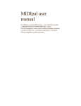
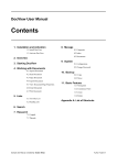
2 x 16 CHARACTER
LCD DISPLAY
GALAXY 16+ V2.7
08:58 TUE 22 NOV
1
2
3
A
4
5
6
B
7
8
9
ent
*
0
#
esc
POWER LED
Figure 1: Galaxy Mk 7 LCD Keypad.
Number Keys (0–9): are used to enter your User Code and to select and modify options.
View (A and B) Keys: are used to set the system and to step through the menu options during
programming.
Enter (ent) Key: The ent key allows you to unset the system, to access the menu options and
to accept programming selections.
Escape (esc) Key: The esc key permits you to cancel any modifications made to a menu option
and allows you to return to the previous menu option level. The esc key also aborts the setting
routine if pressed during the Exit-time from the same keypad used to initiate the setting.
Hash (#) Key: The # key is used as a toggle key, which enables or disables the programming
features of certain menu options. It is also used to select the user attributes feature in menu
option 4 – Codes.
Star (Ö) Key: The Ö key, when combined with other keys, provides special functions. The
engineer will advise of these where applicable, see also: Star (Ö) Key Features.
1
Power LED: The green power LED remains lit whenever the system is connected to the a.c.
mains power supply and a charged stand-by battery. A mains power failure is indicated by the
LED flashing slowly. A fuse or battery failure is indicated by the LED flashing quickly.
Your User Code: is a four digit personal identification number which identifies you to, and allows
you to operate, the system.
Note: Entry of an invalid code will cause the keypad to display the message INVALID CODE.
Entry of six consecutive invalid codes will cause a ten minute keypad lockout during
which the keypad horns activate and the keypad displays the message ALARM IS
ACTIVE. No further code entries will be recognised during the lockout period.
Ö) Key Features
Star (Ö
The star key is used as a shift key, when combined with other keys it provides additional
system features. To toggle the enable status of the Star key features enter either the manager
code (User 14) at the keypad and then hold down the Star (Ö) key and press the esc key; after
a second the keypad displays Ö ENABLE ON, or, Ö ENABLE OFF; release both keys.
Key Combination
Star Feature
Ö1
Ö2
Changes keypad buzzer volume.
Activates PA alarm.
Toggles On/Off to authorise Galaxy
Gold connection.
Toggles keypad backlighting On/Off.
Activates Medical alarm.
Prints the entire system details.
Prints the entire event log.
Activates the Fire alarm.
Initiates the Engineer's Test.
Indicates zone statuses.
Mgr. Code + Ö3†
Ö4
Ö5
Code + Ö6
Code + Ö7
Ö8
Ö9†
Ö#
Mgr. Code + Öent† Activates the Galaxy Gold Call Back.
Mgr. Code + Öesc Toggles Ö key featues On/Off.
†
Galaxy 16 plus only.
Table 1: Star Key Features.
Note: The Star mode must be enabled for the Star features to operate.
2
SETTING AND UNSETTING THE SYSTEM
Setting the System
Before Setting the System
Before the system is Set ensure that:
• All doors and windows are secured.
• All areas protected by movement detectors are free from obstructions and any animals
are excluded from the areas to be protected.
Full Setting the System
Enter your User Code and press the A key:
• If all the system zones are closed when the setting routine is initiated the keypad sounders
will emit a continuous tone and the keypad displays the Exit Time countdown blocks.
• If any zones are open (for example: protected doors or windows; or if someone activates
a movement detector when the setting process is started) then the keypad sounders
pulse rapidly and the keypad displays which zones are open. Closing the open zones
allows the setting routine to restart.
Leave the building using the agreed Exit Route. Close and lock the Final Exit Door and then, if
fitted, operate the Exit Terminator; the horn outputs and the keypad buzzers become silent for
four seconds, the countdown blocks all clear and the keypad buzzers emit two long tones to
confirm that the system is Set. On the keypad the message SYSTEM IS SET appears before
the display goes blank.
The setting routine can be aborted, before the system sets, by pressing the esc key on the keypad
used to initiate the setting routine.
Part Setting the System
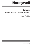
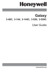
Your alarm system can be Part Set using the B key. To Part Set the system enter your User
Code then press the B key. The keypad then displays the Set/Unset status of those parts
assigned to your code, see Figure 2 Part Setting Options.
SELECT
P1=OFF
P3ÖON
Part Set options for user code
with Parts 1 and 3 assigned.
Part 1 is unset, Part 3 is set.
Figure 2: Part Setting Options.
3
The Parts marked ‘ON’ are Set, those marked ‘OFF’ are Unset. To alter the set/unset status of a
Part press the number corresponding to that part, that is, pressing the 1 key toggles the set
status of Part 1 between set/unset.
The equals sign denotes that what is displayed beside the Part number is the current status of
the Part, that is, P1=ON denotes that Part 1 is currently set. Pressing the 1 key will cause the
display to read P1TOFF, this means that Part 1 is now provisionally programmed as Unset.
The actual set status of the part will not be altered until the ent key is pressed to accept the
programming.
Once the ent key has been pressed leave the building using the agreed exit route. Close and
lock the final exit door and then operate the exit terminator; the horn outputs and the keypad
buzzers become silent for four seconds, the countdown blocks on the keypad display all clear
and the keypad buzzers emit two long tones to confirm that the system is set. On the keypad
the message SYSTEM IS SET appears before the display goes blank.
The setting routine can be aborted, before the system sets, by pressing the esc key on the
keypad used to initiate the setting routine.
Note: If the Silent Part Set facility has been enabled only the keypad display indicates the
setting status, that is, no audible tones are emitted.
Unsetting the System
Normal Entry
The system begins the unsetting routine whenever a Final door opens or an Exit/Entry zone is
activated. The keypad buzzers pulse slowly indicating that the Entry Time countdown has
started.
To unset the system, go directly to the keypad using the agreed entry route, enter your code
and press the ent key.
Note: On some systems, unsetting may alternatively be achieved, by swiping a proximity card
at the card reader.
Slow Entry
The keypad sounder begins to pulse rapidly after 75% of the entry time has expired to indicate
that time is running short. If the entry time expires before a valid user code is entered, a full
alarm occurs.
Straying From The Entry Route
If, during the entry routine, you stray from the agreed entry route and activate a zone in a protected
area an audible alarm occurs.
4
Alarm Abort
Note: If the system is programmed for Alarm Abort a period of 90 seconds after expiry of the
Entry Time is provided to enable the user to cancel an alarm caused by exceeding the
Entry Time or deviating from the entry route.
If the 90 second Alarm Abort time is exceeded then a full alarm may result in the Police
being called to the premises and the system requiring an Engineer Reset.
The installation engineer will explain the operation of the Alarm Abort function where necessary.
Cancelling Alarms
To cancel an alarm enter your user code. The keypad displays the zones that have been
activated during the alarm. Press the esc key to return to the normal display.
Certain types of alarms, once cancelled, require a code authorised with the appropriate reset
authorisation to be entered. The system prompts for a valid reset code by displaying
INTRUDER RESET REQUIRED, PA RESET REQUIRED or ENGINEER RESET REQUIRED on
the keypad.
Engineer Reset
Certain types of alarm require an engineer to visit the site and, after investigation, reset the
system.
5
6
USER MENU
For access to the menu options enter your user code then press the ent key. The keypad then
displays the menu options available to the user.
Menu Option
No
Option
01
Omit
02
Chime
03
Walk
04
C odes
05
Test
09
Log
10
Time
Table 2: Menu Options.
The user menu offers a selection of up to seven options. All users have access to the Chime
and Walk options. The Omit and Codes options are assigned to users, (if required) by the
installer.
The system manager (User 14) can also:
• test outputs (Bells and Strobe only)
• view the Event Log
• modify the Time options.
Note: The keypad returns to the normal display if no key press occurs for two minutes while
accessing the menu.
The menu options are described in the following pages.
Option 1 – Omit
This option allows authorised users to omit engineer enabled zones from the system. Once a
zone has been omitted it is not able to generate an alarm condition. Omitted zones are reinstated automatically the next time the system is unset or manually when the Omit feature is
disabled by the user.
Selecting the Omit Option
Enter your user code and press the ent key to select the menu options. Press the ent key again
to select Omit.
7
Omitting Zones
When the Omit option is selected, zone 01 is displayed, along with it’s omit eligibility and
status (NON OMITTABLE – the zone cannot be omitted; #,xx OMIT – the zone is omittable
(where xx is the zone number); OMIT – the zone is currently omitted).
If the zone is currently omitted then the box on the top line of the display is filled; if zone is not
currently omitted then the box is empty.
If the zone can be omitted and the omit status is to be changed, press the # key. The display
indicates the new omit status of the zone. Use the A or B keys to view and select other zones.
Setting with Omitted Zones
Once the required zones have been selected for omission press the ent key. The system begins
to set with the selected zones omitted, the keypad display indicates how many zones have
been omitted. The zones remain omitted until the system is unset.
To save the omit status of the zones press the esc key. The selected zones remain omitted
allowing the system to be set, with the zones omitted, at a later time. The zones remain omitted
until the next time the system is unset or the zones are manually unomitted.
Option 2 – Chime
This option allows the user to assign the Chime function to the zones on the system. Any zone
with the Chime function enabled momentarily activates the keypad buzzers each time the zone
is opened.
Selecting the Chime Option
Enter your User Code and press the 2 key.
On selecting the Chime option the first zone is displayed along with its chime status (enabled
or disabled). Pressing the # key changes the chime status of the zone.
Press the A or B keys to view and program the other zones on the system.
Press the ent key to accept the programming or esc to cancel.
Option 3 – Walk
The Walk option allows the user to Walk test the zones on the system ensuring that they are
operating correctly.
Selecting the Walk Option
Enter your User Code and press the 3 key.
8
On selecting the Walk option zone 01 is displayed. If the zone is to be tested press the # key.
Use the A or B keys to scroll through the zones on the system, each one may be selected for
inclusion in the test. When all the required zones have been selected press the ent key to start
the Walk Test.
The keypad displays the number of Walk Test zones currently open on the system. Pressing
the A or B keys allows the currently open zones to be viewed.
Walk test the selected zones by activating the appropriate sensor (movement detector, door
switch, etc). When the Walk Test is complete return to the keypad. The display shows the
number of test zones that are currently open. Press the # key to toggle the keypad display
between showing the number of test zones currently open and the number of zones registered
as tested.
To terminate the Walk Test press the esc key.
Note: If the esc key is not pressed the Walk Test remains active for 20 minutes after the last
key press.
Option 4 – Codes
The Codes option enables authorised users to allocate, modify and delete the 14 user codes
(PINs) on the system, as well as assign and modify user attributes. Only users with the Modify
Codes attribute enabled can carry out these functions.
Selecting the Codes option
Enter your User Code and press the 4 key.
Assigning Modifying and Deleting User Codes
Once the Codes option is selected the user code assignment of User 1 is displayed. If the box
next to CODE is filled then a PIN has been assigned, if it is blank then no PIN has been as-
User Number
Option Selections
01=USR 1 CODE z
ENT, 01-14=SELECT
User Code
Assigned Indicator
signed.
Figure 3: Menu Option 4 – Codes.
Use the A or B keys to select a user number and press the ent key.
To assign or modify a user PIN enter a four digit number. Press the Ö key to erase any digits
incorrectly entered. When the required four digit code is displayed press the ent key.
If a User Code is to be deleted press the Ö key four times followed by the ent key.
9
Note: User Code 13 may be assigned as a Duress Code. Entry of this code causes a Duress
alarm which will activate the PA outputs and trigger the Remote signalling Device (if
fitted); the Horn, Bells and Strobe outputs do not activate. The installation engineer will
advise you on the operation of this function where applicable.
Assigning User Attributes
No
Attribute
Description
01
S e t A cce ss
Enables the user to Set the system using the A key.
02
Unset Access
Enables the user to Unset the system using the ent key.
03
Part 1 Access
Gives the user access to Part 1.
04
Part 2 Access
Gives the user access to Part 2.
05
Part 3 Access
Gives the user access to Part 3.
06
Omitting
Enables user to omit omittable zones.
07
Modify codes
Enables user to program User Codes and attributes.
Table 3: User Code Attributes.
When the Codes option is selected User 01 is displayed. Press the ent key to select this user
or the A or B key to view the other users. To modify the attributes of the selected user press
the # key.
The Set Access attribute is displayed along with its status. Press the # key to toggle the
enable status of the attribute. An attribute is enabled when the square next to the attribute
number is black and Enable appears on the bottom line of the display.
When the required attributes have been assigned to the user, press the ent key to save the
selection or esc to cancel the programming. The display returns to the selected user number.
Press the A or B key to view and select other users.
To exit from the codes option press the esc key.
Keyswitch Zones and User Codes
Keyswitches are assigned the attributes of User Code 1, 2 or 3. A Keyswitch zone assigned to
one of these codes can Set and Unset the parts assigned to the code and reset authorised
alarms. The user code assigned to the Keyswitch must be assigned Set Access to allow the
Keyswitch to set the allocated parts The Keyswitch assumes the assigned attributes even if
the code has not been allocated a PIN.
The installation engineer will advise you of the use of keyswitch zones where necessary.
10
Option 5 – Test
The Test option allows the Manager Code (User 14) to test the Bell and Strobe outputs on the
system.
Selecting the Test Option
Enter the Manager Code and press the 5 key.
Operation of the Test Option
On selecting the Test option 5 BELLS is displayed. If the bells are to be tested press the #
key. Any output programmed as Bells will activate. To end the test repress the # key.
Pressing the A key will display 6 STROBE. If the strobes are to be tested press the # key. To
end the test repress the # key.
To exit from the Test option press the esc key.
Option 9 – Log
The Log option permits the system manager (User 14) to view the events stored in the system log.
Selecting the Log Option
Enter the Manager Code and press the 9 key.
The Event Log
Once the Log option has been selected the current date is displayed. To view the Event Log
press the A key to advance through the log or the B key to move backwards through the log.
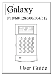
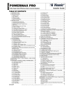
Figure 4 shows the Event Log display.
Event time
Event type
Event activation/
deactivation signaler
09:57 STAR KEY+
Ö ENABLE 092
Event number
Event descriptor
Figure 4: Viewing the Event Log.
The log event displays the event type, time, descriptor and number. Also displayed is the
activation (+) and deactivation (–) signaller.
To display the date of the event currently being displayed press the # key. Pressing the # key
again returns the display to the event details.
11
To quickly move through the log enter a three digit number between 001 and 250 followed by
the # key. The system will jump to the event number entered.
To exit from the Log option press the esc key.
Option 10 – Time
The Time option allows the system manager (User 14) to modify the four time features of the
system, these are:
•
•
•
•
Time (hr:min)
Date (dd/mm/yy)
Start Summer (dd/mm) – the date that summer time begins (clocks go forwards).
End Summer (dd/mm) – the date that summer time ends (clocks go backwards).
Selecting the Time Option
Enter your User Code and press the ent key. Press the B key until the Time option is displayed
then press the ent key.
Operation of the Time Option
On selecting the Time option 1=TIME is displayed. If the time requires to be modified press the
ent key and enter the time (this is a four digit number and must be a valid time between 00:00
and 23:59). Press the ent key to accept the programming and esc to cancel.
To change one of the other time features use the A or B keys to select the required option and
follow the same procedure as for modifying the Time option.
To exit from the Time option press the esc key.
12
APPENDIX A — ALARM AND HELP MESSAGES
ALARM IS ACTIVE: The system is currently in alarm and must be cancelled by a valid user
code.
PA RESET REQUIRED: The user code that cancelled the PA alarm does not have the authorisation to reset the system. A user code with the PA Reset attribute enabled must be entered.
The PA switch which created the alarm may also have to be reset.
ENGINEER RESET REQUIRED: This message is displayed when a tamper alarm occurs.
Tamper alarms usually require an engineer to visit the site and check all modules on the system.
INTRUDER RESET REQUIRED: The user code that cancelled the alarm does not have the
authorisation to reset the system. A user code with the PA Reset attribute enabled must be
entered. The PA switch which created the alarm may also have to be reset.
CALL ALARM CO / QUOTE NUMBER XXXXX: This message is displayed on a system with
the Technistore reset facility enabled after an alarm has been cancelled. The alarm company
should be informed that Technistore reset is required (quoting the number on the keypad
display).
INVALID CODE: The code that was entered is not registered in the system memory.
DUPLICATED CODE: When assigning new user codes, the code entered has already been
assigned to a code.
TIMED TIMEOUT DISABLED: When setting the system, the exit time has been set to infinity
and a Final zone or Push-to-Set zone is used to act as the exit terminator.
TELECOM FAILURE: A fault has occurred with the telephone line or remote signalling which
will require engineer attention.
STU LINE FAIL: A fault has occurred with the telephone line or remote signalling which will
require engineer attention.
13
14
APPENDIX B — AVOIDING FALSE ALARMS
False alarms are inconvenient and may give rise to Police response being withdrawn from your
site which may affect your insurance cover.
Here are twelve points to help you avoid false alarms:
1. Ensure that you understand how to operate the alarm system. In your absence the system
should be operated by someone thoroughly instructed in its use.
2. Ensure that:
• you know your User Code
• your Password is readily available if you need to quote it to the Alarm Receiving
Centre.
3. Before leaving the premises ensure that all doors and windows are securely closed.
4. Ensure that detection devises such as Infra-red beams or movement detectors are not
obstructed by stock or building partitions.
5. Where Passive Infra-red (PIR) or movement detectors are installed make sure that the area
is kept free from animals and birds. Particular attention should be paid to swinging signs,
fluorescent lights and Christmas decorations. Electric fans, heating or ventilation systems
should, where possible, be switched off before the system is Set.
6. Always follow the setting and unsetting procedure and keep to the entry and exit routes
agreed with the installation engineer.
7. Treat the alarm system with care and ensure that it is not accidentally damaged.
8. Consult your installer about alterations to your building and its contents if you think they
may affect your system or its performance.
9. Always report any obvious reasons for unwanted or false alarms to your installer. If
necessary an engineer will be sent to check the system where it is established that a
technical fault exists.
10. If opening or closing times are monitored by the Alarm Receiving Centre be sure you
notify them of any changes from the agreed times using your password where necessary.
11. While the system should be provided with a stand-by battery for use in the event of an a.c.
mains failure every effort should be made to restore the a.c. mains supply as soon as
possible.
12. Make sure that regular maintenance checks are carried on the system to minimise the risk
of technically related false alarms.
15
16
APPENDIX C — CONFORMITY AND STANDARDS
Compliance
The Galaxy 16 and 16 plus is compatible with the relevant parts of the following standards:
•
•
•
•
•
BS 4737
EN 60950
CTR 21
CE Standards (EN 50130-4)
EN41003
Telecoms
The equipment has been approved to {Council Decision 98/482/EC} for Pan -European single
terminal connection to the Public Switched Telephone Network (PSTN). However due to
differences between the individual PSTNs provided in different countries the approval does
not, of itself, give an unconditional assurance of successful operation on every PSTN network
termination point.
In the event of problems contact the equipment supplier in the first instance.
The Galaxy 16 and 16 plus is designed to interwork with the following networks:
Austria
France
Italy
Norway
Switzerland
Belgium
Greece
Liechtenstein
Portugal
United Kingdom
Denmark
Iceland
Luxembourg
Spain
* Germany
Finland
Ireland
The Netherlands
Sweden
Note: Contact the equipment supplier before using the Galaxy 16 and 16 plus on any network
not listed.
* May have interworking difficulties
17
18
ZONE REFERENCE TABLE
N o.
Type
Location
01
02
03
04
05
06
07
08
09
10
11
12
13
14
15
16
19
Omittable
Part
IU1-0016 (Rev 2)
20