1
Freescale Semiconductor, Inc.
Applic
AN2320/D
Rev. 0.1, 8/2002
Freescale Semiconductor, Inc...
Interfacing the MCF5272 to a
Standalone CAN Controller
Lynne Kelly
TECD Applications
The Controller Area Network (CAN) protocol is a serial communications protocol developed
in the early 1980’s by Robert Bosch GmbH for the automotive sector and is currently the in
vehicle Local Area Network (LAN) standard in Europe. The main CAN attributes are low
cost, real-time capability, and the ability to function in harsh electrical environments with a
high degree of reliability and safety (making it suitable not only for automotive applications
but other cost sensitive, safety critical, real-time applications such as industrial control,
building control, building automation, embedded networks, and medical equipment).
The ColdFire® microprocessor is an established cost-sensitive solution for industrial and
embedded network applications today. Interfacing the MCF5272 ColdFire processor to a
standalone CAN controller, with the intention of integrating CAN on a later ColdFire
derivative with embedded Ethernet, will provide a solution for an increasing number of
industrial applications requiring not only field bus communication peripherals but Ethernet
connectivity also. These applications use a field bus to carry time-critical routine data between
a central system controller and remote units such as motion controllers and sensors and require
an Ethernet link to transfer data which is processed in larger blocks on an irregular basis.
The Ethernet link facilitates the communication with standard PCs, typically running email,
database applications, and web browsers. At the extreme, internet capability would potentially
allow plants to be monitored from anywhere on the globe. For the real-time requirements at
the field bus layer, CAN would be required. Ethernet is probabilistic in that it is often uncertain
when a device on the network will be able to communicate as there is typically no guarantee
of message transfer and no prioritisation. CAN is more deterministic and hence more reliable
for the cyclical and routine transfer of data at the interface to units that require reliable and
timely control (such as motors, robotics, and PLCs).
This application note details the hardware design and software development of a reference
design which interfaces the MCF5272 microprocessor to the Infineon 82C900 standalone
CAN controller. It is recognised that an integrated solution would undoubtedly be more cost
effective, would make the design of PCBs simpler, would result in smaller space requirements,
and could reduce the CPU loading by half. However, the majority of today’s 32-bit integrated
products are focussed on automotive markets and none offer both embedded Ethernet and
CAN. This two-chip ColdFire solution is intended to provide a migration path to the first
ColdFire product with on-chip CAN and the first 32-bit microprocessor with both on-chip
CAN and on-chip Ethernet. Standalone CAN controllers still tend to ship in large numbers
which helps drive the cost of the device down. This, coupled with the low cost/performance
ratio of ColdFire microprocessors in general, makes the two-chip solution a viable alternative
in the interim.
© Freescale Semiconductor, Inc., 2004. All rights reserved.
For More Information On This Product,
Go to: www.freescale.com
MCF5272 Microprocessor
Freescale Semiconductor, Inc.
The reference design is based on the M5272C3 development board using a daughter card to provide the
standalone CAN controller circuitry. This application note details the design process, starting with an
overview of the MCF5272 processor and the 82C900 CAN controller, and the reasons for choosing them.
It is followed by a more detailed look at both the hardware design and software development. Full
schematics and basic example application software can be downloaded from the M5272C3 CAN webpage
on Freescale’s ColdFire website.Freescale websites referred to in this document can be accessed from
www.Freescale.com/semiconductors.
Freescale Semiconductor, Inc...
1.0 Design Overview
The object of this section is to outline the principles of the MCF5272 CAN reference design, to give an
overview of the MCF5272 microprocessor and the 82C900 CAN controller, and to explain the reasons for
choosing them for this design. For additional and more detailed information on the MCF5272 and the
82C900 themselves, please refer to the MCF5272 webpage, and the 82C900 user’s manual,
http://www.infineon.com/cgi/ecrm.dll/ecrm/scripts/public_download.jsp?oid=16123&parent_oid=16899.
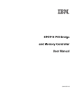
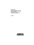
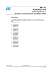
Figure 1 shows the basics of the reference design. The MCF5272 microprocessor is interfaced to the
Infineon 82C900 CAN controller using a Queued Serial Peripheral Interface (QSPI). The CAN controller
implements the CAN protocol while an external CAN transceiver, the Philips PCA82C250, provides
physical connection to the CAN bus. Two transceivers are shown here, as the Infineon CAN controller is a
twin CAN device with dual CAN nodes allowing connection to two independent CAN buses. There is no
need for a second transceiver if only one node is required.
Infineon
CAN Controller
82C900
ColdFire
MCF5272
QSPI_Clk
QSPI_CSn
QSPI_Din
QSPI_Dout
SCLK
SLS
MRST
MTSR
Tx Rx
Tx
Philips
CAN
Transceiver
PCA82C250
CAN Bus A
Rx
Philips
CAN
Transceiver
PCA82C250
CAN Bus B
Figure 1. MCF5272 CAN Reference Design Overview
1.1
MCF5272 Microprocessor
The MCF5272 is a 32-bit embedded processor based on a V2 ColdFire core. This is the most
application-specific ColdFire processor to date, targeted at the low-end communications market. On-chip
peripherals include a Fast Ethernet Controller, a USB 1.1 slave device, a Physical Layer Interface Channel
Interfacing the MCF5272 to a Standalone CAN Controller
For More Information On This Product,
Go to: www.freescale.com
Freescale Semiconductor, Inc.
CAN Controller
with four TDM ports, a software HDLC module, a QSPI module, and support for a 3 channel PWM. In
addition, it retains the System Integration Module, the Chip-Select Module, the MAC and hardware divide
unit, the General Purpose Timers, and the real-time BDM interface standard on all ColdFire devices.
The decision to use the MCF5272 ColdFire microprocessor was based on the peripheral set, ease of
interface, and the overall system cost. There is an increasing demand for Ethernet and CAN integrated on
chip; while no ColdFire product will offer both until 2003, the MCF5272 does have on-chip Ethernet, which
reduces the additional peripherals required. There are also other MCF5272-specific peripherals, including
USB and QSPI, which may be required in industrial markets.
Freescale Semiconductor, Inc...
Also, the majority of available standalone controllers offer a multiplexed bus interface and a serial
peripheral interface (SPI); they rarely offer a non-multiplexed parallel bus interface that can be gluelessly
interfaced to a ColdFire processor. Using the MCF5272 with on-chip SPI increases the choices of suitable
CAN controllers on the market and avoids increasing the complexity and cost of the design using bus
interface glue logic.
Lastly, CAN applications, both industrial and automotive, are often cost critical; therefore, it is imperative
that overall system cost is kept to a minimum. For applications requiring both CAN and Ethernet, this
solution will still be competitively priced because of the aggressive price/performance ratio of MCF5272.
A standalone CAN solution may cost more than some 32-bit integrated solutions, but these solutions are
typically targeted at different markets and offer no Ethernet connectivity.
1.2
CAN Controller
The Infineon 82C900 TwinCAN controller is a standalone CAN controller with dual CAN nodes allowing
connection to two independent buses. It can be interfaced to a host controller using either a multiplexed bus
interface or an SPI interface, or it can be interfaced to an EEPROM via the SPI interface for initialisation
when no external host is required. The 82C900 supports up to 32 message objects which can be assigned to
both CAN nodes or one CAN node. It has a built-in, scalable FIFO mechanism for message reception and
transmission and a built-in gateway functionality for transferring messages between the nodes. There is also
a timestamp/frame counter to indicate when a message was last transmitted or received (or to indicate how
many times a message has been transmitted or received) and a CAN Analyser for monitoring activity on the
CAN bus.
There are a number of standalone CAN controller modules on the market that adhere to different
specifications, support variable data rates, and require different levels of CPU intervention. The Infineon
82C900 standalone controller was chosen because it supports the CAN 2.0B protocol, because it provides
an SPI interface for glueless connection to the MCF5272, because it will support data rates up to 1Mbit/s,
and because of the level of message transmission and acceptance filtering it supports.
There are currently three CAN protocols, CAN 2.0A, CAN 2.0B, and CAN 2.0B passive. The Infineon
device supports CAN 2.0B. The difference between these protocols lies in the length of message identifier
they can transmit and receive in a message frame. A CAN 2.0A controller can handle standard frames with
an 11-bit identifier while a CAN 2.0B controller can transmit standard frames and extended frames with
29-bit identifiers. Finally, CAN 2.0B passive controllers can transmit only standard frames but can receive
both standard and extended frames. For the majority of today’s applications CAN 2.0B is considered
standard, with system designers often requiring the extended 29-bit identifier to relieve them from
compromises with respect to defining well-structured naming schemes. The majority, if not all, of the
integrated CAN solutions on the market support CAN 2.0B. The backward-compatible nature of the CAN
protocol ensures the Infineon device can also handle messages with the standard frame format.
Interfacing the MCF5272 to a Standalone CAN Controller
For More Information On This Product,
Go to: www.freescale.com
CAN Transceiver
Freescale Semiconductor, Inc.
Regarding the interface, this has been touched on before. Few standalone CAN controllers on the market
today have non-multiplexed bus interfaces and none offer a glueless interface to the MCF5272 external bus.
Design complexity and additional cost in using a parallel interface resulted in SPI being the preferred
choice.
Freescale Semiconductor, Inc...
In terms of data rate support, CAN data rates can vary between 10kbit/s and 1Mbit/s, depending on the
length of the bus line and on the degree of fault tolerance required. A bus length of less than 40m makes
1Mbit/s achievable. CAN controllers vary in the data rates they support; most support up to 0.5Mbit/s or
1Mbit/s. The Infineon controller can handle 1Mbit/s which is desirable for many of today’s real-time
industrial applications.
Finally, standalone CAN controllers vary in the extent to which the CPU is required to take over message
transmission. The simplest controller, known formerly as BasicCAN, has hardware logic dedicated to
creating and verifying the bitstream according to protocol. Administration of data sets to be sent and
received and comprehensive acceptance filtering is carried out by the CPU, placing increased overhead on
the processor. Full CAN controllers, like the Infineon 82C900, include extra logic to provide object storage,
support additional prioritisation capabilities, and implement comprehensive acceptance filtering. This,
along with the additional on-chip FIFO and gateway mechanisms, ensures CPU overhead is kept to a
minimum. In the end, this means real-time performance is optimised, which is often the most important
criteria in the types of industrial-control and automation applications for which this is intended.
1.3
CAN Transceiver
The Philips PCA82C250 high-speed transceiver was chosen as the interface between the CAN controller
and the CAN physical bus because it supports data rates up to a maximum of 1Mbps. Alternate transceivers
such as fault-tolerant and single-wire transceivers limit the maximum data rate to 125 kbit/s and 33.33
kbit/s, respectively. High-speed transceivers typically support data rates in excess of 500 kbit/s.
2.0 Hardware Design
The MCF5272 CAN reference design is developed around the M5272C3 evaluation board using a daughter
card for the CAN circuitry. The daughter card connects to the evaluation board using expansion connectors
already provided.
The M5272C3 board provides the 10/100 Ethernet interface, RS232 interface, BDM interface, 4MB
SDRAM, and 2MB Flash ROM for system development. For additional detailed information on the
evaluation board, including full schematics, refer to the M5272C3 user’s manual on the M5272C3 CAN
webpage.
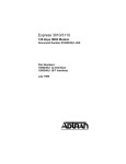
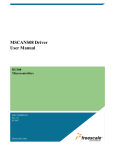
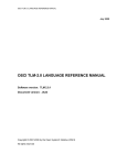
Figure 2 outlines the hardware design of the CAN daughtercard. The main features and key issues
(interface, reset, clocking, power supply, and more) are explained in the remainder of this section. Full
schematics and schematic summary can be downloaded from the ColdFire website.
Interfacing the MCF5272 to a Standalone CAN Controller
For More Information On This Product,
Go to: www.freescale.com
+3.3V
SPI Interface
-INT3
-INT1
QSPI_DIN
QSPI_DOUT
QSPI_CLK
QSPI_CS0
-RST0
Freescale Semiconductor, Inc.
GND
+5V
MAX682
ACT1100
Charge Pump
24MHz Clock
82C900
Freescale Semiconductor, Inc...
CAN Controller
PCA82C250
CAN Transceiver
PCA82C250
P[0..7]
CAN Transceiver
CANH
CANL
Figure 2. CAN Daughter-Card Circuitry
2.1
SPI Interface
The MCF5272 QSPI module provides a glueless SPI interface to the 82C900’s synchronous serial channel
(SSC). The QSPI and SSC hardware interfaces are detailed here.
2.1.1
MCF5272 QSPI Module
The QSPI module on the MCF5272 provides a serial peripheral interface with queued transfer capability,
which allows up to 16 data transfers with no CPU intervention. The QSPI interface will support data
transfers, msb first, of anywhere between 8 and 16 bits. It will support baud rates from 129.4Kbps up to 16
MBps and can be interfaced to a maximum of 15 devices using the four peripheral chip-select lines.
The module has a total of seven signals: QSPI_Dout, which is the serial data output from the QSPI module,
QSPI_Din, which is the serial data input to the QSPI module, QSPI_CLK, which is the QSPI clock output,
and QSPI_CS[0:3], which are the four peripheral chip-select output signals. Four signals are used to
interface to the 82C900: QSPI_Dout, QSPI_Din, QSPI_CLK and QSPI_CS0.
The clock phase, clock polarity, chip select active logic level, and delays before and after transfer
highlighted in Figure 3 are all programmable via the QSPI registers. This flexibility in clocking and data
transfer eliminates the need for additional glue logic to meet the 82C900 timing requirements or to
accommodate the polarity and phase of its clock, which are internally configured. The data transfer baud
rate is also programmable; this is explained in more detail in Section 2.2, “Clocking.”
Interfacing the MCF5272 to a Standalone CAN Controller
For More Information On This Product,
Go to: www.freescale.com
Freescale Semiconductor, Inc...
SPI Interface
Freescale Semiconductor, Inc.
A = QSPI clock delay. Determines the length of delay from the assertion of the chip-select to a valid
QSPI_CLK delay. Programmed in the QSPI delay register (QDLYR).
B = Delay after transfer. Determines the length of delay after a serial transfer. Programmed in the QSPI
delay register (QDLYR).
Clock polarity is set to 0 making the inactive state of QSPI_CLK to be logic level 0.
Clock phase is set to 1 to have data changed on the leading edge and captured on the following edge.
Figure 3. QSPI Clocking and Data Transfer Parameters
2.1.2
82C900 Synchronous Serial Channel
The 82C900 Synchronous Serial Channel (SSC) is an SPI-compatible serial interface, which can be used to
connect the CAN controller to an external host. Transfers can be single-read or single -write accesses
although the channel itself is optimised for multiple transfers to consecutive addresses. An example of a
consecutive read access and a consecutive write access is shown in Figure 4. When the chip select is
activated, the first byte transferred should always be an address byte. The address itself is 7 bits wide with
the 8th bit, A7, used to indicate whether the access is a read or a write. If a consecutive access is requested,
then all transfers following the address are data transfers. The SSC internally increments the register
addresses during the transfer. The chip-select signal must remain active for the duration.
The 82C900 SSC is configured internally for 8-bit data transfers with msb first. Clock polarity is set to
inactive high; clock phase is configured for data shift on the leading edge and data capture on the following
edge of the SPI clock. The MCF5272 is also fixed for msb-first transfer while the data transfer size, the clock
polarity, and clock phase are programmable as detailed in Section 2.1.1, “MCF5272 QSPI Module.”
Mode pins on the 82C900 are used to configure the interface, to choose between an 8-bit multiplexed bus
and the SSC, and to select master when no external host is used or slave when it is. In this design, the
MCF5272 is the external host acting as master in the system, and the mode input pins are set for the SSC
interface and slave operation.
The MCF5272 QSPI signals are connected to four control pins on the 82C900, the functions of which are
multiplexed by the mode inputs. When the SSC interface is used in slave mode, control pin 0 (the 82C900
chip-select) is configured as an input, control pin 1 is configured as a serial clock input, control pin 2 is
configured as a serial data input (Master Transmit Slave Receive), and control pin 3 is configured as a serial
data output (Master Receive Slave Transmit).
Interfacing the MCF5272 to a Standalone CAN Controller
For More Information On This Product,
Go to: www.freescale.com
Freescale Semiconductor, Inc.
SPI Interface
Infineon has added an optional fifth signal, a ready signal (RDY), to the standard SPI interface. This is a
handshake signal, which can be used to indicate when the serial interface can be accessed by the host.
However this RDY signal is not required provided the SSC timings detailed in Section 2.1.3, “Timing” are
adhered to. While it would be a simple case of connecting the ready input signal to a GPIO pin on the
MCF5272 and reading the level before accessing the CAN controller, the MCF5272 QSPI programmable
delays before and after transfer means the timing specifications can be met without using the RDY signal.
Freescale Semiconductor, Inc...
2.1.3
Timing
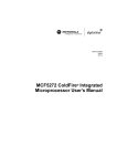
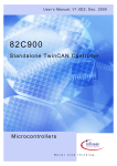
Figure 4 gives the 82C900 SSC timing requirements that must be met in the absence of a ready signal that
indicates to the host when a transfer is allowed. A consecutive-read access and a consecutive-write access
are shown. The first byte transferred is the address and any subsequent transfers are data bytes which are
read or written to consecutive addresses starting at the address defined. In this mode, the chip-select signal
must remain active until the transfer of all data for that access is complete.
All timing requirements, except minimum delay after reset (see Section 2.3, “Reset”), are met by
programming the QSPI clock delay and the QSPI delay after transfer on the MCF5272. The QSPI clock
delay determines the delay between chip-select assertion and the first valid serial clock transition, and the
QSPI delay after transfer determines the delay after each serial transfer. In Figure 4, the clock delay is
programmed to meet specification (A), while the delay after transfer is programmed to meet all other timing
requirements. The delay after transfer is inserted not only on the negation of the chip-select signal (E) but
also between data transfers (B, C, F and G) and following the final data transfer (D) of consecutive reads or
writes.
The QSPI clock delay (SCLKDELAY) and the delay after transfer (TxRxDELAY) are defined by the following
equations:
QCD
SCLK DELAY = ------------------CLKIN
32 × DTL
TxRx DELAY = -----------------------CLKIN
QCD has a range of 1-127, DTL has a range of 1-255 and CLKIN is the system clock frequency.
For a 66MHz system clock, the QSPI clock delay is programmable between 15ns and 1.9µs, and the delay
after transfer is programmable between 485ns and 124µs (with the option of using a standard delay of
258ns). A QCD of 6 (90ns delay) and a DTL of 2 (970ns) were chosen to meet the worst case specifications
shown in Figure 4.
Interfacing the MCF5272 to a Standalone CAN Controller
For More Information On This Product,
Go to: www.freescale.com
Freescale Semiconductor, Inc.
Clocking
Read
Access
READ
ACCESS
Serial Clk
Data In
8 CLKS
8 CLKS
8 CLKS
Write
WRITEAccess
ACCESS
8 CLKS
Addr
Data Out
Data
Data
8 CLKS
8 CLKS
8 CLKS
Addr
Data
Data
Data
CS
Freescale Semiconductor, Inc...
A
B
C
Name
D
E
F
A
Parameter
G
Min Time, fCAN = 24 MHz
A
CS active to SerialClk active
84ns
B
Address transfer to data byte transfer, read access
584ns
C
Data byte transfer to data byte transfer, read access
584ns
D
Last data byte transfer to CS inactive
459ns
E
CS inactive to CS active
167ns
F
Address transfer to data byte transfer, write access
209ns
G
Data byte transfer to data byte transfer, write access
209ns
Figure 4. 82C900 SSC Timing Specification
2.2
2.2.1
Clocking
CAN Controller Clock Input
A 24-MHz external oscillator is used to clock the CAN controller. This ensures that the CAN protocol can
be handled on both nodes at 1Mbps when the CAN controller is interfaced to an external host using the
maximum access rate. This assumes the built-in gateway and FIFO functions are not being used. For
systems that require these additional data handling capabilities, a higher frequency may be required unless
the external host-access rate is reduced. In the worst case, the data handling capability would be reduced to
500kbps for each node when both the FIFO and the gateway functions are running with a 24-MHz clock
input. Using a 24-MHz clock input also means the oscillator chip can be replaced directly by the USB clock
and clock divider with no software modification or interface timing implications if preferred. The integrated
USB controller on the MCF5272 requires a 48-Mhz oscillator which is provided externally on the M5272C3
board.
2.2.2
SPI Baud Rate
f CAN
------------
The 82C900 CAN controller serial interface baud rate is limited to 4 where f CAN is the input clock
frequency. At 24 MHz this gives a maximum possible baud rate of 6 Mbps. The MCF5272 QSPI is
programmable and is set by the baud field in the QSPI mode register (QMR) as follows:
CLKIN
SPI BAUDRATE = ------------------2×B
Interfacing the MCF5272 to a Standalone CAN Controller
For More Information On This Product,
Go to: www.freescale.com
Freescale Semiconductor, Inc.
Reset
where CLKIN is the system clock frequency (66 MHz here) and B represents the value in the baud field of
the QMR register and lies between 1 and 255. As a baud rate of 6MBps would require B = 5.5 the maximum
achievable baud rate will be 5.5 MBps, with B = 6.
2.3
Reset
Freescale Semiconductor, Inc...
The reset output signal from the MCF5272 processor (-RSTO) is used to drive the reset of the 82C900 CAN
controller. As the reset signal to the CAN controller need only be asserted for 5 CAN clock cycles which at
24 MHz equates to 14 MCF5272 CPU clocks when running at 66 MHz, any MCF5272 reset will reset the
CAN controller.
The four MCF5272 resets are master reset, normal reset, soft reset, and software watchdog timer reset.
Master reset will reset the entire processor including SDRAM, normal reset will terminate all bus activity
except SDRAM refresh cycles ensuring data stored in SDRAM is not lost during a reset, soft reset will reset
all external devices and all internal peripherals excluding the SIM, the chip-select controller, the interrupt
controller, the GPIO module and the SDRAM controller, and the software watchdog timer will generate a
reset if it is not periodically accessed by software as programmed. -RSTO is driven low for 128 CPU clocks
during soft reset and for 32K CPU clocks when a low input level is applied to -RSTI during a master and
normal reset or when the software watchdog timer times out.
It should be noted that there must be a delay of 1100 CAN clock cycles following the negation of -RSTO
and before accessing the CAN controller. Reset exception processing which follows the negation of -RSTO
will not provide the required delay but the system initialisation process should.
2.4
Power
The M5272C3 board which the CAN daughter card is connected to supplies 3.3V power only. The 5V input
required by the CAN controller, the CAN transceivers, and the 24 MHz oscillator chip is provided by a
Maxim charge pump on the daughter card itself. The MAX682 was chosen because it is capable of
delivering the 250mA required to meet the maximum possible combined load from the 82C900, the
PCA82C250, and the ACT1100 oscillator chips.
2.5
Interrupts
The 82C900 has 72 interrupt request sources in total. These 72 sources are assigned to 1 of 8 CAN interrupt
nodes which can then be driven on the output pins OUT0 and OUT1.
The 72 interrupt sources are divided up as follows. Each of the 32 message objects have 2 interrupt request
sources indicating when a message has been received or when a message has been transmitted. Each CAN
node also has four global interrupt requests which include
•
•
•
•
TxRx OK—Indicates when a message, assigned to that node, has been transmitted or received
okay
Last Error Code—Indicates the last error to occur (stuff/format/CRC/bus arbitration)
Error—Indicates when the number of CAN bus errors exceeds a predefined limit
Frame Counter—Indicates transfer sequence of message objects and the time instant a frame was
last transmitted or received.
Each message object assigned to the CAN node can be a source for these errors. Mask registers are used to
determine which interrupts within each message should be recognised or ignored for the generation of the
CAN node global interrupt request.
Interfacing the MCF5272 to a Standalone CAN Controller
For More Information On This Product,
Go to: www.freescale.com
82C900 Extended I/O
Freescale Semiconductor, Inc.
Both the message-specific and the CAN node specific global interrupts are distributed among eight interrupt
nodes, CAN interrupt nodes 0 – 7, via Message Configuration and Global Interrupt Node Pointer registers.
Each node can then be assigned to one of the two interrupt request outputs, OUT0 and OUT1. Requests
received from interrupt node 1 only or from interrupt nodes 1, 3, 5 and 7 combined can be output on OUT1,
and requests from interrupt node 0 only or from nodes 0, 2, 4, 6 again combined, can be output on OUT0.
It should be noted that OUT0 has dual functionality. The 82C900 has an on-chip oscillator that can be used
to generate a system clock. With an on-chip clock divider, OUT0 can be used to provide a reduced-clock
output for external devices which may need a slower clock. OUT0 is configurable via the Global Device
Control Register.
Freescale Semiconductor, Inc...
2.6
82C900 Extended I/O
When using the SSC on the 82C900, the I/O pins of the parallel bus (P0:P7) can be configured as I/O with
extended functionality. The logic state of each pin is recorded in registers on the CAN device which can be
accessed by the CAN bus. They can be used
•
To initiate a message transfer
•
As GPIO where the pin state is written to or read from the CAN device registers
•
As a CAN status monitor to monitor the internal status of the CAN controller during message
transfer including which part of a data/remote/error frame is currently being transferred and which
value has been read by a CAN node (A,B) on the associated bus. There are also output clock lines
which are asserted high once during each bit time.
These I/O pins are taken out to a header on the daughtercard.
3.0 Software Development
This section outlines the software for a basic application example that sets up the 82C900 CAN controller
to transmit a message, receive a message, and interrupt the MCF5272 when a message is received. It begins
with an overview of the code required to send and receive a byte over the MCF5272 QSPI, illustrating how
data is written to and read from the 82C900 registers. It is followed by a description of the 82C900 register
set and details on how the registers are addressed when using the 82C900 SSC interface. The initialisation
of both CAN nodes is then covered and finally, in Section 3.4, “CAN Transmit and Receive,” two message
objects are set up, one assigned to CAN node A for transmit and one assigned to CAN node B for receive.
The software was verified initially by connecting the CAN transceivers on the daughtercard externally. The
transmit and receive message objects assigned to each node were given the same ID so node B would receive
the message transmitted by node A and generate an interrupt. The M5272C3 board and CAN daughter card
were then connected via a CAN bus to an MPC555 development board to test the MCF5272 CAN reference
design fully.
The code has been developed using Wind River’s Diab compiler and visionClick debugger and can be
downloaded from the MCF5272C3CAN webpage for modification for another tool chain or to be used as a
template for further development.
Interfacing the MCF5272 to a Standalone CAN Controller
For More Information On This Product,
Go to: www.freescale.com
Freescale Semiconductor, Inc.
Transmitting and Receiving over the MCF5272 QSPI Interface
3.1
Transmitting and Receiving over the MCF5272
QSPI Interface
Freescale Semiconductor, Inc...
The QSPI module is a standard SPI interface with queuing capabilities. Using an 80-byte block of static
RAM, the QSPI module can queue up to 16 transfers without CPU intervention. The RAM is divided into
a receive data RAM which is the initial destination for all received data, a transmit data RAM which is a
buffer for all out-bound data, and a command RAM which holds command data for each QSPI command to
be executed (including which chip-select to activate, whether to enable delays, how many bits to transfer
etc.).
The RAM is organised as 16 entries where 1 byte of command data, 1 word of transmit data, and 1 word of
receive data comprise 1 queue entry. It cannot be accessed directly but must be accessed via the QSPI
address register (QAR) and the QSPI data register (QDR). A write to the QDR results in data being written
to the RAM entry specified by the address in the QAR and a read from the QDR results in the data stored
at the address specified by the QAR being written to the QDR. The address stored in the QAR automatically
increments after a read from or a write to the QDR.
QSPI operation is initiated by writing a queue of commands to the command RAM, writing transmit data
into transmit RAM, and then enabling the QSPI to begin transfer. The QSPI begins execution at the
command in the queue entry pointed to by a queue pointer and the transmit data at the same entry is
transmitted. Data that is simultaneously received is stored in this entry before the queue pointer is
incremented. When all commands are executed the QSPI finished flag is set and an interrupt can be
generated. Queue pointers can be used to begin or end transfer at any entry in the queue and to determine
which command was last completed.
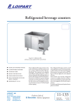
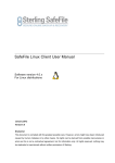
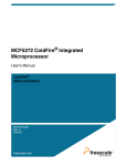
The flowchart in Figure 5 outlines the process of sending a byte of data to and reading a byte of data from
the 82C900 CAN controller. This explains the initialisation and mechanics of the MCF5272 QSPI interface
only. Accessing the registers on the Infineon device, in particular the addressing, is described in detail in
Section 3.2, “Accessing the 82C900 Register.” The initialisation, the send byte, and the receive byte
software routines are also given. Refer to the MCF5272 user’s manual on the MCF5272 webpage for the
QSPI module register set and bit level detail.
Interfacing the MCF5272 to a Standalone CAN Controller
For More Information On This Product,
Go to: www.freescale.com
Freescale Semiconductor, Inc.
FI
X
IN
W
O
R
Set QSPI
QSPI Mode
Mode Register
Register
Set
5.5 Mbit/s
Mbit/s baud
baud rate,
rate, 88 bit
bit data
data transfer
transfer
5.5
Data
change
on
leading,
capture
on following
following
Data change on leading, capture on
Clock idle
idle high
high
Clock
D
!
Transmitting and Receiving over the MCF5272 QSPI Interface
BO
XE
S
.N
EE
D
TO
Set QSPI
QSPI Delay
Delay Register
Register
Set
Delay after
after transfer
transfer == 22 == 970ns
970ns
Delay
QSPI
clock
delay
=
6
=
91ns
QSPI clock delay = 6 = 91ns
TE
XT
IN
SO
M
E
Clear QSPI
QSPI Interrupt
Interrupt Register
Register
Clear
Clear QSPI
QSPI finish,
finish, abort
abort and
and write
write collision
collision flags
flags
Clear
Clear interrupts
interrupts
Clear
R
EA
D
AN
’T
C
Freescale Semiconductor, Inc...
Point to
to Command
Command RAM
RAM
Point
Set QAR
QAR to
to 0x20
0x20 to
to point
point to
to first
first queue
queue entry
entry in
in command
command
Set
RAM
RAM
Write to
to Command
Command RAM
RAM via
via QDR
QDR
Write
bit data
data transfer
transfer
88 bit
Use
/CS0,
assert
between
transfers
Use /CS0, assert between transfers
Enable programmable
programmable clock
clock and
and transfer
transfer delays
delays
Enable
RD or
or WR?
WR?
RD
Point to
to Transmit
Transmit RAM
RAM
Point
Set QAR
QAR to
to 0x00
0x00 to
to point
point to
to first
first queue
queue entry
entry in
in command
command
Set
RAM
RAM
Point to
to Transmit
Transmit RAM
RAM
Point
Set QAR
QAR to
to 0x00
0x00 to
to point
point to
to first
first queue
queue entry
entry in
in Tx
Tx RAM
RAM
Set
Load Transmit
Transmit RAM
RAM via
via QDR
QDR
Load
Write QDR
QDR with
with address
address of
of 82C900
82C900 register
register
Write
Write QDR
QDR with
with data
data byte
byte for
for 82C900
82C900 register
register
Write
Load Transmit
Transmit RAM
RAM via
via QDR
QDR
Load
Write QDR
QDR with
with address
address of
of 82C900
82C900 register
register
Write
Write QDR
QDR with
with dummy
dummy addr
addr for
for 82C900
82C900 register
register
Write
Set QSPI
QSPI Wrap
Wrap Register
Register
Set
Set start
start queue
queue pointer
pointer to
to the
the top
top of
of transmit
transmit RAM.
RAM.
Set
Set end
end queue
queue pointer
pointer to
to 11 for
for Tx
Tx of
of 22 bytes
bytes
Set
Set chip
chip select
select inactive
inactive level
level to
to 11
Set
Enable Transfer
Transfer
Enable
Set SPE
SPE field
field in
in the
the QSPI
QSPI delay
delay register
register to
to enable
enable
Set
Enable Transfer
Transfer
Enable
Set SPE
SPE field
field in
in the
the QSPI
QSPI delay
delay register
register to
to enable
enable
Set
Poll for
for Completion
Completion
Poll
Poll the
the SPI
SPI finish
finish flag
flag in
in the
the QIR.
QIR.
Poll
Poll for
for Completion
Completion
Poll
Poll the
the SPI
SPIfinish
finish flag
flag in
in the
the QIR.
QIR.
Poll
Point to
to Receive
Receive RAM
RAM
Point
Set QAR
QAR to
to 0x10
0x10 to
to point
point to
to first
first entry
entry in
in Rx
Rx RAM.
RAM.
Set
Read Receive
Receive RAM
RAM via
via QDR
QDR
Read
Read dummy
dummy byte.
byte.
Read
Read
byte
from
82C900
register
access.
Read byte from 82C900 register access.
Figure 5. MCF5272 QSPI: Reading and Writing to the 82C900
The QSPI initialisation software in the example code is used to set up the baud rate, clock phase, clock
polarity, clock delay, and delay after transfer. It is also used here to set up the command RAM. All entries
in the command RAM have the programmable delays enabled. As the timing specifications of the 82C900
Interfacing the MCF5272 to a Standalone CAN Controller
For More Information On This Product,
Go to: www.freescale.com
Freescale Semiconductor, Inc.
Transmitting and Receiving over the MCF5272 QSPI Interface
vary between the different accesses (for example, the minimum time for a read access can be three times as
much as a write access), it may be desirable to change the command RAM entries when switching between
a read transfer and a write transfer. QSPI initialisation code:
void
mcf5272_qspi_init()
{
MCF5272_IMM *imm = mcf5272_get_immp();
/*Set QSPI mode register, 5.5Mbit/s, 8 bit, data change on leading, clock idle high*/
MCF5272_WR_QSPI_QMR(imm,MCF5272_QSPI_QMR_CAN);
/*Set delay after transfer and clock delay*/
MCF5272_WR_QSPI_QDLYR(imm,MCF5272_QSPI_QDLYR_CAN);
Freescale Semiconductor, Inc...
/*Clear flags and interrupts*/
MCF5272_WR_QSPI_QIR(imm,MCF5272_QSPI_QIR_CAN);
/*Point to top of command RAM*/
MCF5272_WR_QSPI_QAR(imm,MCF5272_QSPI_QAR_Comm);
/*Set each entry for continuous transfer, 8 bit transfer, to use /CS0 and delays*/
MCF5272_WR_QSPI_QDR(imm,MCF5272_QSPI_QDR_CR_CONT);
MCF5272_WR_QSPI_QDR(imm,MCF5272_QSPI_QDR_CR_CONT);
MCF5272_WR_QSPI_QDR(imm,MCF5272_QSPI_QDR_CR_CONT);
MCF5272_WR_QSPI_QDR(imm,MCF5272_QSPI_QDR_CR_CONT);
MCF5272_WR_QSPI_QDR(imm,MCF5272_QSPI_QDR_CR_CONT);
MCF5272_WR_QSPI_QDR(imm,MCF5272_QSPI_QDR_CR_CONT);
MCF5272_WR_QSPI_QDR(imm,MCF5272_QSPI_QDR_CR_CONT);
MCF5272_WR_QSPI_QDR(imm,MCF5272_QSPI_QDR_CR_CONT);
MCF5272_WR_QSPI_QDR(imm,MCF5272_QSPI_QDR_CR_CONT);
MCF5272_WR_QSPI_QDR(imm,MCF5272_QSPI_QDR_CR_CONT);
MCF5272_WR_QSPI_QDR(imm,MCF5272_QSPI_QDR_CR_CONT);
MCF5272_WR_QSPI_QDR(imm,MCF5272_QSPI_QDR_CR_CONT);
MCF5272_WR_QSPI_QDR(imm,MCF5272_QSPI_QDR_CR_CONT);
MCF5272_WR_QSPI_QDR(imm,MCF5272_QSPI_QDR_CR_CONT);
MCF5272_WR_QSPI_QDR(imm,MCF5272_QSPI_QDR_CR_CONT);
MCF5272_WR_QSPI_QDR(imm,MCF5272_QSPI_QDR_CR_CONT);
}
Writing to the 82C900 register:
/*The address of 82C900 register and data to be written to it are passed*/
void QSPI_SendByte(uint16 CanRegAddr, uint8 Data)
{
MCF5272_IMM *imm = mcf5272_get_immp();
/*Determine 82C900 register address*/
CAN_SetPageReg((uint8)(CanRegAddr>>7));
/*Point to top of Tx RAM*/
Interfacing the MCF5272 to a Standalone CAN Controller
For More Information On This Product,
Go to: www.freescale.com
Freescale Semiconductor, Inc.
Transmitting and Receiving over the MCF5272 QSPI Interface
MCF5272_WR_QSPI_QAR(imm, MCF5272_QSPI_QAR_Tx);
/*Write 82C900 register address into Tx RAM via QDR indicating a write*/
MCF5272_WR_QSPI_QDR(imm,(uint8)(CanRegAddr|CanWriteMask));
/*Write data for 82C900 register into Transmit RAM via QDR*/
MCF5272_WR_QSPI_QDR(imm,Data);
/*Set Wrap register for byte transfer (2 bytes), starting at top of Tx RAM*/
MCF5272_WR_QSPI_QWR(imm,MCF5272_QSPI_QWR_SendByte);
/*Set SPE flag in Delay register to enable transfer*/
MCF5272_WR_QSPI_QDLYR(imm,MCF5272_QSPI_QDLYR_CanEnable);
/*Poll the QSPI finish flag for completion*/
Freescale Semiconductor, Inc...
while (!(MCF5272_RD_QSPI_QIR(imm) & MCF5272_QSPI_QIR_QSPIFinish))
;
}
Reading an 82C900 register:
/*The address of 82C900 register to be read is passed*/
uint8 QSPI_ReadByte(uint16 CanRegAddr)
{
MCF5272_IMM *imm = mcf5272_get_immp();
/*Determine 82C900 register address*/
CAN_SetPageReg((uint8)(CanRegAddr>>7));
/*Point to top of Tx RAM*/
MCF5272_WR_QSPI_QAR(imm,MCF5272_QSPI_QAR_Tx);
/*Write 82C900 register address to be read into Tx RAM via QDR*/
MCF5272_WR_QSPI_QDR(imm,(uint8)(CanRegAddr&CanReadMask));
/*Dummy transmission to ensure QSPI clock enable for receiving byte*/
MCF5272_WR_QSPI_QDR(imm,(uint8)(CanRegAddr&CanReadMask));
/*Set Wrap register for byte read transfer (2 bytes) starting at top of Tx RAM*/
MCF5272_WR_QSPI_QWR(imm,MCF5272_QSPI_QWR_ReadByte);
/*Set SPE flag in Delay register to enable transfer*/
MCF5272_WR_QSPI_QDLYR(imm,MCF5272_QSPI_QDLYR_CanEnable);
/*Poll the QSPI finish flag for completion*/
while (!(MCF5272_RD_QSPI_QIR(imm) & MCF5272_QSPI_QIR_QSPIFinish))
;
/*Point to top of Rx RAM*/
MCF5272_WR_QSPI_QAR(imm,MCF5272_QSPI_QAR_Rx);
/*Read dummy byte received as address being transmitted*/
dummy
= (uint8)MCF5272_RD_QSPI_QDR(imm);
/*Read data received from the 82C900 register*/
RxByte = (uint8)MCF5272_RD_QSPI_QDR(imm);
}
Interfacing the MCF5272 to a Standalone CAN Controller
For More Information On This Product,
Go to: www.freescale.com
Freescale Semiconductor, Inc.
Accessing the 82C900 Register
3.2
Accessing the 82C900 Register
Freescale Semiconductor, Inc...
The 82C900 register set is divided between the global control shell and the message buffer unit. The global
control shell registers are known as the standalone shell registers, and they control the initialisation process
after power-on or reset, provide status information to the CPU on message transfers or on any pending
transfer interrupts, and are responsible for condensing the 72 interrupt sources to 8 to be distributed among
the 8 available CAN interrupt nodes. The registers assigned to the message buffer unit are known as the
TwinCAN registers. These registers are used as buffers for the 32 message objects and also as managers of
the FIFO, to transfer messages between the nodes internally if the in-built gateway logic is being used, and
to provide interrupt requests for transmission or on reception of a message object. An overview of the
memory map is given below in Figure 6. For register-specific information refer to the Infineon 82C900
user’s manual,
http://www.infineon.com/cgi/ecrm.dll/ecrm/scripts/public_download.jsp?oid=16123&parent_oid=16899.
+0000H
Standalone Registers
+0080H
Reserved
+0200H
TwinCAN Registers (CAN node & Control)
+02C0H
Reserved
+0300H
TwinCAN Registers (Message Object 0)
+0320H
TwinCAN Registers (Message Object 1)
+06E0H
TwinCAN Registers (Message Object 31)
Figure 6. 82C900 Register Map
Accessing all registers on the memory map requires 11-bit addressing. Referring to Figure 4, the first byte
transmitted by the host during an access contains address information. All other transfers during the same
access are data transfers. Of the first byte transferred, only the lower seven bits are used to define the register
address. The eighth bit, A7, is used to indicate whether the access is a read or a write transfer. The upper
four bits of the register address are provided by the PAGE register in the standalone shell register set. The
PAGE register itself can be accessed at addresses xx7CH or xxFCH and hence independently of the value
stored in the register.
The 82C900 register address is therefore split in two as illustrated by the code below. This highlights the
setting of the register address for a write access. The upper four bits of the address are written to the PAGE
register and the lower 7 bits are concatenated with the read or write command and transmitted over the SPI.
void QSPI_SendByte(uint16 CanRegAddr, uint8 Data)
{
MCF5272_IMM *imm = mcf5272_get_immp();
/*Pass upper 4 bits of 82C900 register address to be accessed */
CAN_SetPageReg((uint8)(CanRegAddr>>7));
MCF5272_WR_QSPI_QAR(imm, MCF5272_QSPI_QAR_Tx);
/*First byte to Tx over QSPI.
indicate a write operation*/
Use lower 7 bits of address and force the 8th bit to 1 to
MCF5272_WR_QSPI_QDR(imm,(uint8)(CanRegAddr|CanWriteMask));
Interfacing the MCF5272 to a Standalone CAN Controller
For More Information On This Product,
Go to: www.freescale.com
82C900 Initialisation
Freescale Semiconductor, Inc.
MCF5272_WR_QSPI_QDR(imm,Data);
MCF5272_WR_QSPI_QWR(imm,MCF5272_QSPI_QWR_SendByte);
MCF5272_WR_QSPI_QDLYR(imm,MCF5272_QSPI_QDLYR_CanEnable);
while (!(MCF5272_RD_QSPI_QIR(imm) & MCF5272_QSPI_QIR_QSPIFinish))
;
}
/*The upper 4 bits of the register address are passed.*/
void CAN_SetPageReg(uint8 PageNumber)
{
Freescale Semiconductor, Inc...
MCF5272_IMM *imm = mcf5272_get_immp();
MCF5272_WR_QSPI_QAR(imm,MCF5272_QSPI_QAR_Tx);
/*Page register address. Can be accessed regardless of its contents*/
MCF5272_WR_QSPI_QDR(imm,CAN_PAGE|CanWriteMask);
/*Write upper four bits to PAGE register and enable auto increment*/
MCF5272_WR_QSPI_QDR(imm,PageNumber|CanAutoInc);
MCF5272_WR_QSPI_QWR(imm,MCF5272_QSPI_QWR_SetPageReg);
MCF5272_WR_QSPI_QDLYR(imm,MCF5272_QSPI_QDLYR_CanEnable);
while (!(MCF5272_RD_QSPI_QIR(imm) & MCF5272_QSPI_QIR_QSPIFinish))
;
}
To optimise data transfer between the host and the 82C900, the SSC can transfer a data stream upon the
transmission of a single address. This is illustrated in Figure 4. The control bit for incrementing the address
during these consecutive-read and consecutive-write accesses is contained in the PAGE register. When set,
the contents of the address register are automatically incremented by one after each data-byte transfer.
Incrementing is stopped at the boundaries between CAN message objects to prevent unintended corruption
of CAN messages. Accidentally overwriting the PAGE register is also prevented.
3.3
82C900 Initialisation
The 82C900 initialisation software logically connects CAN nodes A and B to a CAN bus and allows them
to participate in message transfer. Initialisation is required after the controller is reset by the MCF5272
processor and after the occurrence of a ‘bus off’ event, both of which will logically disconnect a node from
its associated bus.
The code used to configure the CAN nodes is given below. During initialisation the CAN node must be
disconnected from the bus; any interrupts must be reset and the baud rate must be defined. This involves
updating the node control registers (ACR/BCR) and bit timing registers (ABTR, BBTR) for both CAN
nodes and configuring the interrupt mask register for CAN node B to generate an interrupt when a message
is received.
The node control registers control the initialisation process, control node-specific interrupts, and define the
operating mode. The bit field descriptions of the lower 16 bits of the register are given in Figure 7 below.
Interfacing the MCF5272 to a Standalone CAN Controller
For More Information On This Product,
Go to: www.freescale.com
82C900 Initialisation
Freescale Semiconductor, Inc.
15
8
0
7
6
5
4
3
2
1
0
CA
CCE
0
LECIE
EIE
SIE
0
INIT
Figure 7. Node A/B Control Registers (ACR/BCR)—Lower 16-bits
Table 1. Node A/B Control Registers (ACR/BCR)—Lower 16-bits Field Descriptions
Bits
Name
15–8
—
Reserved
7
CA
Node used for CAN communication over the bus or as a CAN analyser to monitor bus
activity
Freescale Semiconductor, Inc...
6
Description
CCE Bit timing register and error counter access enable
5
—
4
Reserved
LECIE Last error code interrupt enable.
3
EIE
Error interrupt enable.
2
SIE
Status change interrupt enable.
1
—
0
INIT
Reserved
Connect or disconnect CAN node from bus.
The bit timing register controls the data transfer rate on the CAN bus. The bit field descriptions are given
below and are followed by an explanation on how the values in these fields define the baud rate.
15
14
DIV8
12 11
TSEG2
8 7
TSEG1
6 5
SJW
0
BRP
Figure 8. Node A/B Bit Timing Registers (ABTR, BBTR)
Table 2. Node A/B Control Registers (ACR/BCR)—Lower 16-bits Field Descriptions
Bits
Name
15
DIV8
14–12
11–8
Description
Baud rate prescaler clock source (CAN clock or CAN clock/8)
TSEG2 Time segment after sample point.
TSEG1 Time segment before sample point.
7–6
SJW
Resynchronisation jump width
5–0
BRP
Baud rate prescaler.
CAN bit time is divided into different segments (according to ISO-DIS 11898 standard) and each segment
is a multiple of a time quantum. The segments are shown below. The synchronisation segment (Tsync)
allows phase synchronisation between receiver and transmitter; the propagation time segment (Tprop)
allows for physical propagation delay in the transceiver circuit; the buffer segments (Tbuff1 and Tbuff2)
provide a delay before and after the data sample point to compensate for the phase difference between the
receiver and transmitter detected during synchronisation.
Interfacing the MCF5272 to a Standalone CAN Controller
For More Information On This Product,
Go to: www.freescale.com
Freescale Semiconductor, Inc.
CAN Transmit and Receive
CAN bit time
Tsync
Tprop
Tbuff1
Tbuff2
Sample
Transmit
Figure 9. CAN Bit Time Segments
Freescale Semiconductor, Inc...
The CAN bit time, therefore, equates to (Tsync + Tprop + Tbuff 1 + Tbuff 2) × tquantum
period of the bit time quantum.
where tquantum is the
The TSEG1, SJW, and TSEG2 fields in the bit timing register are used to define the different segments and
BRP and DIV8 set the time quantum period as follows:
Tsync = SJW + 1
Tprop + Tbuff = TSEG1 + 1
Tbuff2 = TSEG2 + 1
BRP + 1
t quantum = --------------------f CAN
For the register settings in the example code below, TSEG1 = 6, TSEG2 = 7, SJW = 0, BRP = 2. This results
in a CAN bit time of 2us or a baud rate of 0.5Mbit/s. No baud rate prescaler is used; therefore, DIV8 is
ignored in these calculations.
Initialisation code for both nodes is almost identical, the only difference being the initialisation of the CAN
node B interrupt mask register to generate an interrupt when a message is received. Message object 0 is
assigned to CAN node A and message object 1 is assigned to CAN node B. The initialisation code is shown
for CAN node B.
/*Node
control
register
:
QSPI_SendByte(CAN_BCR, 0x41);
reset
interrupts,
stop
CAN
to
initialise*/
/*Bit timing register : set for 500 kbit/s : ((0+1)+(6+1)+(7+1))* 0.125us)*/
QSPI_SendByte(CAN_BBTR, 0x02);
QSPI_SendByte(CAN_BBTR+1, 0x67);
/*Enable msg obj 1 to be considered as interrupt source*/
QSPI_SendByte(CAN_BIMR0, 0x02);
/*synchronise CAN node to bus and enable*/
QSPI_SendByte(CAN_BCR, 0x00);
3.4
CAN Transmit and Receive
In the CAN application example code, CAN node A is used to transmit data on the CAN bus and CAN node
B is used to receive data. When data is received, an interrupt is generated, the data is retrieved, and new data
is transmitted.
To receive and transmit data, each node must be assigned a message object. This message object must be
configured using the message object control, configuration, arbitration, and data registers. The message
object control register is used to enable interrupts on transmitting or receiving a message, to tag a message
Interfacing the MCF5272 to a Standalone CAN Controller
For More Information On This Product,
Go to: www.freescale.com
Freescale Semiconductor, Inc.
CAN Transmit and Receive
Freescale Semiconductor, Inc...
valid or invalid, and to signal the update of a message. The configuration register determines which CAN
node the message object is assigned to, defines the message identifier length and number of data bytes to be
transmitted or received, sets the object for transmit or receive, and selects the interrupt node to use if the
message object is configured to generate an interrupt on transmitting or receivng a message. The data
register is used to store data for transmission or to store any data received. There can be up to 8 data bytes
per CAN message; therefore, each CAN message object has two 32-bit data registers. Finally, the arbitration
register holds the message identifier. For bit-level specific information, refer to the 82C900 user manual,
www.infineon.com/cgi/ecrm.dll/ecrm/scripts/public_download.jsp?oid=16123&parent_oid=16899.
In the example code the message objects are initialised in function main(), following the initialisation of the
QSPI module and the intialisation of the 82C900 CAN controller as detailed above. The function main() is
listed below. Message object 0 is assigned to CAN node A and configured to transmit 8 bytes of data, and
message object 1 is assigned to CAN node B and configured to receive 8 bytes of data. Both message objects
are assigned the same ID so that, when both nodes are connected externally via the transceivers, CAN node
B will receive any data transmitted by CAN node A. In the interrupt service routine, also listed below, the
data received is retrieved and output over the terminal UART on the M5272C3 board. The interrupt is then
reset and new data is transmitted.
void main ()
{
mcf5272_wr_sr (MCF5200_SR_IPL_0);
/*Initialise the QSPI module*/
mcf5272_qspi_init();
/*CAN node A and B initialisation*/
CAN_Node_Init();
/*Assign Msg0 to CAN node A, to transmit 8 bytes of data,
with standard ID of 2*/
CAN_MsgObj_Init(A, Msg0, Tx, 8, Stand, 2);
/*Assign Msg1 to CAN node B, to receive 8 bytes of data, with standard ID of 2*/
CAN_MsgObj_Init(B, Msg1, Rx, 8, Stand, 2);
/*Load Msg0 transmit data*/
CAN_MsgObj_TxData(Msg0, 8, 0xAA55AA55, 0x55AA55AA);
/*Enable Msg1 receive interrupt, assign to interrupt node 1 and /OUT1*/
CAN_MsgObj_IntEnable(Msg1,Rx,1);
/*Enable Msg1 to receive*/
CAN_MsgObjRx_Enable(Msg1);
/*Enable Msg0 to begin transmitting*/
CAN_MsgObjTx_Start(Msg0);
while (1)
;
}
Interfacing the MCF5272 to a Standalone CAN Controller
For More Information On This Product,
Go to: www.freescale.com
Freescale Semiconductor, Inc.
CAN Transmit and Receive
__interrupt__
void ext_irq1_handler (void)
{
MCF5272_IMM *imm = mcf5272_get_immp();
printf("ext_irq1_handler\n");
/*Read received data and output over M5272C3 terminal uart*/
CAN_MsgObj_RxData(Msg1,8);
/*Set Int1 IPL =6, for /Out1*/
MCF5272_WR_SIM_ICR1(imm,0xE8888888);
/*Msg obj interrupt pending flag reset*/
Freescale Semiconductor, Inc...
CAN_MsgObj_IntReset(Msg1);
/*Reset transmission message object, inhibit transmission*/
CAN_MsgObjTx_Reset(Msg0);
/*Alternate message object 0 Tx data*/
if (toggle)
{
CAN_MsgObj_TxData(Msg0, 8, 0x55AA55AA, 0x11001100);
toggle = 0;
}
else
{
CAN_MsgObj_TxData(Msg0, 8, 0x11001100, 0x55AA55AA);
toggle = 1;
}
/*Set message object to start transmission*/
CAN_MsgObjTx_Start(Msg0);
}
The functions called by main and by the interrupt service routine have been made as generic as possible
allowing any message object to be assigned to any node, allowing any message object to be configured as
a transmit object or a receive object, allowing any number of bytes for transmission or reception, allowing
the ID of any message to be changed easily, and ensuring interrupts can be enabled or disabled easily.
CAN_MsgObj_Init assigns a message object to a node, defines the number of bytes for transfer, and sets the
message ID. During initialisation and update, the message object must be set to invalid to prevent the CAN
controller from using it. All request flags must be reset, the new data flag must be reset to show no update
of data has occurred yet, and in the case of a transmit message object, automatic transmission must be
disabled. Once the flags are reset, the message object is inoperable and automatic transmission is disabled.
When the message object is configured to receive then the data lost flag must be reset.
void CAN_MsgObj_Init(uint8 Node, uint8 Msg, uint8 TxRx, uint8 NoBytes, uint8 ID, uint32
IDnum)
{
/*Msg obj tagged invalid to allow update*/
QSPI_SendByte(CAN_MSG_CTRL + (Msg*0x20), 0x7F);
Interfacing the MCF5272 to a Standalone CAN Controller
For More Information On This Product,
Go to: www.freescale.com
Freescale Semiconductor, Inc.
CAN Transmit and Receive
/*Msg obj interrupt pending flag reset*/
QSPI_SendByte(CAN_MSG_CTRL + (Msg*0x20), 0xFD);
/*Msg obj remote request flag reset*/
QSPI_SendByte(CAN_MSG_CTRL+ (Msg*0x20),0x7F);
/*Msg obj transmission request flag reset*/
QSPI_SendByte(CAN_MSG_CTRL+1 + (Msg*0x20), 0xDF);
/*Inhibit transmission for Tx or reset data lost flag for Rx */
if (TxRx == Tx)
QSPI_SendByte(CAN_MSG_CTRL+1 + (Msg*0x20), 0xFD);
else if (TxRx == Rx)
Freescale Semiconductor, Inc...
QSPI_SendByte(CAN_MSG_CTRL+1 + (Msg*0x20), 0xF7);
/*Reset msg obj new data flag */
QSPI_SendByte(CAN_MSG_CTRL+1 + (Msg*0x20), 0xFB);
/*Assign Msg obj Node, ID, no bytes*/
QSPI_SendByte(CAN_MSG_CONFIG + (Msg*0x20), (uint8)(NoBytes<<4|Node|ID|TxRx));
/*Set Msg obj ID*/
if (ID == Stand)
IDnum = IDnum << 18;
QSPI_SendByte(CAN_MSG_ARB
+ (Msg*0x20), (uint8)(IDnum));
QSPI_SendByte(CAN_MSG_ARB+1 + (Msg*0x20), (uint8)(IDnum>>8));
QSPI_SendByte(CAN_MSG_ARB+2 + (Msg*0x20), (uint8)(IDnum>>16));
QSPI_SendByte(CAN_MSG_ARB+3 + (Msg*0x20), (uint8)(IDnum>>24));
}
loads the message data register with data to be transmitted. Each message object has
two 32-bit data registers which may be loaded with up to 8 bytes of data for transmission or may store up
to 8 bytes of data when configured as a receive object.
CAN_MsgObj_TxData
void CAN_MsgObj_TxData(uint8 Msg, uint8 NoBytes, uint32 data1, uint32 data2)
{
uint16 n;
/*Split data into bytes and load into the 2x32 bit data register*/
for (n=0; n < NoBytes; n++)
{
if ((NoBytes>4)&&(n>=4))
QSPI_SendByte(CAN_MSG_DAT + n + (Msg*0x20), (uint8)(data2>>(n-4)*8));
else
QSPI_SendByte(CAN_MSG_DAT + n + (Msg*0x20), (uint8)(data1>>n*8));
}
}
Interfacing the MCF5272 to a Standalone CAN Controller
For More Information On This Product,
Go to: www.freescale.com
Freescale Semiconductor, Inc.
CAN Transmit and Receive
CAN_MsgObj_IntEnable enables a message object to generate an interrupt on successful transmission or
reception of data. It selects the interrupt node pointer to be used which can then be routed to the external
interrupt request signals, OUT1 or OUT0, using the 82C900 global control register.
void CAN_MsgObj_IntEnable(uint8 Msg, uint8 TxRx, uint8 IntNode)
{
if (TxRx == Rx)
{
/*Set msg obj receive interrupt node pointer*/
QSPI_SendByte(CAN_MSG_CONFIG+2 + (Msg*0x20), IntNode);
/*Msg obj Rx interrupt enable*/
Freescale Semiconductor, Inc...
QSPI_SendByte(CAN_MSG_CTRL + (Msg*0x20), 0xFB);
}
else
{
/*Set msg obj transmit interrupt node pointer*/
QSPI_SendByte(CAN_MSG_CONFIG+2 + (Msg*0x20), (uint8)(IntNode<<4));
/*Msg obj Tx interrupt enable*/
QSPI_SendByte(CAN_MSG_CTRL + (Msg*0x20), 0xEF);
}
}
CAN_MsgObjRx_Enable enables a receive message object to receive data on the CAN bus.
void CAN_MsgObjRx_Enable(uint8 Msg)
{
/*Msg obj valid */
QSPI_SendByte(CAN_MSG_CTRL + (Msg*0x20), 0xBF);
}
CAN_MsgObjTx_Start sets up a message object to begin transmission. In addition to validating the
message object (as for receive above), the new data flag must be set, the CPU update flag must signal
completion, and the transmit request flag must be set.
void CAN_MsgObjTx_Start(uint8 Msg)
{
/*Msg obj CPU update complete, can Tx msg automatically*/
QSPI_SendByte(CAN_MSG_CTRL+1 + (Msg*0x20), 0xF7);
/*Msg obj
has new data*/
QSPI_SendByte(CAN_MSG_CTRL+1 + (Msg*0x20), 0xFE);
/*Msg obj valid*/
QSPI_SendByte(CAN_MSG_CTRL + (Msg*0x20), 0xBF);
/*Msg obj Tx request flag set*/
QSPI_SendByte(CAN_MSG_CTRL+1 + (Msg*0x20), 0xEF);
}
Interfacing the MCF5272 to a Standalone CAN Controller
For More Information On This Product,
Go to: www.freescale.com
Revision History
Freescale Semiconductor, Inc.
CAN_MsgObjTx_Reset resets a message object after transmission and must be called anytime transmit
data is to be updated.
void CAN_MsgObjTx_Reset(uint8 Msg)
{
/*Msg obj tagged invalid to allow update*/
QSPI_SendByte(CAN_MSG_CTRL + (Msg*0x20), 0x7F);
/*Msg obj no new data*/
QSPI_SendByte(CAN_MSG_CTRL+1 + (Msg*0x20), 0xFD);
/*Msg obj 0 CPU Update, Tx inhibited*/
QSPI_SendByte(CAN_MSG_CTRL+1 + (Msg*0x20), 0xFB);
Freescale Semiconductor, Inc...
}
CAN_MsgObj_IntReset resets
a message object interrupt.
void CAN_MsgObj_IntReset(uint8 Msg)
{
/*Reset a interrupt pending flag*/
QSPI_SendByte(CAN_MSG_CTRL + (Msg*0x20), 0xFD);
}
4.0 Summary
This application note has detailed the hardware design and software development of the MCF5272 CAN
reference design, a ColdFire CAN solution that provides a migration path to the first ColdFire product with
on-chip CAN and the first 32-bit microprocessor with both on-chip CAN and on-chip Ethernet. Design
schematics, application example software, and additional reference material can be downloaded from the
M5272C3 CAN webpage.
4.1
Revision History
Table 3 describes the revision history of this document.
Table 3. Revision History
Revision Level
0
0.1
Description
Original.
Updated Freescale URLs and minor
changes in language.
Interfacing the MCF5272 to a Standalone CAN Controller
For More Information On This Product,
Go to: www.freescale.com
Freescale Semiconductor, Inc.
How to Reach Us:
Home Page:
www.freescale.com
Freescale Semiconductor, Inc...
E-mail:
[email protected]
USA/Europe or Locations Not Listed:
Freescale Semiconductor
Technical Information Center, CH370
1300 N. Alma School Road
Chandler, Arizona 85224
+1-800-521-6274 or +1-480-768-2130
[email protected]
Europe, Middle East, and Africa:
Freescale Halbleiter Deutschland GmbH
Technical Information Center
Schatzbogen 7
81829 Muenchen, Germany
+44 1296 380 456 (English)
+46 8 52200080 (English)
+49 89 92103 559 (German)
+33 1 69 35 48 48 (French)
[email protected]
Japan:
Freescale Semiconductor Japan Ltd.
Headquarters
ARCO Tower 15F
1-8-1, Shimo-Meguro, Meguro-ku,
Tokyo 153-0064
Japan
0120 191014 or +81 3 5437 9125
[email protected]
How to Reach Us:
Home Page:
www.freescale.com
E-mail:
[email protected]
USA/Europe or Locations Not Listed:
Freescale Semiconductor
Technical Information Center, CH370
1300 N. Alma School Road
Chandler, Arizona 85224
+1-800-521-6274 or +1-480-768-2130
[email protected]
Europe, Middle East, and Africa:
Freescale Halbleiter Deutschland GmbH
Technical Information Center
Schatzbogen 7
81829 Muenchen, Germany
+44 1296 380 456 (English)
+46 8 52200080 (English)
+49 89 92103 559 (German)
+33 1 69 35 48 48 (French)
[email protected]
Japan:
Freescale Semiconductor Japan Ltd.
Headquarters
ARCO Tower 15F
1-8-1, Shimo-Meguro, Meguro-ku,
Tokyo 153-0064
Japan
0120 191014 or +81 3 5437 9125
[email protected]
Asia/Pacific:
Freescale Semiconductor Hong Kong Ltd.
Technical Information Center
2 Dai King Street
Tai Po Industrial Estate
Tai Po, N.T., Hong Kong
+800 2666 8080
[email protected]
For Literature Requests Only:
Freescale Semiconductor Literature Distribution Center
P.O. Box 5405
Denver, Colorado 80217
1-800-441-2447 or 303-675-2140
Fax: 303-675-2150
[email protected]
Information in this document is provided solely to enable system and software
implementers to use Freescale Semiconductor products. There are no express or
implied copyright licenses granted hereunder to design or fabricate any integrated
circuits or integrated circuits based on the information in this document.
Freescale Semiconductor reserves the right to make changes without further notice to
any products herein. Freescale Semiconductor makes no warranty, representation or
guarantee regarding the suitability of its products for any particular purpose, nor does
Freescale Semiconductor assume any liability arising out of the application or use of
any product or circuit, and specifically disclaims any and all liability, including without
limitation consequential or incidental damages. “Typical” parameters which may be
provided in Freescale Semiconductor data sheets and/or specifications can and do
vary in different applications and actual performance may vary over time. All operating
parameters, including “Typicals” must be validated for each customer application by
customer’s technical experts. Freescale Semiconductor does not convey any license
under its patent rights nor the rights of others. Freescale Semiconductor products are
not designed, intended, or authorized for use as components in systems intended for
surgical implant into the body, or other applications intended to support or sustain life,
or for any other application in which the failure of the Freescale Semiconductor product
could create a situation where personal injury or death may occur. Should Buyer
purchase or use Freescale Semiconductor products for any such unintended or
unauthorized application, Buyer shall indemnify and hold Freescale Semiconductor
and its officers, employees, subsidiaries, affiliates, and distributors harmless against all
claims, costs, damages, and expenses, and reasonable attorney fees arising out of,
directly or indirectly, any claim of personal injury or death associated with such
unintended or unauthorized use, even if such claim alleges that Freescale
Semiconductor was negligent regarding the design or manufacture of the part.
AN2320/D
For More Information On This Product,
Go to: www.freescale.com