1
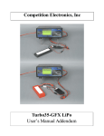
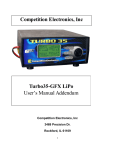
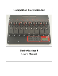
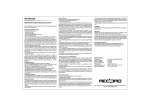
Competition Electronics, Inc
Turbo35-GFX LiPo/LiFe
User’s Manual Addendum
1
Introduction
This enhancement makes it possible to charge 1,2 and 3 cell LiPo and LiFe battery packs with the T35GFX. Now you can have the accuracy and reliability of the T35-GFX for LiPo and LiFe charging, as
well as NimH/NiCd charging.
Safety Considerations
WARNING: Please read before using your Turbo35-GFX charger/discharger:
IMPORTANT SAFETY INSTRUCTIONS AND WARNINGS
• You must read these safety instructions and warnings before using the Turbo35-GFX battery charger.
• Lithium Polymer batteries are volatile. Failure to read and follow the below instructions may result in fire,
personal injury and damage to property if charged or used improperly.
• Competition Electronics, Inc, its distributors or retailers assume no liability for failures to comply with these
warnings and safety guidelines.
General Guidelines and Warnings
1. Always and only use the corresponding charger/discharger mode for a given cell chemistry. Never
2.
3.
4.
5.
6.
7.
8.
9.
10.
11.
attempt to charge and discharge a cell chemistry of a given type using any operational mode intended
for that of another chemistry type. Failure to do so may cause a fire, which may result in personal injury
and property damage.
Always use the sense leads. LiPo/LiFe operations require precise voltage sensing; damage to LiPo/LiFe
packs may occur if you fail to use the sense leads.
Never charge batteries unattended. When charging batteries you should always remain in constant
observation to monitor the charging process and react to potential problems that may occur.
If at any time you witness a battery starting to balloon or swell up, discontinue the charging or
discharging process immediately, disconnect the battery and observe it in a safe place for
approximately 15 minutes. This may cause the battery to leak, and the reaction with air may cause the
chemicals to ignite, resulting in fire.
Since delayed chemical reaction can occur, it is best to observe the battery as a safety precaution.
Battery observation should occur in a safe area outside of any building or vehicle and away from any
combustible material.
Wire lead shorts can cause fire! If you accidentally short the wires, the battery must be placed in a safe
area for observation for approximately 15 minutes. Additionally, if a short occurs and contact is made
with metal (such as rings on your hand), severe injuries or burns may occur due to a battery pack's
ability to supply massive amperage.
A battery can still ignite even after 10 minutes.
In the event of damage sustained to a pack due to an R/C vehicle crash or other trauma, avoid any
charging or discharging of a LiPo or LiFe battery until you have placed it in a safe open area away from
any combustible material and observed it for approximately 15 minutes.
Never store, charge or discharge battery pack inside your car in extreme temperatures, since extreme
temperature could ignite fire.
Monitor the condition of your packs, especially LiPo and LiFe packs, and discontinue use when
performance degrades or changes significantly.
OBSERVE PROPER POLARITIES BETWEEN CHARGER AND PACK WITHOUT FAIL.
2
Charging/Discharging Process
1. Never charge/discharge batteries unattended.
2. Charge or Discharge in an isolated area, away from other flammable materials.
3. Let battery cool down to ambient temperature before charging.
4. Do not charge/discharge battery packs in series. Charge each battery pack individually. Failure to do so
may result in incorrect battery recognition and charging functions. Overcharging may occur and fire may
be the result.
5. When selecting the cell count or voltage for charging purposes, select the cell count and voltage as it
appears on the battery label. As a safety precaution, confirm the information printed on the battery is
correct.
6. Selecting a cell count other than the one printed on the battery (always confirm label is correct), can
cause fire.
7. You must check the pack voltage before charging/discharging. It is not advisable to attempt to
charge any LiPo pack if open voltage per cell is less than 3.3v. If you insist and the per cell voltage
is greater than 2.3 volts, the Turbo35-GFX will charge the pack at a reduced current for 2 minutes in
an attempt to reach at least 3V per cell. However, chances are the pack is damaged and will need
replacement. Likewise a reduced limited time charge will be initiated if you attempt to charge any
LiFe pack and the voltage is less than 2.5V/cell but greater than 2.0V/cell
8. CEI recommends charging at 1C rate or less (mAHr capacity of the battery/1000 in units of amperes),
unless the manufacturer specifically recommends otherwise.
Caring for Battery
1. Use caution to avoid puncture of the cell. Puncture of cells may cause a fire.
Operating Temperature
Typical Charge temperatures:
Typical Discharge temperatures:
32 to 113 degrees F
32 to 140 degrees F
1. Consult the specific manufacturer's data sheet for temperature data before charging or discharging a
LiPo or LiFe battery.
2. Let battery cool down to an ambient temperature before charging.
3. During discharge and handling of batteries, do not exceed 160 degrees F.
Significant Changes in the Turbo-GFX Charger
In order to add the LiPo capability, the scrolling help message system in the Turbo35-GFX was
eliminated. In order to add LiFe capability, the motor run function was also eliminated.
There are 5 setups for the NimH/NiCd function, 5 setups for the LiPo mode, and 5 setups for the LiFe
mode.
However, no other functionality was removed.
Navigating the LiPo or LiFe screens is no different than navigating the original NimH/NiCd screens,
with this exception: not all the calculated and measured data produced with NimH/NiCd packs makes
3
sense with LiPo or LiFe packs, so certain data has been eliminated in the LiPo mode.
New Higher Charge Rate
The Turbo35-GFX can now charge at up to a 20A rate (limited to 150 watts dissipation internally.)
Connecting the Turbo35-GFX to a LiPo/LiFe Pack
The hazards to both the battery and operator associated with shorting out or reversing polarity to LiPo
or LiFe packs make it essential that care is taken with connections between the Turbo35-GFX and the
pack. Smaller packs, such as transmitter packs or packs used for airplanes often come with a pin and
socket type connector, or a Dean's connector already assembled to the pack. If the connector ampacity
is sufficient for the discharge rate, it is suggested that you obtain a mating connector and afix it to the
GFX contacts in such a way that no short or polarity reversal is possible.
Larger packs such as those intended for R/C cars, often have low resistance, gold-plated barrel-type
connectors. In this case, CEI recommends obtaining the proper mating connectors and connecting them
to the Turbo35-GFX output leads in such a way that shorting of the pack is not possible. In this case, it
is recommended that similar proper mating connectors be directly attached to the Turbo35-GFX output
leads.
For convenience, you can use suitable connectors, such as Dean's connectors, on the sense and power
leads. Then, make plug-in harnesses for different pack types; terminate the NimH/NiCd harness with
the usual large and small alligator clips. Terminate the harness with a pair of high quality barrel
connectors specifically designed to mate with the pack.
CEI DOES NOT recommend using alligator clips or any dissimilar connector to directly connect to the
LiPo/LiFe pack's recessed terminals. In addition, avoid lots of floppy alligator-clipped connections
with LiPo/LiFe packs. Make the connections as simple as possible, and as short as practical.
Sense Leads
ALWAYS USE THE SENSE LEADS.
If your pack has high current barrel connectors such as those mentioned above, then it is best if you
mate the sense leads with their respective polarity power leads directly at the barrel connector. Crimp
or solder both power and sense lead directly into the mating barrel connector. Soldering is the the most
foolproof method; however, soldering is not always necessary, especially where the sense leads are
concerned. In any case, always try to connect the sense leads as close to the actual cell contacts as
possible, and try to assure that current through the sense leads does not travel through any more
connections than is necessary.
CAUTION: Inadvertent shorting of battery leads may cause fire or
explosion!
These battery packs are capable of huge amperage and so extreme caution should always be used when
creating and using wiring networks to charge and discharge these packs. It is recommended that you
work on one wire at a time and place insulating devices such as tape over other exposed connections to
avoid the possibility of shorts.
4
Making the Proper Connections when Charging or Discharging a LiPo or
LiFe Pack
There are legitimate occasions when you may choose to forgo using a balancer during charging, for
example, in order to charge at a higher rate.
In addition, you may be running a high current discharge on your LiPo/LiFe pack. It is important to
realize that improper use or connection of the sense leads during charge or discharge can result in
damage to the pack or overcharge, leading to the unpleasant surprise of disqualification when the pack
is inspected by technical personnel at a race. To avoid these unpleasant outcomes, you need to apply
the principals outlined above.
Here is the best way to connect the sense leads when charging or discharging a LiPo or LiFe pack
configured with the separate balance connector.
In this case, the sense leads are connected to the balance plug; you will want to connect them to the
pins which correspond to the “outside” of the pack, that is, those pins across which the entire pack
voltage appears. This gives the sense leads a direct and exclusive connection to the pack for the best
voltage reading accuracy during charge and discharge. In almost every case this will be the two pins
located at the outsides of the connector; you can check by measuring the voltage across the pins to see
if it is the same as the voltage across the large current carrying leads.
Observe proper polarities.
In the case of a LiPo or LiFe pack with bullet connectors, connect the sense leads directly at the main
bullet connectors by stripping back a small bit of insulation at the bullet connector, then clipping the
sense leads at these locations.
Connections for Single Cell LiPo/LiFe Packs
Single cell LiPo or LiFe packs by definition contain no balance connector; therefore all connections to
the pack must be made through the main power leads. In order to obtain maximum accuracy, you must
make effective use of the sense leads of the T35-GFX charger. CEI recommends creating a special
5
harness assembly for single cell packs, as shown below.
Note that the sense leads are connected through a dedicated connector to the other side of the power
connector. This way, error due to any significant source of voltage drop across the power connector is
eliminated.
It is strongly recommended that you use two different types of connectors to avoid accidentally
plugging them together the wrong way. A servo connector or something similar would be a good
choice for the sense lead connections.
Again, in the case of a single cell LiPo or LiFe pack with bullet connectors, connect the sense leads
directly at the main bullet connectors by stripping back a small bit of insulation at the bullet connector,
then clipping the sense leads at these locations.
Important: Using an External Balancer with the T35-GFX
NOTE: Make sure the balancer you have is compatible with the chemistry you are using.
LiPo and LiFe cells have different voltage levels and if you are planning on balancing a pack of a
particular chemistry you must obtain a balancer that is compatible with that chemistry. Consult the
balancer manufacturer for information concerning this issue to make sure the balancer you get is
compatible with the chemistries you are using.
When using an external balancer with the T35-GFX you need to be aware of the fact that it is to be
connected only during charging. You must completely disconnect the balancer during discharge, or
cycle operations.
As already mentioned, the Turbo35-GFX incorporates special voltage sense leads so that it can
measure voltage with greater precision under all conditions. However, this does make achieving the
proper connections more complex, especially when charging LiPo/LiFe packs using external balancing
devices. Because accurate voltage control is a must when working with LiPo/LiFe packs, proper
connection of the sense leads is critical.
6
To reiterate: you must use the sense leads when working with LiPo or LiFe packs!
In order to get good results when working with LiPo or LiFe packs, it is important to understand these
two principles:
●
Connection of the sense leads should always be made as close as possible to the LiPo/LiFe pack
terminals, both electrically and physically.
●
The more current there is flowing through a connection or wire, the more voltage drop will
occur across that connection or wire, and the more error there will be in the voltage reading if
that connection or wire is between the pack and the sense leads.
Now, with these two principles in mind, let's look at a couple of diagrams that show a hypothetical
balancer used with the T35-GFX to charge-balance 2C LiPo packs. (The same principles will apply for
LiFe packs.)
The first, below, is a diagram showing the connections for a LiPo pack with bullet connectors. Note
that this pack has two high current bullet connectors which serve for both balance and charge functions,
and a separate, smaller bullet connector in the center which is intended for balancing. (That does not
mean that it could not be used for charging, but current limitations of the smaller connector must be
observed.)
Note the following:
●
The GFX's heavy current-carrying charge leads connect directly to the input of the balancer.
●
The balancer's output leads, equipped with the proper harness, are connected to the LiPo pack
per the balancer manufacturer's instructions.
●
The GFX's sense leads are connected directly to the large bullet connectors on the LiPo pack.
A few things need to be said about this hookup:
7
●
Do not charge at a higher rate than the balancer can endure.
●
Observe all proper polarities.
●
Observe the balancer manufacturer's directions.
●
Make sure that the sense lead connections are made very close to the pack connectors.
In this case, we can be assured that under normal circumstances, the voltage drop across the bullet
connectors will be very low, as they are high quality connectors designed for this purpose, so
physically, the best you can do is to strip back the insulation right where the high current charge leads
are soldered to the bullets and clip the sense leads at that point. There is a lot of current flowing
through the power leads, but very little flowing through the sense leads, so in this case the only critical
aspect of the connections of the sense leads is that they be made as close as possible to the bullet
connectors.
Let's consider how to connect another popularly configured LiPo pack:
Here, the pack has a Dean's connector for the main power connections and a special pin and socket
connector for the balance function.
The recommended connections for this pack are counterintuitive because in this case the charging
occurs through the balance plug and the sense leads are connected to the Dean's plug. Inside a pack
such as this, the balance and power connections go to exactly the same place, and as long as we don't
exceed the current carrying capacity of the balance connector and it's smaller wires, this arrangement
will work very well.
In this case the high current (whatever the connector and balancer will allow, since the GFX's charge
rate capacity will almost certainly exceed the balancer's capability) flows through the balance plug, and
that leaves the Dean's connector free to be used as a sense connection.
You should be aware of the fact that any connector/connection can fail and cause inaccuracies or
hazardous conditions to occur.
If proper principles are followed, special harnesses can be constructed to make implementing these
connections easy and convenient. Contact Competition Electronics for details.
8
Final Notes About Balancers
One should not assume that every balancer is compatible with the T35-GFX. Be alert for possible
errors induced by the balancer. It is possible, though unlikely, that some balancers will not work
correctly, or at all with the T35-GFX due to incompatibility issues.
Balancing with the Turbo35-GFX Alone
You can balance a pack using only the Turbo35-GFX, as follows:
●
Set up the GFX for a 1C charge.
●
Charge each cell of the pack individually, using the proper combination of balance and main
charge connections on the LiPo or LiFe pack.
Just make sure that
●
You do not exceed the current rating of the balance connector.
●
You follow the principles outlined above when connecting the voltage sensing leads.
Powering up the Turbo-GFX: Selecting Cell Type
The first thing you will notice after the T35-GFX shows the sign on screen is the Cell Type selection
screen. Here, you can use the rotary encoder dial to select either NimH/NiCd, LiFe or LiPo chemistry.
The unit defaults to NimH/NiCd but if you select LiPo or LiFe and then store the setup, the next time it
will default to the selected mode. A scrolling message will appear at the bottom of the screen indicating
that the T35-GFX is in the selected mode.
NimH/NiCd mode
The NimH/NiCd operation mode is unchanged from the previous version, except that there will be a
scrolling message at the bottom indicating that the unit is in NimH/NiCd mode. Please consult the
original manual, found at www.competitionelectronics.com under Turbo35-GFX if you have questions.
LiPo and LiFe Modes
The Turbo35-GFX LiPo and LiFe modes allows charging of LiPo or LiFe packs consisting of 1, 2 or 3
cells at up to 20000 mAHr rates (limited to total of 150 watts internal power dissipation.)
Both LiPo and LiFe packs require a constant current charge process when the voltage is below the
CC/CV crossover voltage setpoint; they only differ in the magnitude of the crossover voltage. A LiPo
cell crossover voltage is typically 4.2 volts, while a LiFe cell is 3.6 volts. After the per-cell voltage
threshold is reached, the charge mode will switch into a constant voltage mode and maintain the pack
voltage at (crossover voltage setpoint times # of cells) until current drops to roughly 3% of the mAHr
setpoint. At this point the charge is terminated. Older T35-GFX units have fixed crossover voltage
setpoints. Firmware revision 3.00 crosses over at 4.2 volts for a LiPo cycle. Later revisions cross over
at 4.22 volts. Subsequent revisions are adjustable. A firmware upgrade is available.
The Turbo35-GFX can discharge a LiPo or LiFe pack at up to a 35 amp rate. The discharge is
terminated when the pack voltage reaches (3V times # of cells) while under load for a LiPo pack, and
9
(2.5V times # of cells) for LiFe packs.
Charging with the Turbo-GFX
Charge display pages have been added to the Turbo35-GFX for LiPo and LiFe operations which are
very much like the existing charge page for NimH/NiCd packs. There are three significant settings for
charging/discharging LiPo or LiFe battery packs, as follows:
Max Charge Seconds
This is a user-settable safety time limit that will shut off the charge and signal an error if the charge
time becomes equal to the setting. It is just another safety device which may be useful in the event of a
malfunctioning LiPo or LiFe pack. You should determine the typical charge time for a given LiPo/LiFe
pack at a given mAHr rate, and then set this just a bit longer.
It is also useful as a way to put a partial charge into a pack for the purpose of storage.
No of Cells
Always make sure the number of cells set into this setting agrees with the number of cells specified on
the LiPo/LiFe pack.
Charge mAHrs
Set this to the mAHr rating on your LiPo/LiFe pack label. The Turbo35-GFX will charge at the ampere
rate which will result in full mAHrs delivered in 1 hour's time. For example if you have a 3200 mAHr
pack, set the mAHr setpoint for 3200 and the Turbo35-GFX will charge at a rate of 3.2 amps.
Some manufacturers of LiPo or LiFe packs specify the ability to charge at 2C, or even 3C rates. Check
your manufacturer's pack data to determine if this is acceptable to your pack. At the time of this writing
it is generally the case that charge rates higher than 1C can shorten the life of the LiPo/LiFe pack.
NOTE: Unless specifically allowed by the manufacturer of the LiPo/LiFe pack in question, never
exceed a 1C charge rate.
Xover V/Cell
This setting allows you to adjust the voltage at which the LiPo/LiFe charge process crosses over from
constant current (CC) to constant voltage (CV). In the case of LiPo packs, the range of adjustment
spans from 4.15V to 4.25V per cell. For Life packs, the range is 3.55V to 3.65V. Don't forget this when
setting the parameter: for example, a two cell pack will have an actual crossover voltage of twice the
setting, a three cell will have three times, etc. This will allow you to get maximum performance from
your cells and still not exceed ROAR specs for LiPo max voltage after charging.
10
Under and Overvoltage Considerations
LiPo charge will be disabled and an error message displayed if the pack voltage exceeds 4.3V per cell
or if it is less than 2.3V per cell.
If the LiPo pack voltage is between 2.3V and 3V per cell, the Turbo35-GFX will try to charge the pack
at approx. 10% of the mAHr rate setpoint for 2 minutes in an effort to restore the pack voltage to 3V
per cell. If the pack does not return to this level after 2 minutes, the charge cycle is terminated and an
error message is displayed.
LiFe charge will be disabled and an error message displayed if the pack voltage exceeds 3.8V per cell
or if it is less than 2.0V per cell.
If the LiFe pack voltage is between 2.0V and 2.5V per cell, the Turbo35-GFX will try to charge the
pack at approx. 10% of the mAHr rate setpoint for 2 minutes in an effort to restore the pack voltage to
2.5V per cell. If the pack does not return to this level after 2 minutes, the charge cycle is terminated and
an error message is displayed.
Discharging with the Turbo-GFX
The Turbo35-GFX is capable of discharging continuously at up to 35 Amps. For some LiPo or LiFe
packs, this will cause the pack to exceed it's maximum safe temperature. Usually, this is around 140
deg F. Exceeding the maximum temperature can cause fire or explosion. Consult the manufacturer's
data sheet for details concerning the maximum temperature for your pack. Always observe maximum
discharge rates specified by the manufacturer, as well. If in doubt contact them and ask them directly.
The Discharge display page contains three settable parameters:
Discharge Amps
Settable between .5 and 35 amps. Observe all precautions under “Discharging with the Turbo35-GFX,
above.
No of Cells
Always make sure the number of cells set into this setting agrees with the number of cells specified on
the LiPo/LiFe pack.
AIR On/Off
For higher charge rates, the Turbo35-GFX will measure actual internal resistance at 121 seconds into
the discharge cycle. AIR measurement is disabled for discharge rates of 10 amps and below.
Under and Overvoltage Considerations
NOTE: As with charging, there are under and over voltage checks built in which will terminate
discharge if it can be determined that there is an abnormality.
11
Cycling with the Turbo-GFX LiPo
Cycling in LiPo or LiFe mode works as you would expect; it first runs the charge and then the
discharge functions.
Storing and Retrieving Program Setups
Storage and retrieval of setups works the same way as with the original T35-GFX, however, there are
now 5 setups available for each of the three chemistries, NimH/NiCD, LiPo and LiFe. See the T35GFX manual for details.
Generic setups have been provided for all three chemistries as a starting point and a convenience to the
user. It is the responsibility of the user to understand, select and adjust these setups to suit specific
packs.
This manual and its contents ©2007-2011 Competition Electronics, Inc.
Competition Electronics, Inc
3469 Precision Dr.
Rockford, IL 61109
12