1
7 5 5 0 S ta te R o u te 5 & 2 0 B lo o m fie ld , N Y 1 4 4 6 9 -9 3 8 9
FA X # : 7 1 6 -6 5 7 -6 1 5 3 Te l.# 7 1 6 -6 5 7 -6 1 5 1
h ttp ://w w w .v e lm e x .c o m E m a il: m itc h @ v e lm e x .c o m
MODEL 86MM-1
USER'S GUIDE
One Motor
STEPPING MOTOR CONTROLLER/DRIVER
11-17-86 Rev 2-10-87
Reformatted 1-16-98
Contents
INTRODUCTION
FEATURES
SETUP
CAUTIONS, 4
I/O, 5
Turn ON, 5
FRONT PANEL INPUT
JOG/SLEW MODE, 6
DIGITIZING, 6
MENU SELECTION, 7
CLEAR button, 7
PROGRAMMING
COMMANDS with VARIABLES
Settable, 7
200 step/rev, 400 step/rev, 7
Backlash compensation, 7
Programmable, 8
Advance per step (table), 9
IMMEDIATE COMMANDS, 10
MEMORY/BATTERY RETENTION, 12
Bytes of memory for commands (table), 12
EXAMPLES, 13
PROGRAMMING FROM BASIC ON A IBM TYPE COMPUTER, 15
16
LINKING CONTROLS,
TROUBLESHOOTING PROCEDURE, 18
HARDWARE
LIMIT SWITCHES,
CABLES, 20
BATTERIES, 20
20
SPECIFICATIONS
FUNCTIONAL, 21
MOTOR COMPATIBILITY, 21
PHYSICAL, 21
ELECTRICAL REQUIREMENTS,
ENVIRONMENTAL, 21
21
2
INTRODUCTION
The 86MM is a programmable stepping motor control. The Control incorporates a one-chip
microcomputer that has on-chip RAM and ROM. The RAM is available for storage of a user-entered
program and motion parameters. Commands and data are entered either through the front panel keypad
or over the RS-232C interface from any host computer, terminal, or programmable controller having an
RS-232C port. Specialized Commands provide simple and efficient entry of complex, yet compact,
programs. Short programs are automatically retained in the portion of RAM which is battery-backed.
FEATURES
A complete microcomputer-based Control with nonvolatile user memory and motor drive in one package.
Motor Resolution can be set to 200 or 400 steps per revolution.
JOG/SLEW mode allows motor to be jogged one step or slewed from 16 to 2850 steps/second from the
front panel (joystick emulation).
A Digitizing function can be utilized with a host terminal connected as a readout of motor position.
Menu LEDs provide command-selection from the front panel.
Keypad with audible and tactile feedback provides data-entry at the front panel.
RS-232C Port connected to a host allows Command and Data entry, Polling for status, and Absolute
Position. Up to 255 controls can be operated from the same RS-232 port.
Acceleration/Deceleration settable from 8000 to 56000 steps/sec2 in 8000 step/sec2 increments.
Speed settable from 16 to 3000 steps/sec in 1 step/sec increments.
Incremental Index distance is programmable from +1 to +1,048,575 steps.
Programmable Return-to-Zero position.
Loop Commands provide from one to continuous repeat operations.
Programmable Pauses from 100 milliseconds to 13.65 minutes.
A User Output can be programed to turn ON and OFF an external solid state or reed relay.
A User Input can be utilized in a program as a WAIT for external switch or relay closure.
Backlash Compensation can be set to automatically finish every index approaching from the positive
direction.
Run, Reset, Output, Input, and RS-232C connections are accessible at a removable terminal block on
the front panel.
Limit Switches for CW and CCW directions are provided with plug-in connection to UniSlide "J"
assemblies. Limits can be used for "homing."
Automatic Power Down reduces power consumption by de-energizing the motor when at a standstill.
3
Single Step mode is provided for debugging programs or as a controlled interrupt.
The Control can be polled for its status at any time; additionally a ready prompt (">") is automatically sent
to the host when a program has finished.
Capable of running large motors, up to 10 amps total (5 amps/phase).
Twelve month Limited Warranty.
SETUP
* * CAUTION * *
* HAZARDOUS VOLTAGE, DO NOT REMOVE CONTROL PANELS
OR COVER
* DO NOT CONNECT OR DISCONNECT MOTOR WHEN POWER
IS "ON"
* HIGH TEMPERATURE, CONTROL SHOULD BE KEPT AT LEAST
6 INCHES FROM ANY OBJECTS
* AIR MUST CIRCULATE THROUGH AND AROUND CONTROL,
DO NOT BLOCK AIR VENT IN BOTTOM OF CONTROL
* NEVER USE IN AN EXPLOSIVE ENVIRONMENT
* IN INDUSTRIAL ENVIRONMENTS, THE CONTROL MUST BE
PROTECTED TO PREVENT METAL CHIPS FROM FALLING
INTO IT
* SEVERE ELECTRICAL DAMAGE MAY RESULT IF OBJECTS
FALL INTO THE CONTROLS HEAT SINK
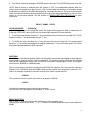
1. Connect cables to motor and limit switches.
CAUTION: Never connect or disconnect motor with power ON, this may result in severe damage to
motor drives.
2. Plug Control into 120VAC outlet.
4
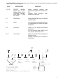
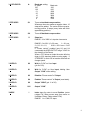
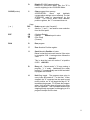
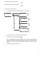
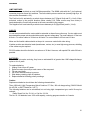
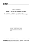
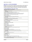
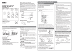
Input/Output (I/O) connections other than motor, AC power, and limit switches are located at a removable
terminal block on the front panel.
PIN #
DESCRIPTION
PURPOSE
1,2,3,12
RS-232C
Interface
(Signal Gnd, Tx, Rx,
Chassis Gnd). 300 to
7200 Baud, 7 Data bits,
Even parity, 2 Stop
bits, ASCII
Allows
constant
program
and
parameter changes from a computer or
P.C.
Provides visual feed-back when
attached to a terminal.
4,5
Remote Run
Allows program-Run from an external
switch or relay.
6,7
Reset
Can be used as a emergency stop, or
to synchronize the Control with other
equipment.
8,9
User Input
Used as a "Go" signal from external
equipment.
Pin 9 is internally held "HIGH" by 1K
ohm resistor connected to +5V.
10,11
User Output
Signals or actuates external equipment
between moves.
Capable of powering a Solid State or
Reed Relay.
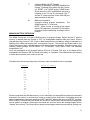
I/O
+5V
1
SIGNAL
GND
2
3
DATA
IN
DATA
OUT
4
5
o
o
REMOTE
RUN
SWITCH
6
7
o
o
RESET
SWITCH
RS-232
300 to 7200 Baud,
7 Data bits, Even
parity, 2 Stop
bits, ASCII
(see "A-" command to set Baud rate)
8
9
o
o
USER
INPUT
SWITCH
SOLID
STATE
RELAY
10
11
12
CHASSIS
(10ma
GND
max)
USER
OUTPUT
(normally +5V)
3
4
1
2
5
3. Turn ON the Control by pushing the POWER switch to the right. The JOG/SLEW light will come ON.
NOTE: Data in memory is retained when the Control is "OFF" by rechargeable batteries within the
Control, that are charged when the Control is "ON". A loss of data retention due to low battery voltage
is indicated by a flashing of the LEDs and beeping for 2 seconds after turn-on. This may be the situation
with a new Control that has not been operated long enough to fully charge the batteries, or if four or more
weeks of non-use have elapsed. See the section on MEMORY/BATTERY RETENTION for more
information.
FRONT PANEL INPUT
JOG/SLEW MODE:
* JOG/SLEW
1.
With the Control in the JOG/SLEW mode, the motor can be jogged one step, or slewed from 16
to the last STEPS/SEC value (SLEW will not exceed 2850 steps/sec) in either direction.
2. To JOG the motor positive, press the "1" key momentarily; the motor will move one step CW. To JOG
negative hold the "-" key down and press the "1" key.
3. To SLEW the motor, hold down the "1" key, the motor will run at 16 steps/sec. To increase speed
press the " | " key until the desired speed is reached. Release the "1" key to decrease speed. The motor
accelerates and decelerates at 8000 steps/sec2 .
DIGITIZING
The 86MM stores its absolute position (relative to the position when power was applied or when registers
were zeroed) in memory until the Control is turned-off. The absolute register reflect the accumulated
distance from operating the motor in the JOG/SLEW mode and/or under program control. This register
can hold from -8388608 to +8388608 steps.
With a host terminal or computer connected via the RS-232C interface, the Control can be used as a
digitizer. In the JOG/SLEW mode the 86MM will send motor position to the host when it receives a "D".
Here is an example of what the host would receive when motor is at absolute 201:
+0000201
This is what the host will receive if the motor is at negative 1294010:
-1294010
A linefeed and carriage return follows the above values.
The host can "zero" the registers by sending a "Z" to the Control.
MENU SELECTION
The " | " and " | " keys are used to make selections on the front panel menu.
Pressing keys other than the "RUN", " | " or " | " results in an audible feed-back from a buzzer within the
86MM.
6
Refer to the next section on COMMANDS with VARIABLES for proper values to enter.
If the Control contained a program the last time the POWER was turned OFF, the Control will prevent
any menu selection past ACCEL/DECEL. This feature limits editing to baud rate and
acceleration/deceleration.
To "CLEAR" a program from memory press the recessed CLEAR button on the front panel using a pen
or pencil.
Simple Example
Below is an example that will run the motor 200 steps CW.
From a computer send:
E I200,R
NOTE: The "E" is sent first to get the Control ON-LINE ( both yellow lights on front panel lit ).
From the front panel:
Push the " | " key until the light next the INDEX is lit, press the "2" key, "0" key, "0" key,
"Ent" key, "Run" key.
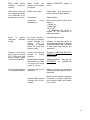
PROGRAMMING
COMMANDS with VARIABLES
Front Panel
Front Panel &
Function
Menu
RS-232C Input
First character applies only to RS-232C input
Settable (one-time entry in a program)
* ACCEL/DECEL
A
Acceleration and Deceleration.
SET
RANGE: 1 to 7 or 9 to 15
1 to 7 sets motor to 200 steps/rev
(1 being
8000 steps/sec2, 2 being 16000 steps/sec2, 3
being 24000 steps/sec2, etc.)
9 to 15 sets motor to 400 steps/rev
(9 being
8000 steps/sec2, 10 being 16000 steps/sec2, 11
being 24000 steps/sec2, etc.)
NOTE: Acceleration and Deceleration only occurs
above 236 steps/sec.
7
* ACCEL/DECEL
A-
Baud rate setting.
A- value
207
103
51
25
16
12
8
Baud rate
300
600
1200
2400
3600
4800
7200
* STEPS/SEC
S-1
Turns on backlash compensation.
Whenever the motor makes a negative Index, 16
steps will be added. The motor will then reverse,
moving positive 16 steps (every Index will finish
approaching positive).
* STEPS/SEC
S-0
Turns off backlash compensation.
* STEPS/SEC
S
Steps/sec.
RANGE: 16 to 3000 in 1 step/sec increments
RANGE: 0 to 8191 (0 = 20 usec,
1 = 0.1 sec,
2 = 0.2, 10 = 1.0,
8191 = 819.1 sec = 13.65
min)
If "Pause control" enabled (see U2 and U4
commands) the USER OUTPUT will go "LOW" for
the duration of the Pause.
When a "P0" follows an Index the motor will slow
down to 236 steps/sec before moving again. If
STEPS/SEC is set to 236 or less the motor will not
change speed.
* USER I/O
U0
Wait for "LOW" on User Input
(pin 9 of I/O).
* USER I/O
U1
Wait for "LOW" on User Input, holding User
Output "LOW" while waiting.
* USER I/O
U2
Disables "Pause control" of Output.
* USER I/O
U4
Enables "Pause control" of Output (reset state).
* USER I/O
U8
Output "HIGH" (pin 11 of I/O)
* USER I/O
U16
Output "LOW"
* INDEX
I
Index steps for motor to move Positive. (motor
rotates CW, Slider moves away from motor on
UniSlides, Rotary Tables rotate CCW)
RANGE: 1 to 1,048,575 steps
8
* INDEX
I-
Index steps for motor to move Negative. (motor
rotates CCW, Slider moves toward motor on
UniSlides, Rotary Tables rotate CW)
RANGE: 1 to 1,048,575 steps
* INDEX
I0
Index motor to "Absolute Zero".
"Absolute Zero" is established when the Control is
turned "on", a "Z" command, RESET, or CLEAR
button is used.
NOTE: Operating the motor in the JOG/SLEW
mode does not change the location of "Absolute
Zero"
* INDEX
IM
Move Positive to limit switch, Index off limit
entered value, and zero Absolute Position
register.
RANGE: 1 to 65,535 steps
Caution: Set Speed to less than 800 Steps/Sec
prior to this command to prevent damage from the
sudden stop when limit switch is encountered.
* INDEX
IM-
Move Negative to limit switch, Index off limit
entered value, and zero Absolute Position
register.
RANGE: 1 to 65,535 steps
Caution: Set Speed to less than 800 Steps/Sec
prior to this command to prevent damage from the
sudden stop when limit switch is encountered.
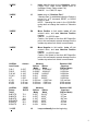
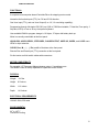
UniSlide
Lead Screw
P40,C
P20,B
P10,W1
P5,W2
WF
K1,Q1
K2,Q2
K4,Q4
UniSlide
Rotary
Table
B4872TS
B4836TS
B4818TS
B79180TS
B7990TS
B7945TS
* LOOP
Adv/rev
0.025"
0.050"
0.100"
0.200"
1.000"
1.00 mm
2.00 mm
4.00 mm
GEAR
RATIO
72:1
36:1
18:1
180:1
90:1
45:1
L0
Adv/step
200/rev
400/rev
Mode
Mode
0.000125" 0.0000625"
0.00025" 0.000125"
0.0005"
0.00025"
0.001"
0.0005"
0.005"
0.0025"
0.005 mm 0.0025 mm
0.010 mm 0.005 mm
0.020 mm 0.010 mm
Speed at 1000
steps/sec
(200/rev Mode)
0.0125 ips
0.2500 ips
0.5000 ips
1.0000 ips
5.0000 ips
5.00 mm/sec
10.00 mm/sec
20.00 mm/sec
Adv/step
200/rev
400/rev
Mode
Mode
0.025o
0.0125o
0.050o
0.025o
o
0.100
0.050o
o
0.010
0.005o
o
0.020
0.010o
o
0.040
0.020o
Speed at 1000
steps/sec
(200/rev Mode)
25o/sec
50o/sec
100o/sec
10o/sec
20o/sec
40o/sec
Loop continually from the beginning.
9
* LOOP
L-0
Sets the "loop-marker" at the current location in
memory. All loops (except L0) to the right will
branch to here. Loops to the left branch to the
beginning. The maximum number of loops a
program can hold is 10 on both sides of the loopmarker (excluding L0).
NOTE: This Command can be used only once in
a program.
* LOOP
L
Loop from beginning or loop-marker.
RANGE: 2 to 255 loops
Actual number of loops is one less the value
entered.
Loops can be nested. The following example
loops equal 100,000 (actual loops is one less or
99,999 times):
L100 L100 L10
NOTE: When any Loop reaches its last count the
non-loop command directly preceding the Loop
will be ignored.
To prevent a preceding Index from being ignored
use one of the "U" commands or an "S" command
before the Loop command.
For example, this program will index the motor
positive and negative 200 steps exactly 100,000
times, the "U4" command is used as a "dummy":
I200 I-200 U4 L100 L100 L10
* LOOP
L-
Loop from beginning or loop-marker alternating
direction of motor Indexes.
RANGE: 2 to 255 loops
Actual number of loops is one less the value
entered.
Loops can be nested. The following example
loops equal 100,000 (actual loops is one less or
99,999 times):
L-100 L100 L10
NOTE: When any Loop reaches its last count the
non-loop command directly preceding the Loop
will be ignored.
To prevent a preceding Index from being ignored
use a "U" command or an "S" command before
the Loop command.
IMMEDIATE COMMANDS (not stored in a program)
E
Enable RS-232C communication. (Both yellow
LEDs on front panel will light.) The Control must
be in the JOG/SLEW Mode to respond to this
command.
10
CLEAR (button)
| or |
D
Disable RS-232C communication.
Returns to JOG/SLEW Mode. Also, the "D" is
used for digitizing in the JOG/SLEW Mode.
C
Clear program from memory.
ACCEL/DECEL,
Baud,
and
backlash
compensation settings are not affected. The last
STEPS/SEC value is "remembered" by the
Control. The CLEAR button zeros absolute
position registers, the "C" command does not.
Keys:
DEL
Delete current value "keyed-in".
Also the " | " and " | " are used for menu selection
<from the front panel.
(Carriage Return)
(Space)
Enters keyed in value.
(Line Feed)
(Comma)
ENT
CR
SP
LF
,
RUN
R
Run program.
Z
Zero Absolute Position register.
X
Send Absolute Position of motor.
Below is what the host would receive if the motor
is at negative 1200. A carriage return follows the
value.
-0001200
This is what the host will receive if at positive
91203 +0091203
B
Busy poll. Control sends "<" if busy running a
program, ">" if ready. Additionally the ready
prompt (">") is automatically sent to the host when
a program has finished.
H
Hold flag toggle. The program stops prior to
every index and sends a ":" to the host. When
stopped, the "X" command can be used to read
motor position, an "H" will toggle the flag off, "K"
terminates the program, "R" re-starts the program
where it left off and a stop will again occur after
the next operation. This Command allows single
stepping through a program for debugging or as a
program interrupt from the host.
11
T
Character Echo ON/OFF Toggle.
Normally all characters sent to the 86MM will be
echoed. Character Echo will be ON after "powerup", RESET, or a "CLEAR" by the CLEAR button.
When the echo is OFF the 86MM will still send a
response to the "X" and "B" commands. The "T"
and the "E" (used to get the Control ON-LINE) are
always echoed to the host.
K
Kill current operation.
Interrupts running program immediately. The
86MM sends the ">" to the host.
NOTE: When a motor is running at high speed
(above 700 steps/sec), command "K" interruption
may cause motor overshooting, resulting in loss of
position.
MEMORY/BATTERY RETENTION
The 86MM Control has 101 bytes of RAM memory for program storage. Data in the first 27 bytes of
memory is retained when the Control is "OFF" by rechargeable batteries within the Control, that are
charged when the Control is "ON". A loss of data retention due to low battery voltage is indicated by a
flashing of the LEDs and beeping for 2 seconds after "turn-on". This may be the situation with a new
Control that has not been operated long enough to fully charge the batteries. Data loss results in the
following default settings: ACCEL/DECEL =1, STEPS/SEC =1000, Baud =1200, and backlash
compensation "off".
From fully discharged to fully charged requires 30 hours of Control "ON" time. A full charge will be
maintained if the Control is "ON" for at least 45 min/day, or 5 hrs/week. The batteries have the capacity
to retain data in memory for 4 weeks of non-use.
The table below shows how many bytes of memory each command will use in a program.
Bytes of memory
Command
S
2
P
2
U0
1
U1
1
U2
1
U4
1
U8
1
U16
1
I
3
I3
I0
3
IM
3
IM3
L0
1
L
2
L2
All other commands use allocated memory, or are "immediate" (not stored).Each command is stored and
executed in the order it is received from a host or keyed-in at the front panel. Commands cannot be
added to the program if the power was turned "OFF" and "ON", which is the same as a RESET condition.
When a RESET condition has occurred the ACCEL/DECEL and the Baud rate are the only changes that
can be made to a program. When other commands are sent from a host the existing program will be
"cleared" from memory. The Control will not accept a new program whenbusy executing an existing one.
12
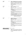
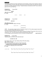
EXAMPLES
The following examples can be input manually from the front panel or sent by a host computer or terminal
over the RS-232C. For entries made from the front panel, the first letter refers to the Command selected
from the menu (LEDs) using the arrow keys. The space between commands is the "ENT" key on the front
panel; the "R" is the "RUN" key.
EXAMPLE #1,
Index 200 Steps
3 bytes RAM:
I200 R
I200 INDEX 200 steps
R RUN
++
START
EXAMPLE #2,
Auto-Reverse
END
6 bytes RAM:
I401 I0 R
I401 INDEX 401 steps
I0 INDEX to Zero (-401 steps in this case)
R RUN
START/END
++
:
:
::
NOTE: By connecting a toggle switch to Connections 4 and 5 of I/O, the above program can provide
a switch controlled continuous running auto-reverse.
The above example will dwell for 65 ms before reversing. By using a P0 command, this time will be
reduced to 4.2 ms. The motor will still accelerate and decelerate at the set rate.
In this example the motor will dwell for only 4.2 ms before reversing direction:
I401 P0 I0 P0 R
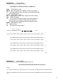
EXAMPLE #3,
9 bytes RAM:
Repeating Index two directions with wait and output
U1 I800 L10 L-2 R
U1 Wait for LOW on User Input holding Output LOW while waiting
I800 INDEX 800 steps
L10 Do 10 times (The actual number of times the program
is repeated will be one less the Loop value, and two less
for any non-Loop command directly preceding the Loop)
L-2 LOOP from beginning with reverse direction
R RUN
START/END
U
U
U
U
U
U
U
U
U
U
++++++++++
1
2
3
4
5
6
7
8
9
10
:
:
U
U
U
U
U
U
U
U
U
U
++++++++++
13
EXAMPLE #4,
20 bytes RAM:
Homing and looping using loop-marker
S700 IM-200 L-0 S1500 U1 I200 L11 S2000 I0 L4
S700
STEPS/SEC to 700
IM-200 Move to Negative limit, INDEX "off" 200, zero position.
L-0
Set loop-marker to here in program. Succeeding Loops will
branch to this point.
S1500 STEPS/SEC to 1500
U1
Wait for LOW on User Input, Output LOW while waiting
I200 INDEX 200 steps
L11
Do 11 times (The actual number of times the program is
repeated will be one less the Loop value, and two less
for any non-Loop command directly preceding the Loop)
S2000 STEPS/SEC to 2000
I0
INDEX to Zero
L4
Do 4 times from loop-marker
LIMIT SWITCH
START
| :
:
U
U
U
U
U
U
U
U
U
U
U
:+++++++++++ 1
1
2
3
4
5
6
7
8
9
10
11
:
::
U
U
U
U
U
U
U
U
U
U
U
+++++++++++ 2
1
2
3
4
5
6
7
8
9
10
11
:
::
U
U
U
U
U
U
U
U
U
U
U
+++++++++++ 3
1
2
3
4
5
6
7
8
9
10
11
:
::
U
U
U
U
U
U
U
U
U
U
U
+++++++++++ 4
1
2
3
4
5
6
7
8
9
10
11
END
EXAMPLE #5,
33 bytes RAM:
Several different Indexes, Pausing between each one
I100 P5 I250 P5 I400 P5 I550 P5 I600 P5 I1100 P5 I0
START
P
P
P
P
P
P
+++++++
:
:
::
END
14
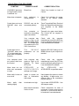
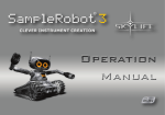
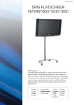
PROGRAMMING FROM BASIC ON A IBM TYPE COMPUTER
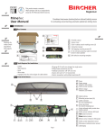
The procedure for programming the 86MM from BASIC is:
1.
Make the 3 wire RS-232 connection from the host computer to the 86MM.
Computer
SERIAL
25 pin Connector
2
3
7
86MM
I/O
Connector
3
2
1
If a shielded cable is used, connect the shield to connection 12 on the 86MM I/O.
2.
Turn ON the Control and the host computer.
NOTE: A framing error may occur on the host's receiver when the 86MM is turned ON or
reset while the host is ON. The host will display the "Device I/O error" message when the
BASIC program is started. To prevent this error turn ON the host after the 86MM or only
connect the RS232 cable after the host and the Control have been turned ON.
3.
Boot BASIC on the computer.
4.
Create a BASIC program that incorporates the following:
a.
Open the RS-232 port on the computer with an OPEN COM
statement.
(PC users can also use: “Terminal” program located
in Accessories in Windows 3.1 or “HyperTerminal” with Windows 95, set baud to
1200, Even parity, 7 data bits, 2 stop bits, and set flow control to None).
b.
Print "EZT" to the 86MM Control to get the Control ON-LINE, Zero
the Absolute Position Register and to Toggle echo off. The "Z" Zeros
the Absolute Position Register, that would have accumulated steps
if the motor had been run in the JOG/SLEW mode. The echo off
("T") will prevent the computer's receive buffer from filling with
unwanted characters.
c.
Print the 86MM program to the Control.
d.
Wait for the ready (">") prompt, indicating the 86MM program
has finished running.
e.
Perform data acquisition or control function for this motor
position.
f.
If desired, request motor position from the 86MM.
g.
Print another program to the 86MM.
NOTE: To prevent the new program from being added to
the last program in the 86MM, send the Clear ("C") command
prior to the new program.
15
The following example demonstrates a method for programming the 86MM over the RS-232 by sending
commands from BASIC.
90 REM 86MM-1 BASIC Example Program
95 REM Open RS-232 (COM1:), 1200 Baud, control lines disabled, ASCII
100 OPEN "COM1:1200,E,7,2,CS0,DS0,ASC" AS #1
105 REM Enable, Zero position register, Toggle echo off
110 PRINT#1,"EZT"
115 REM Clear any existing program, 1000 Steps/Sec, Index 1500 steps 120 PRINT#1,"C S1000 I1500
R"
130 GOSUB 500
135 REM Clear existing program, Index 900 steps
140 PRINT#1,"C I900 R"
150 GOSUB 500
155 REM Clear existing program, Index 1000 steps
160 PRINT#1,"C I1000 R"
170 GOSUB 500
175 REM Clear existing program, 3000 Steps/Sec, Index to zero
180 PRINT#1,"C S3000 I0 R"
190 GOSUB 500
390 PRINT "DONE RUNNING 86MM CONTROL"
400 END
499 REM Wait until ready (">") prompt appears in receive buffer
500 C$=INPUT$(1,#1)
510 IF C$ <> ">" THEN 500
515 REM Request motor position from 86MM and print on your computer 520 PRINT#1,"X"
530 INPUT#1,P
540 PRINT "MOTOR POSITION="; P; "STEPS"
550 REM Your routine for end of Index would go here
600 RETURN
LINKING CONTROLS
Users that require more than one motor can link 86MM Controls together. Multiple Controls can be
operated from a single RS232 port by linking. When linking multiple Controls together addressing is
accomplished by enclosing information in brackets. Information between brackets is relayed to
succeeding Controls. The number of brackets used determines the destination of the information. As
each Control receives the information, it removes a set of brackets and relays the remainder of the
instruction to the next Control. Up to 255 Controls can be linked together and programmed in this manner.
All the yellow and green LEDs on the Control's front panel will light when in this "relay mode". For
example, if four Controls are linked together and the fourth Control is to be programmed, the instruction
for that Control would be placed within three brackets. The first Control receiving the information would
remove one set of brackets and relay the information along, the second Control would remove the second
set of brackets and the third Control would remove the third set and relay the instructions to the fourth
without any brackets. The targeted fourth Control would then be programmed with the information.
Additionally, requests from the host to a specific Control for Absolute Position Register value or Ready
prompt are always relayed by every Control to the host.
EXAMPLES:
This will program Control #4 to Index 800 Steps.
[[[C I800 R]]]
16
This polls Control #2 to see if it is busy.
[B]
This requests motor position of Control #3.
[[X]]
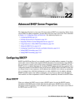
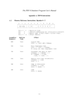
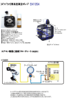
The procedure for linking Controls:
1.
Connect the RS-232 from the host to the 86MM Controls as shown.
HOST
23
CONTROL
COMPUTER
3
#1
2
71
CONTROL
3
#2
2
1
CONTROL
3
#3
2
1
3 OTHER CONTROLS
to #255
2
1
2.
Set RS-232 parameters on the host and Controls the same.
3.
Initialize Controls by sending the following.
EZT
The "E" commands all the Controls ON-LINE. The "Z" Zeros the Absolute Position
Registers that would have accumulated steps if the Controls were run in the JOG/SLEW
mode. The "T" Toggle the echo off preventing unwanted replication of information to each
Control.
4.
Use brackets to address each Control.
17
TROUBLESHOOTING PROCEDURE
SYMPTOM
POSSIBLE CAUSE
CORRECTIVE ACTION
JOG/SLEW light does
not "light" when Control
is switched "on".
Blown fuse.
Motor does not operate.
Limit switch(es)
closed position.
in
Check limit switches for proper
action, or try without cables
attached.
Control does not come
ON-LINE when sent
"E".
RS-232C may not be
connected properly.
Trace Transmitted Data, Received
Data, and Signal Ground wires from
your computer to the 86MM
Control.
Your
computer
or
terminal is not sending
upper case letters.
Transmit only upper case letters.
The Control will not respond to
lower case.
Your computer may
require a high on its
Data Set Ready (DSR)
line. The 86MM does
not implement the RS232C control lines.
Check
with
the
computer
manufacturer to see if the DSR line
must be artificially pulled high, or if
it can be disabled in software.
Control does not co
"ON-LINE" when sent
"E" or downloaded program does not operate
correctly.
The
RS-232C
parameters not set
properly.
Match the RS-232C settings on the
86MM to those of your computer or
terminal.
Your computer does
not receive data from
the Control.
Your computer may
require a "high" on its
Request To Send
(RTS) line.
Check
with
the
computer
manufacturer to see if the RTS line
must be artificially pulled high, or if
it can be disabled in software.
Motor does not run
when sent commands
to index.
STEPS/SEC
or
ACCEL/DECEL
settings out of range.
Set
STEPS/SEC
and
ACCEL/DECEL to specified values.
Motor stalls, it does not
move at all.
Inertia in system too
high, or mechanism
has seized.
Hand operate the system to locate
any binding. A larger motor, or a
different ratio in the mechanism
may be required.
Motor
stalls,
rotating slightly.
Acceleration too high.
Use a lower ACCEL/DECEL. Use
400 step/rev mode.
Motor cannot overcome
friction or load.
Check mechanism for ease of
movement. A larger motor may be
required, or your load will have to
be reduced or counterbalanced.
after
Check fuse located on back of
Control.
18
Motor stalls before
reaching
maximum
velocity.
Motor
torque
decreases as its velocity
in-creases.
Reduce STEPS/SEC setting of
motor.
With Motor remov-ed
from equipment, Motor
runs errat-ically at all
speeds, has no torque.
Broken motor cable.
Check cable and connector for
broken wires and repair breaks.
Faulty Motor.
Replace Motor.
Damaged
transistor(s.)
Motor
or
resonates
loudly).
system
(vibrates
drive
Ship Control back for motor drive
repair to
Velmex, Inc.
Repair Dept.
Rt. 5 & 20
E. Bloomfield, NY 14443 or
replace TIP 122 transis-tors on
inside back panel.
The motor velocity is
the motor or system's
natural resonant frequency.
This
is
common at speeds
below 230 in the 200
step/rev mode.
Increase or decrease speed to
avoid resonance points. A damper
or flywheel added to the motor shaft
or lead screw may dampen the
resonance.
Program is lost every
time Control is turned
OFF (LEDs flash and
buzzer beeps when
Control is turned ON).
Control is not ON long
enough to charge
batteries.
See page 11, MEMORY/ BATTERY
RETENTION
for
charge
requirements.
Batteries have reached
their useful life (>1000
charge/discharge
cycles, or 4-6 yrs).
Replace batteries. See page 19,
BATTERIES for replace-ment
procedures.
Control stops operating
for no apparent reason.
Inductive surge on AC
power-line.
Isolate or remove any equipment
that may be putting "spikes" on the
power-line.
Inductive/Static surges
coming in the I/O connections.
Use 400 step/rev mode.
Make sure all external equipment
connected is properly grounded
and inductive loads are isolated
from Control.
19
HARDWARE
LIMIT SWITCHES
Limit switches are included on most UniSlide assemblies. The 86MM cable with the 7 pin Amphenol
connector plugs into these limit switches. The limit switch inputs are active-low (normally high by a 1K
ohm resistor connected to +5V).
The Positive limit is activated by a switch closure between pin E (Signal Gnd) and D (+ Limit). When
activated, motion in the positive direction (Motor rotating CW, Slider moves away from motor) is
terminated and the Control will proceed to the next command in the program.
The Negative limit is activated by a switch closure between pin B (Signal Gnd) and A (- Limit).
CABLES
Caution:
It is not recommended that the motor cable be extended or altered in any other way. If motor cable must
be extended the proper wire size should be used to prevent voltage drop. For motor cables to 15 feet use
#16 wire. For motor cables to 30 feet use #14 wire. For motor cables to 45 feet use #12 wire.
Motor and limit switch cables should not be put in a common conduit with other wiring.
If cables must be near inductive loads (transformers, motors, etc.) or near high energy sources, shielding
of the cables may be required.
RS-232 cables should be limited to a maximum of 20 feet. However, with special EIA cable 50 feet is
possible.
BATTERIES
Batteries do not require servicing, they have an estimated life of greater than 1000 charge/discharge
cycles or 4 to 6 years.
To replace batteries:
1. Unplug Control from AC power.
2. Remove screws (hex nuts) at each corner of the rear panel.
3. Tilt rear panel back.
4. Pull cover rearward and up to remove.
5. Slide battery retaining clips off batteries.
6. Replace batteries following polarity markings.
Caution:
Replacement batteries should have the following characteristics:
Three 1800 mAH, High Temperature Nickel Cadmium "C" Size, 180 mA charge rating ( SANYO Model
No. KR-CH, or SAFT Model No. 2.0PT ).
The following batteries can be substituted, but not being high- temperature type, useful life may be
reduced.
Radio Shack Cat. No. 23-141, or Cat. No. 23-124.
The No. 23-124 batteries have 1100 mAH capacity, reducing program retention to 2 weeks.
20
SPECIFICATIONS
FUNCTIONAL
A complete microcomputer-based Controller/Driver for stepping motor control.
Interactive limit switch inputs (TTL) for CW and CCW direction.
One User Input (TTL), and one User Output (0 or +5V, 10 ma sinking capability).
Programming through full-duplex RS-232C port (300 to 7200 Baud settable, 7 Data bits, Even parity, 2
Stop bits, ASCII) or from a 16-key front panel keyboard.
User available RAM for program storage is 101 bytes, 27 bytes with battery back-up.
Motor is manually controllable at the front panel.
JOG/SLEW, ACCEL/DECEL, STEPS/SEC, PAUSE/OUTPUT, USER I/O, INDEX, and LOOP menu
LEDs for input selection.
CLEAR, Run, M, -, | , | , Ent, and 0 to 9 buttons at the front panel.
Remote Run and Reset input (TTL) connection at the front panel.
Six foot motor and limit switch cables with connectors
MOTOR COMPATIBILITY
For use with 1.8o Permanent Magnet stepper motors, 5 amp/phase max.
The 86MM Control is factory adjusted for a particular motor current.
PHYSICAL
Weight:
19.5 lbs.
Height:
8.5 inches
Width:
11.2 inches
Depth:
14.0 inches
ELECTRICAL REQUIREMENTS
120VAC 60Hz, 350 watts
ENVIRONMENTAL
32o to 120o F
Convection cooling
21