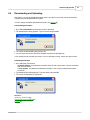
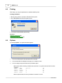
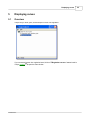
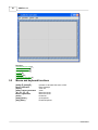
1
VISUPC
0.12
User Manual
© 2004 Autinor
Revision : 24/03/2004
VISUPC 0.12
© 2004 Autinor
All rights reserved. No parts of this work may be reproduced in any form or by any means - graphic, electronic, or
mechanical, including photocopying, recording, taping, or information storage and retrieval systems - without the written
permission of the publisher.
Products that are referred to in this document may be either trademarks and/or registered trademarks of the respective
owners. The publisher and the author make no claim to these trademarks.
While every precaution has been taken in the preparation of this document, the publisher and the author assume no
responsibility for errors or omissions, or for damages resulting from the use of information contained in this document
or from the use of programs and source code that may accompany it. In no event shall the publisher and the author be
liable for any loss of profit or any other commercial damage caused or alleged to have been caused directly or indirectly
by this document.
Printed: mars 2004 in France
Contents
I
Table of Contents
Foreword
0
Part I Introduction
1 Welcome
4
................................................................................................................................... 4
2 What's new ................................................................................................................................... 6
3 Registering Visupc
...................................................................................................................................
for modem use
6
Part II Visupc Explorer
1 Overview
9
................................................................................................................................... 9
2 Connecting ................................................................................................................................... 9
3 Exploring
................................................................................................................................... 10
4 Desktop saving
................................................................................................................................... 11
5 Options
................................................................................................................................... 12
6 Phone book ................................................................................................................................... 13
15
Part III Properties
1 Overview
................................................................................................................................... 15
Part IV Advanced properties
1 Overview
18
................................................................................................................................... 18
2 Mouse and keyboard
...................................................................................................................................
functions
20
3 Modifying parameters
................................................................................................................................... 20
4 Downloading...................................................................................................................................
and Uploading
21
5 Printing
................................................................................................................................... 22
6 Options
................................................................................................................................... 22
Part V Displaying curves
1 Overview
25
................................................................................................................................... 25
2 Mouse and keyboard
...................................................................................................................................
functions
26
3 Downloading...................................................................................................................................
curves
27
Setting downloading
..........................................................................................................................................................
parameters
27
Downloading
.......................................................................................................................................................... 27
Multiple downloads
.......................................................................................................................................................... 28
Automatic download
.......................................................................................................................................................... 28
4 Using the chart
...................................................................................................................................
window
28
Showing the coordinates
.......................................................................................................................................................... 28
Zooming the chart
.......................................................................................................................................................... 29
Mooving the chart
.......................................................................................................................................................... 29
Printing
.......................................................................................................................................................... 29
Exporting
.......................................................................................................................................................... 29
© 2004 Autinor
I
II
VISUPC 0.12
Export to bitmap
.........................................................................................................................................................
file
30
Export using.........................................................................................................................................................
the clipboard
30
Comparing charts
.......................................................................................................................................................... 30
Changing the Axis
.......................................................................................................................................................... 30
5 Options
................................................................................................................................... 31
Chart
.......................................................................................................................................................... 31
Path setting
.......................................................................................................................................................... 31
Part VI Supervisor
1 Overview
33
................................................................................................................................... 33
2 Control panel
...................................................................................................................................
with P314
35
3 Control panel
...................................................................................................................................
with modem
36
4 Control panel
...................................................................................................................................
on Legend Horizontal & Vertical bus
37
Part VII Connecting modem to equipment
39
1 Special cable...................................................................................................................................
for 32 &191 series (SP1)
39
2 Special cable...................................................................................................................................
for P313 (SP2)
40
3 Modem setting
................................................................................................................................... 40
4 Unlocking parameters
................................................................................................................................... 43
Part VIII FAQ : Frequently asked questions
46
1 Translating Visupc
................................................................................................................................... 46
2 Using an USB/RS232
...................................................................................................................................
adaptor
46
3 Special cable...................................................................................................................................
for N10 or BG21 connection
47
4 How to change
...................................................................................................................................
the Visupc language ?
47
5 How to increase
...................................................................................................................................
Visupc connection ?
47
Index
0
© 2004 Autinor
Part
I
4
VISUPC 0.12
1
Introduction
1.1
Welcome
Visupc is an universal tool to program, check, analysis of Autinor electronic systems.
It works under Windows 98,2000,XP.
Your computer must have an serial RS232 port or a modem inside. You can use an USB-RS232
adaptor (see USB/RS232 adaptor in FAQ) 46
Visupc must be used by a competent technician.
AUTINOR SHALL NOT BE LIABLE FOR ANY DAMAGE IN ANY WAY OF USE THIS SOFTWARE.
When you run Visupc, the explorer presents all connected system and tools :
Use the explorer
9
and choose (depend of systems) :
· See a list of variables and parameters and change them 18
© 2004 Autinor
Introduction
· Draw charts of lift move 25
· See a set of lifts 33
© 2004 Autinor
5
6
1.2
VISUPC 0.12
What's new
The full history of the sofware can be found in the Version.txt file in the application directory.
See this file
1.3
Registering Visupc for modem use
If you have purchased the modem version of Visupc, you need activate this function :
1.
Go to Help | About. This window appear :
2.
Note the serial number written at the left bottom corner (560DFD52 in this picture) and call Autinor
or e-mail.
You will receive a new number. Overwrite the old one by the new one.
3.
© 2004 Autinor
Introduction
4.
Press OK and start again Visupc. Now you can choose a modem device in the explorer.
Note :
The serial number depends of you PC. If you install Visupc in 2 PC you need 2 serial numbers.
© 2004 Autinor
7
Part
II
Visupc Explorer
2
Visupc Explorer
2.1
Overview
9
Visupc Explorer is the main window of Visupc and you see it when you run Visupc.
With this window, you can :
Connect your PC to an electronic system 9
Navigate between different connected system, open and close specific windows 10
like :
· Properties 15
· Advanced properties 18
· Charts 25
· Lifts supervisor 33
You can also :
Save the desktop settings 11
Modify Visupc options 12
2.2
Connecting
1.
Connect your PC to the equipment.
In most of case you need the P313 isolation interface. Connect it between computer and system.
If you want to connect computer to N10 or BG21 board you need a special cable : see
Special cable for N10 or BG21 connection 47
If you have purchased the Modem version, you can also use an internal or external modem to
establish the connection. The specific modem driver must be installed. (see
Registering Visupc for modem use 6 )
You can also connect your computer on Legend CAN bus (with an interface) or on Autinor RS485
bus (with P314 interface). See Supervisor 33 .
2.
© 2004 Autinor
Run Visupc. You see this window :
10
VISUPC 0.12
3.
4.
5.
Choose the COM port connected to the equipment or choose your modem.
Press Start button
If you select a modem device, a phone number is asked :
Type your phone number and press OK
If you want call a DVT, type "DVT:" at the beginning of the phone number (DVT:0320625600 for
example )
6.
Now, Visupc is looking for connected system and after show a tree view with all found systems as
nodes and special windows.
See Exploring 10
2.3
Exploring
When Visupc is connected, it show an tree view with all connected systems and specifics windows :
© 2004 Autinor
Visupc Explorer
11
In this example, Visupc has found and AC01 board (Legend machine-room board) and an AC04
board (car-top board).
All found systems have a child check box to open or close special window like :
Properties 15
Advanced properties 18
Regulation move charts 25
Supervisor 4
These windows depend of the connected nodes.
Check the box to open the window, uncheck to close it.
Note : With protected nodes (like Teleport system), Visupc asks a password. Type it and press OK.
With Teleport, the code is the value written in CODTEL parameter (local connection) or CODIST
parameter (modem connection)
If you have many opened windows, you can press [Ctrl]+[Tab] to switch between windows.
2.4
Desktop saving
You can save the desktop and reload it automatically when the same system is connected.
For example, each time you connect your PC to a regulation system, you want to open the advanced
proprerties window and the chart windows.
Do this :
1.
2.
3.
© 2004 Autinor
Connect your PC to the system, run Visupc and press Start button
When your PC is connected, open the advanced properties and chart window by checking the
box in Visupc explorer
Move and resize the windows as you like
12
VISUPC 0.12
4.
Go to File | Save Desktop. The screen setting is saved
Now when you connect Visupc to an regulation system, the windows appear automatically.
2.5
Options
Go to File | Options in Visupc explorer. This window appears :
You can change these values :
Modem attempt
When the modem can't connect, it retry the call without user manipulation. The number of calls are
limited by this value. (See Modem delay)
Modem Delay
When the modem can't connect, it wait during this value and retry the call. (See Modem Attempt)
Device
Select the default device when Visupc starts.
Do before dial
You can write prefix phone number added when Visupc dials.
þ Always show Explorer
If not checked, Visupc explorer is reduced when you open a node window.
þ Save password
Some systems are password protected. If checked, the last password is memorized and use when
needed.
þ Use phone book
When checked, you can associate phone numbers to an identification string. See Phone list 13
© 2004 Autinor
Visupc Explorer
2.6
13
Phone book
If þ Use phone book in Options 12 is checked, you can associate phone numbers to identification
string :
To add a phone number
1.
2.
Run Visupc, choose a modem device and press Start
A phone number is asked
3.
4.
Press OK
This window appears :
5.
6.
Type your identification string and press OK
Now your phone number is stored in the phone book
To find a phone number in the phone book
Next time you want call this number :
1.
Click on the down Arrow button to see the phone book :
2.
Select your identification and press OK
Note
Phone book is stored in the PhoneBook.ini file.
© 2004 Autinor
Part
III
Properties
3
Properties
3.1
Overview
Properties windows are easy parametering forms.
Most important parameters and variables are grouped by function.
Some special parameters can only be modified in the Properties window 18 .
Use to Properties window 18 to print and save parameters files.
These windows depend of the connected system and parameters are not explain in this
documentation (see system parameters documentation).
In the Visupc explorer
9
, check the þ Properties of the wanted node.
The properties window appears :
© 2004 Autinor
15
16
VISUPC 0.12
example : French MAT properties window
This window is tiled into 4 areas :
· Title bar with status icon : when the circular icon is red, parameters can't be modified (lift in
move for example)
· Parametering area (see bellow)
· Bottom right fault panel : Display the current fault number and code
· Bottom left connection icon : this icon is animated when connection is running.
Parameters area
These standard rules depend of systems.
· White controls can be modified (parameters),
· Colored controls are read only (variables),
· When a check box is changed, the new value is automatically send to the system
· When an edit box is changed, the value is sent when you press [Enter] key or when you change the
focus.
· Each controls is disable after change during system updating.
· You can move the mouse on a control and wait : a help sentence appears.
© 2004 Autinor
Part
IV
18
VISUPC 0.12
4
Advanced properties
4.1
Overview
In the Visupc explorer
9
, check the þ Advanced properties of the wanted node.
The properties window appears :
© 2004 Autinor
Advanced properties
19
This window is tiled into 4 areas :
· Blue left panel : this panel show the system variables (the values can't be modified)
· Gray right panel : this panel show the parameters (read-write values, except read only
parameters)
· Bottom right fault panel : Display the current fault number and code
· Bottom left connection icon : this icon is animated when connection is running.
You can hide some panels with Window command in the menu
Note that special systems can show more than one parameter or variable panel.
Each parameter/variable line as 4 columns :
· Address : address of the variable in system (can't be modified)
· Name : name of the variable (can't be modified). You can move the mouse on the name and wait
: a help sentence appears.
· Value : value of the variable (can be modified except read only values)
· Type : display base and length of the variable (can't be modified)
Binary variables and parameters
Binary variables can be detailed if the first character of the name is '+'.
Double click on the name. Lines with options are added in fuchsias color.
Double click again on the name to mask options.
You can also use [Alt]+[ê] to detail options or [Alt]+[é] to mask options.
You can detail all binary variables with Window | Expand command or mask all binary options with
Window | Collapse command.
See also :
© 2004 Autinor
20
VISUPC 0.12
Modifying parameters 20
Downloading and Uploading 21
Printing 22
4.2
Mouse and keyboard functions
[Tab] :
Change active variables panel
[é], [ê] :
Change the select variables
[PgUp], [PgDn] :
Previous / next page
[Enter] :
Apply new variable value
[Ctrl]+F
Open the search window
[Alt]+[Enter]
Expand or collapse binary variable. This is automatically done when the
cursor is on binary variable during one more 1 second.
4.3
Modifying parameters
You can change the value of parameters in the parameter panel, except read only parameters :
· Use the [Tab] key to select the wanted panel.
· Use then [é] or [ê] to select the parameter line. You can also use [PgUp] or [PgDn] key to go to
next/previous page.
· Type the value you want without units
· Press [Enter]. If Visupc stay in edit mode, the value you have written is not good. Type something
else.
· The value is send to system, and the read back value is displayed. (This value can be different if the
value written is not allowed).
Note : binary options
When the select line is on a binary variable, wait for 1 second. The options are automatically detailed.
When you quit the variable, the options are grouped again. You can also press [Alt] [Enter] to expand
or collapse these kind of variables.
You can localize variable and parameters with the find function :
· Click on Find command on the menu. This window appears :
· Type the parameter name (or the beginning of the name), or the address (must begin with an
decimal value '0' to '9'. For example, type 0FF08 to search the FF08 address).
· Press [OK]
· Visupc search the variable in parameters panel and variables panel and highlight it.
See also :
Downloading and Uploading 21
Printing 22
© 2004 Autinor
Advanced properties
4.4
21
Downloading and Uploading
With Visupc, you can download parameters values, save them in a text file (can be opened with
notepad), and upload parameters to system.
You can change the default parameters files path, see Options 22
Downloading parameters
· Go to File | Download and choose the panel to download
· The standard save dialog appears. Type the name and press OK
· The values are downloading and saving to file.
· You can open and see this file with a standard text editor like Notepad.exe
If you change the file manually, be careful. If you do something wrong, Visupc can't open the file.
Uploading parameters
· Go to File menu and choose
Complete Upload : all parameters are written even the value is the same. Use this command
with local connection
or Fast Upload : only different parameters are written. This is a good method with modem
connection.
· The standard open dialog appears. Type the name and press OK
· The values are uploading to equipment.
See also :
Modifying parameters 20
Downloading and Uploading 21
Printing 22
© 2004 Autinor
22
4.5
VISUPC 0.12
Printing
With Visupc, you can print parameters on windows default printer :
Printing parameters
· Be sure that a printer is selected in Windows Printer panel.
· Go to File | Print and choose the panel to print
· The values are downloading and printing
See also :
Modifying parameters 20
Downloading and Uploading 21
4.6
Options
Go to File | Options. This options window appears :
1.
You can modify the path were parameters file are saved
2.
You can deactivate the background image if you computer is slow.
3.
You can change the print and save binary variables option :
- With options detail, the binary variables are saved twice : the global value and the bit values
Example :
0F80B
0F80B.0
0F80B.1
0F80B.2
0F80B.5
|-HARD
| SIMUL
| AP_DIR
| VALMOT
| PVISO
|00000101
|1
|0
|1
|0
|B8
|B1
|B1
|B1
|B1
- With not options detail, the binary variables are saved in one line.
© 2004 Autinor
Advanced properties
Example
0F80B
© 2004 Autinor
|+HARD
|VALMOT SIMUL
|B8
23
Part
V
Displaying curves
5
Displaying curves
5.1
Overview
Visupc lets you show, print, save and export curves of lift regulation.
If you connected system is a regulation board, click on þ Regulation curves of wanted node in
Visupc explorer 9 to open the chart window :
© 2004 Autinor
25
26
VISUPC 0.12
See also :
Downloading curves 27
Zooming the chart 29
Changing the Axis 30
Printing 29
Exporting 29
Personalize the chart 31
5.2
Mouse and keyboard functions
[Shift][ê], [Shift][é] :
Mouse left button :
[Space] :
[Shift] + Mouse left button:
[è], [ç], [é], [ê] :
Mouse right button :
[Enter] :
[Shift]+[Enter] :
[Alt]+[Enter] :
Increase or decrease the zoom to 20%.
Draw rectangle
Zoom out
Zoom
Move the curves
Move the curves
Download
Chart options
Download options
© 2004 Autinor
Displaying curves
5.3
Downloading curves
5.3.1
Setting downloading parameters
27
When downloading data, Autinor regulation systems are sending the values of the 4 variables written
in Visu1..Visu4 parameters.
These parameters are memorized in a permanent memory inside the electronic system and can be
selected by this procedure :
1. Choose Options | Download. This window appear :
2.
3.
Choose the variable for each Visu parameter
Press OK
See also :
Downloading 27
Multiple downloads 28
Automatic download 28
5.3.2
Downloading
To enter in download mode :
1. Click on Download or press [Enter]. This window appear :
© 2004 Autinor
28
VISUPC 0.12
2.
3.
4.
Visupc is waiting for data sent by the equipment when lift is moving.
Move the lift. The download window preview the curves.
When lift stops, visupc quit the download mode and the curves appear in the main window.
See also :
Setting downloading parameters 27
Multiple downloads 28
Automatic download 28
5.3.3
Multiple downloads
If the þ Multiple download box is checked, the download mode is maintained after lift stop.
With this option, it is possible to capture and show many curves at the same time.
Click on Cancel button to leave the download mode and show the curves.
See also :
Downloading 27
Setting downloading parameters 27
Automatic download 28
5.3.4
Automatic download
If Automatic Download is checked in the Options menu, download start automatically at the
beginning of the lift move without key pressing.
Note :
If this menu item is not visible, this command is not possible with the connected board.
See also :
Downloading 27
Setting downloading parameters 27
Multiple downloads 28
5.4
Using the chart window
5.4.1
Showing the coordinates
When the mouse is moving on the chart, the status bar shows the mouse coordinates :
© 2004 Autinor
Displaying curves
29
To know the distance separating two points from a curve, trace a rectangle delimited by these two
points:
1.
2.
Click on the first point and maintain the mouse button pressed
Move the mouse to the second point and release the mouse button
The status bar now indicates the horizontal and vertical distances between the two points
5.4.2
Zooming the chart
Using the mouse
Draw the region rectangle to zoom with the [Shift] key pressed :
1. Press [Shift]
2. Click at the top left corner of the region and keep the left mouse button pressed
3. Move the mouse to the bottom right corner and release the mouse button
4. Release [Shift] key
Using the keyboard
Use [Shift][ê] or [Shift][é] to increase or decrease the zoom to 20%.
Note
Press [Space] or zoom from right to left to obtain the full chart.
See also:
Moving the chart 29
5.4.3
Mooving the chart
The charts can be moved using the [è], [ç], [é], [ê] keys or using the mouse right button.
See also:
Zooming the chart 29
5.4.4
Printing
1.
2.
If you want print a title, click Option | Chart and fill the Title box in the options window.
Click File | Print to print the visible area of the graph.
The paper orientation is forced to landscape and the graph is adjust to the paper full size.
If you want change the style of printed paper, export the graph picture to picture editor, customize and
print it.
See also :
Export 29
How to zoom the chart 29
How to move the chart 29
5.4.5
Exporting
If you have to build reports with chart of lifts move, you can export them to another software:
© 2004 Autinor
30
VISUPC 0.12
· Export using a bitmap file 30
· Export using the clipboard 30
5.4.5.1
Export to bitmap file
You can export the chart to a bitmap file with current zoom and position :
1. Click File | Save as bitmap
2. Select the directory, type the file name and press OK
See also :
How to zoom the chart 29
How to move the chart 29
5.4.5.2
Export using the clipboard
You can export the chart to the windows clipboard with current zoom and position : use the File |
Copy command.
See also :
How to zoom the chart 29
How to move the chart 29
5.4.6
Comparing charts
With Visupc you can compare some curves with different set of parameters :
1. Do an capture
2. Save the chart with File | Save command
3.
Change the parameters you want with the Advanced properties 18 window or Properties 15
window.
4.
5.
Do an capture with new parameters
Add the chart with old parameters to the current chart with the File | Add file command
Note :
When you save a graph, only the downloaded curves are saved, not the curves added with the Add
File command.
5.4.7
Changing the Axis
You can select the visible axis in the chart with the Options | Axis command.
Note :
When you select an axis, the other axis are hidden and resize by muliplicate by a 10-exposanted
value to align the curves.
For example :
4 Hz = 400 V = 40 A
© 2004 Autinor
Displaying curves
5.5
Options
5.5.1
Chart
Go to Options | Chart to open the Charts tab in the Options window :
With this window you can change for each curve :
Color : click on [...] button to open the color dialog
Width : click on the arrow buttons
þ Visible : change the visibility with this box.
You can change the chart options :
Title : type the title of the chart
þ Animated Zoom : Enable the option and zoom the graph. It's nice, isn't it ?
Chart XY : press this button to add an X-Y curve :
Choose the X and the Y Value and press OK
5.5.2
Path setting
You can change the path for saving and loading charts :
Go to Options | Charts, choose the Other tab, change the path and press OK.
© 2004 Autinor
31
Part
VI
Supervisor
6
Supervisor
6.1
Overview
33
The lift supervisor shows a picture of one or more lifts.
It is available with 191 and 32 series, direct connection or trough MAT1S, MADAS or P314 bus.
It is also available on Legend horizontal & vertical bus (with AC03/PcCan board as interface).
Note that you can't open the Supervisor and the PcCan properties window at the same time.
In the Visupc explorer
9
, check the þ Lift supervisor of the wanted node.
In this example, you can show the Supervisor from Teleport (see all lifts) or from one lift (see only this
lift).
If a password is asked, type it. With Teleport, the code is the value written in CODTEL parameter
(local connection) or CODIST parameter (modem connection).
A supervisor window appears :
© 2004 Autinor
34
VISUPC 0.12
Control panel
The control panel is at the left of the window and depends of connection type :
Control panel with P314 35
Control panel with modem 36
Control panel on Legend Horizontal bus 37
Actions to lifts
The picture of lifts presents :
: landing up calls
: landing down calls
: car calls
Click on these button to send calls.
With 191 & 32 series, only car calls are possible.
With Legend, only landing calls are possible (at this time)
The levels are always numbered from 0 to last level -1.
© 2004 Autinor
Supervisor
6.2
Control panel with P314
This panel is shown with P314 bus connection.
This bus is a RS485 bus and can group up to 47 lifts. It is usually used for lifts local monitoring.
It is also use with concentrator / mada connection.
The panel is at the left of the supervisor window :
It shows :
The data rate of the bus. A value less than 95% is bad (bad bus
connection : check connections and dip settings)
The Interfaces grid shows all founded node and there status :
ok in green, error in red (Bus conflicts)
Trames / Sec box shows the frame rate.
With the control panel, you can activate advanced options :
þ Levels in fire
When checked, a column is added in each multiplex and show the fire mode :
level in fire
normal mode
þ Start counter
When checked, a line is added below each lift to display the start counter
þ E/S P314
When checked, 4 lines is added below each lift to see P314 inputs and control output
customerized relays
© 2004 Autinor
35
36
VISUPC 0.12
Click on Rel1 or Rel2 to change the relays status. When activated, Rel1
(Rel2) is written in red color.
When the inputs are actives, In1 (In2) is written in red.
6.3
Control panel with modem
This panel is shown with modem connection.
The panel is at the left of the supervisor window :
Trames / Sec shows the frame rate.
With the control panel, you can activate advanced options :
þ Levels in fire
When checked, a column is added in each multiplex and show the fire mode :
level in fire
normal mode
þ Start counter
When checked, a line is added below each lift to display the start counter
© 2004 Autinor
Supervisor
6.4
37
Control panel on Legend Horizontal & Vertical bus
This panel is shown with Legend horizontal or vertical bus connection. On vertical bus, only one lift
appears.
Important note :
You need a AC03 board with special firmware (PCCAN2) and special parameters (PCCAN2.PAR in
the program directory) to interface can bus to RS232 PC plug.
With the control panel, you can activate then þ Mask option :
When checked, the multiplex masks are drawn in the lift picture.
n : Up and Down authorized calls (fuchsias)
n : Up authorized calls (green)
n : Down authorized calls (blue)
© 2004 Autinor
Part
VII
Connecting modem to equipment
7
39
Connecting modem to equipment
You can connect a modem to all Autinor electronic systems without teleport system.
With 32, 191 series, you need :
· A BG21 board (if not included in the main board)
· A Special cable for 32 &191 series 39
· A modem with special Setting 40
With electronic systems used with P313 isolation interface (AC01,AC04,AC05, VEC01, ...), you
need:
· A standard isolated P313 interface
· A Special cable for P313 40
· A modem with special Setting 40
Parameter writes protection
With 32 & 101 series and motor regulation, the write command has not error detection. If an error
occur when you want change a parameter, another parameter may be accidentally modified.
Normally, Visupc is near the lift and you can see what's happening, change errors and test the lift.
With modem connections, you are far to the lift and you cannot control what you do. In this case, all
parameters are write protected with distant connection.
If you want (but don't do this), you can change the access for chosen parameters but be sure that :
· Write access to unlocked parameters is not dangerous for lift's users
· People who use Visupc is competent technician and check all parameters before the end of
connection.
Autinor shall not be liable for any damage in any way if you unlock
write protection.
To change write protection, see Unlocking parameters 43
Note :
With Legend system, write command is error protected by a check-sum byte.
In Teleport system, parameters can be changed.
7.1
Special cable for 32 &191 series (SP1)
Use a cable with this wiring diagram for connecting a lift to the Modem.
© 2004 Autinor
40
VISUPC 0.12
(Pin 2 connected to Pin 2, 3 to 3)
THIS CABLE IS NOT THE SAME AS THE P313 MODEM CABLE
This cable must be placed between modem and equipment :
[Equipment] ó [BG21] ó [Special cable] ó [modem] ó [Phone line]
See also :
Modem setting 40
7.2
Special cable for P313 (SP2)
Use a cable with this wiring diagram for connecting the P313 interface (Legend, MLIFT, ...)
to the Modem.
(Pin 2 connected to Pin 3)
THIS CABLE IS NOT THE SAME AS THE 32 & 191 SERIES MODEM CABLE
This cable must be placed between modem and P313 :
[Equipment] ó [DB9M/DB25F adapter] ó [P313] ó [DB25M/DB9F adapter] ó [Special cable] ó
[modem] ó [Phone line]
See also :
Modem setting 40
7.3
Modem setting
The modem must be configured for hang up and connect alone.
This setting is made by sending standard Hayes commands to modem with a terminal software (for
example Hyper terminal in Windows)
This works with Olitec Self Memory modem and should work with all modems Hayes command
compliant.
Modem setting
© 2004 Autinor
Connecting modem to equipment
1.
2.
3.
4.
5.
6.
7.
41
Connect the PC to the equipment WITHOUT modem. Run Visupc, wait for connection and check
the datarate in the status bar of Visupc explorer window.
(9600 in this example)
Close Visupc, connect the modem to the PC with standard modem cable and run Hyper terminal
software installed by Windows.
Type a name for the connection (for example : Modem) and press OK
In the next window choose the COM port connected to the modem (COM1 for example). Do NOT
choose the modem device. Press OK
In the next window, type the data rate found at 1 and fill the other parameters like this : (Aucun =
None)
Press OK. Now you can send commands to the modem
Type AT&F and press [Enter] (this command restore factory configuration). The modem answers
OK
8. Type AT&S0=2 and press [Enter] (this command set the modem in auto-answer mode and hang
up after 2 rings). The modem answers OK
9. Type AT&W0 and press [Enter] (Store the parameters in profile 0). The modem answers OK
10. Type AT&Y0 and press [Enter] (Set profile 0 as default reset profile). The modem answers OK
11. Reset the modem
12. Type AT&V (display current configuration) and press OK. The Hyper terminal window must be
something like this :
© 2004 Autinor
42
VISUPC 0.12
13. Check in the result of AT&V command that S00 is not null.
Modem testing
If your PC has an integrated modem or another COM port connected to another modem, you can
check the modem settings :
1.
2.
3.
4.
Connect the modem under test to the PC and run Hyper Terminal as described on top.
Connect 2 phone lines to the 2 modems
With Visupc, calls the modem under test.
If the modem sends RING, RING, CONNECT XXXXX (xxxxx is the connection speed), it works
© 2004 Autinor
Connecting modem to equipment
43
Hyper Terminal screen copy with working modem
If your modem doesn't work, try another modem type or sent to Autinor the result of AT&V command.
See also :
Special cable for 32 &191 series 39
Special cable for P313 40
data rate
7.4
Unlocking parameters
With 32 & 101 series and motor regulation, the write command has not error detection. If an error
occur when you want change a parameter, another parameter may be accidentally modified.
Normally, Visupc is near the lift and you can see what's happening, change errors and test the lift.
With modem connections, you are far to the lift and you cannot control what you do. In this case, all
parameters are write protected with distant connection.
If you want (but don't do this), you can change the acces for chosen parameters but be sure that :
· Write access to unlocked parameters is not dangerous for lift's users
· People who use Visupc is competent technician and check all parameters before the end of
connection.
Autinor shall not be liable for any damage in any way if you unlock
write protection.
To change write protection, do :
© 2004 Autinor
44
VISUPC 0.12
1.
2.
3.
4.
When connected to system (local or distant), go to Advanced properties 18 an go to File | Edit
system file
The equipment parameters file is opened by notepad.
Locate in [Variables] section the parameters you want to unlock and add < ,+MW > at the end of
the parameter line (without '<','>' and spaces but with ',')
Save the file and start again Visupc.
Note :
With Legend system, write command is error protected by a check-sum byte.
In Teleport system, parameters can be changed.
access
© 2004 Autinor
Part
VIII
46
VISUPC 0.12
8
FAQ : Frequently asked questions
8.1
Translating Visupc
It is very easy to translate Visupc in any language : each message displayed is stored into a text file.
The name of this file is Visupc and the extension is the windows region code.
When started, Visupc read this code and search for the Visupc translation file. If not found, it uses the
English Visupc.EN file, if not found it uses the French Visupc.VPC file.
To translate Visupc do :
1.
2.
3.
Go to File | Option menu and click on the blue rectangle at the top right corner of the Standard
tab. The rectangle show your region code.
Visupc open the translation file with the Notepad. If the file doesn't exist, it is created.
This file is a standard Ini file. You have to translate the sentences written after the '=' character in
all sections except [Fichiers] and [Visupc].
Some strings like '%s' or '%d' can by move but cannot be deleted. In run-time they are replaced
by a formatted string.
The '&' character is used to underline the next character (shortcut).
Save the file and start again Visupc.
If you want, you can also translate equipment parameters files. These files contain all parameters
definitions. There are stored in the Visupc directory (C:\Program Files\Autinor\Visupc) and have the
windows region code as extension.
To translate equipment files do :
1.
2.
Copy all equipment files in Visupc directory and rename them with your region code (see the blue
rectangle in the File | Options | Standard window).
Translate these files. They are standard Ini files. Translate [@.....] and [Captures] sections if
present, and [Visupc].Texte key.
Note :
Send to Autinor all translation files you have created or modify. They will be added in the install
software.
8.2
Using an USB/RS232 adaptor
If your computer don't have RS232 port, you can use an USB adaptor
1. Install completely the device (see manufacturer's documentation)
2. Open the P313 interface
3. Add 2 wires on the DB25 female PC connector :
· from pin 4 to 5
· from pin 6 to 20
© 2004 Autinor
FAQ : Frequently asked questions
8.3
47
Special cable for N10 or BG21 connection
If you want connect your PC to N10 or BG21 use a cable with this wiring diagram :
This cable must be placed between PC and equipment without P313 interface
[Equipment] ó [BG21] ó [Special cable] ó [Computer]
Note that this connection is not isolated.
If your computer is connected to ground you connect the equipment reference signal to earth trough
the cable and make an 01 fault.
When using this cable, use an notebook or isolation transformer.
8.4
How to change the Visupc language ?
When started, Visupc read the windows country code and use it to determine the user language.
You can change this and force Visupc to use another region code. To do this, you have to modify the
command line parameters in the visupc shortcut :
· Select the short cut properties
· On the link tab, add at the end of the command line : "/Country:xx" where xx is the wanted windows
region code :
FR : France
EN :English
CN : Chinese
DE : Deutschland
The region codes recognized by Visupc are the extensions of Visupc.* files in C:\Program
files\Autinor\Visupc for windows directory.
8.5
How to increase Visupc connection ?
If your always use the COM1 serial port on you computer, you can force the connection when Visupc
is started : you don't need to press Start button anymore.
To do this, you have to modify the command line parameters in the visupc shortcut :
· Select the short cut properties
· On the link tab, add at the end of the command line : "/Device:xx" where xx is the device
identification (this is the value written in the devices box on main window of Visupc). It can be a
modem name.
© 2004 Autinor