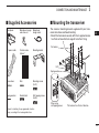
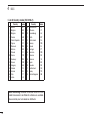
1
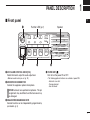
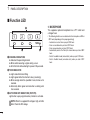
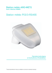
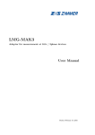
Limited functions only INSTRUCTION MANUAL VHF MOBILE TRANSCEIVER iF5012 IMPORTANT READ ALL INSTRUCTIONS EXPLICIT DEFINITIONS carefully and com- pletely before using the transceiver. SAVE THIS INSTRUCTION MANUAL — This instruction manual contains important operating instructions for the IC-F5012 VHF MOBILE TRANSCEIVER. WORD DEFINITION R WARNING! Personal injury, fire hazard or electric shock may occur. CAUTION NOTE Icom, Icom Inc. and the Icom logo are registered trademarks of Icom Incorporated (Japan) in Japan, the United States, the United Kingdom, Germany, France, Spain, Russia and/or other countries. All other products or brands are registered trademarks or trademarks of their respective holders. i Equipment damage may occur. If disregarded, inconvenience only. No risk of personal injury, fire or electric shock. PRECAUTIONS R WARNING! NEVER connect the transceiver to an DO NOT use or place the transceiver in areas with tem- R WARNING! NEVER connect the transceiver to a DO NOT operate the transceiver without running the ve- R WARNING! NEVER cut the DC power cable be- DO NOT place the transceiver in excessively dusty envi- AC outlet. This may pose a fire hazard or result in an electric shock. power source of more than 16 V DC or use reverse polarity. This could cause a fire or damage the transceiver. tween the DC plug and fuse holder. If an incorrect connection is made after cutting, the transceiver might be damaged. R WARNING! NEVER place the transceiver where normal operation of the vehicle may be hindered or where it could cause bodily injury. CAUTION: NEVER allow children to touch the transceiver. CAUTION: NEVER expose the transceiver to rain, peratures below –25°C or above +55°C, or in areas subject to direct sunlight, such as the dashboard. hicle’s engine. The vehicle’s battery will quickly run out when the transceiver transmits while the vehicle’s engine is OFF. ronments. DO NOT place the transceiver against walls. This will obstruct heat dissipation. DO NOT use harsh solvents such as benzine or alcohol when cleaning, as they will damage the transceiver surfaces. BE CAREFUL! The transceiver will become hot when operating continuously for long periods of time. snow or any liquids. USE the specified microphone only. Other microphones have different pin assignments and may damage the transceiver. Approved Icom optional equipment is designed for optimal performance when used with an Icom transceiver. Icom is not responsible for the destruction or damage to an Icom transceiver in the event the Icom transceiver is used with equipment that is not manufactured or approved by Icom. ii TABLE OF CONTENTS IMPORTANT........................................................................... i EXPLICIT DEFINITIONS........................................................ i PRECAUTIONS..................................................................... ii TABLE OF CONTENTS........................................................ iii 1 PANEL DESCRIPTION.................................................1–6 ■ Front panel....................................................................1 ■ Function LED................................................................2 ■ Programmable function keys.........................................3 2 BASIC OPERATION...................................................7–13 ■ Turning ON the power...................................................7 ■ Channel selection..........................................................7 ■ Call procedure...............................................................8 ■ Receiving and transmitting............................................8 ■ User Set mode............................................................10 ■ Scrambler function......................................................11 ■ Stun function...............................................................11 ■ Priority A channel selection.........................................11 ■ Emergency transmission.............................................12 ■ MDC 1200 system operation.......................................13 3 CONNECTION AND MAINTENANCE.....................14–16 ■ Rear panel connection................................................14 ■ Supplied Accessories..................................................15 ■ Mounting the transceiver.............................................15 ■ Antenna.......................................................................16 ■ Fuse replacement.......................................................16 ■ Cleaning......................................................................16 ■ Options........................................................................16 4 DOC..........................................................................17–18 iii PANEL DESCRIPTION 1 ■ Front panel Function LED (p. 2) q 1 2 3 Speaker 4 TX/RX P0 P1 w P2 e P3 r qAF VOLUME CONTROL KNOB [VOL] Rotate the knob to adjust the audio output level. rPOWER KEY [ ] Push to turn the power ON or OFF. • The following optional functions are available at power ON: - Automatic scan start - Password prompt - User Set mode • Minimum audio level is pre-set. (p. 10) wMICROPHONE CONNECTOR Connect the supplied or optional microphone. NEVER connect non-specified microphones. The pin assignments may be different and the transceiver may be damaged. 1 2 3 4 5 6 7 8 9 10 11 12 13 14 15 16 eDEALER-PROGRAMMABLE KEYS Desired functions can be independently programmed by your dealer. (p. 3) 1 1 PANEL DESCRIPTION ■ Function LED D MICROPHONE q 1 2 3 The supplied or optional microphone has a PTT switch and a hanger hook. 4 TX/RX e w qCHANNEL INDICATORS ➥ Indicates the operating channel. ➥ Blinks when receiving a signal during a scan. ➥ All LEDs blink while entering the power ON password. wTX/RX INDICATOR ➥ Lights red while transmitting. ➥ Lights green while the channel is busy (receiving). ➥ Blinks orange when the specified 2-tone, 5-tone call is received. ➥ Alternately blinks green and red when a cloning error has occurred. eACTIVATED KEY INDICATORS (P0/P1/P2) L ights when a pre-programmed key function is activated. 2 NOTE: When the supplied DC voltage is high, all LEDs blink. Check the DC voltage. • The following functions are available when the microphone is ON or OFF hook (depending on the preprogramming): - Automatic scan start when you put it ON hook. - Scan is cancelled when you take it OFF hook - Scan is paused when you take it OFF hook - Automatically selects the Priority A channel when you take it OFF hook. - Sets to ‘Inaudible’ mode (muted state) when you put it ON hook. - Sets to ‘Audible’ mode (unmuted state) when you take it OFF hook. PANEL DESCRIPTION ■ Programmable function keys The following functions can be assigned to [P0], [P1], [P2] and [P3] programmable function keys. Consult your Icom dealer or system operator for details concerning your transceivers programming. CH UP AND DOWN KEYS Push to select an operating channel. SCAN A START/STOP KEY Push to start or cancel a scan. SCAN B START/STOP KEY Push to start or cancel a scan. When a scan started with the Power ON Scan or by pushing this key, push to cancel it. If the scan is cancelled except by pushing this key, the cancelled scan resumes after the specified time period. SCAN ADD/DEL (TAG) KEY While scan is paused by a detected signal, on a channel other than a priority channel, push this key to clear the channel from the scan list. epending on the preprogramming, the cleared channel is D added to the scan list again after the scan is cancelled. 1 PRIO A/B KEYS ➥Push to select Priority Channel A or B. ➥To rewrite the operating channel as Priority A or Priority B, hold down [Prio A (Rewrite)] or [Prio B (Rewrite)] for 1 second. MR-CH 1/2/3/4 KEYS Push to directly select memory channels 1 to 4. MONI (AUDI) KEY ➥ Push to turn the CTCSS (DTCS) or 2/5-tone squelch Mute ON or OFF. • Only during LMR (Land Mobile Radio) operation, push to open any squelch, or deactivate any mute functions. • Only during PMR (Private Moble Radio) operation, push to activate one or two of the following functions on each channel (depending on the preprogramming): - Hold down to unmute the channel (‘Audible’ mode). - Push to mute the channel (‘Inaudible’ mode). - After the communication is finished, push to send a ‘reset code’ (only 5-tone operation). OTE: The ‘Audible’ (unmute) mode may automatically N return to the ‘Inaudible’ (mute) mode, after the pre-programmed time period. 1 2 3 4 5 6 7 8 9 10 11 12 13 14 15 16 ➥ Hold down this key for 1 second to cancel a scan, depending on the preprogramming. 3 1 PANEL DESCRIPTION ■ Programmable function keys (continued) LOCK KEY Hold down to electronically lock all programmable keys except the following: [Moni(Audi)], [Lock], [Call] (incl. Call A and Call B), [Emergency], [Surveillance], [Siren] and [Lone Worker]. DTMF AUTODIAL KEY Push to transmit a DTMF code. RE-DIAL KEY Push to transmit the last-transmitted DTMF code. • TX memories are cleared after turning OFF the transceiver. LONE WORKER KEY Push to turn the Lone Worker function ON or OFF. • If the Lone Worker function is turned ON, and no operation occurs during the pre-programming time period, the Emergency function is automatically turned ON. HIGH/LOW KEY Push to select the transmit output power temporarily or permanently, depending on the preprogramming. • Ask your dealer for the output power level for each selection. TALK AROUND KEY Push to turn the Talk Around function ON or OFF. • The Talk Around function equalizes the transmit frequency to the receive frequency for transceiver-to-transceiver communication. WIDE/NARROW KEY Push to toggle the IF bandwidth between wide and narrow. • The wide passband width can be selected from 25.0 or 20.0 kHz using the CS-F3020/F5010/F5020 cloning software. (PMR operation only) Ask your dealer for details. 4 CALL KEYS Push to transmit a 2/5-tone ID code. • Tone call transmission may be necessary before you call another station, depending on your signalling system. • [Call A] and/or [Call B] may be selectable when your system employs selective ‘Individual/Group’ calls. Ask your dealer which call is assigned to each key. EMERGENCY KEY Hold down for a specified period to transmit an emergency call. • If you want to cancel the emergency call, hold down the key again, before transmitting it. PANEL DESCRIPTION SURVEILLANCE KEY Push to turn the surveillance function ON or OFF. When this function is turned ON, the beeps do not sound the LED does not light when a signal is received or a key is pushed. SIREN Hold down for 1 second to sound the siren. This function can be used for situations other than an emergency alert, such as a security alarm for example. • The siren can only be stopped by turning OFF the transceiver power. SCRAMBLER KEY Push to turn the voice scrambler function ON or OFF. HOOK SCAN When the Hook Scan function is pre-programmed, push this key to temporarily disable the function. Push this key again to enable the function. 1 USER SET MODE KEY ➥Hold down for 1 second to enter the User Set mode. 1 • During User Set mode, push this key to select an item*, and change the value or setting using [CH Up]/[CH Down]. *Selectable items may differ depending on the pre-setting. ➥Hold down this key for 1 second again to exit the User Set mode. The User Set mode is also available via the ‘Power ON’ function. In this case, all set mode items are available. Refer to page 10 also. OPT 1/2/3 OUT KEYS Push to output the control signal to option connector. Ask your dealer for details. OPT 1/2/3 MOMENTARY KEYS Outputs the control signal to the option connector while holding down this key. Ask your dealer for details. 5 1 PANEL DESCRIPTION ■ Programmable function keys (continued) Ext. CH Sel Mode KEY Push to turn the Ext. CH Select function ON or OFF. When the function is turned ON, memory channels can be selected with external input operation only. When the function is turned OFF, memory channels can be selected with [CH Up] or [CH Down] operation, or with external input operation. • This function is available when the external unit, such as a dimmer control is connected to the transceiver with the optional OPC-1939 or OPC-2078 cable (p. 16). • Ask your dealer for details of external input operation. 6 BASIC OPERATION 2 ■ Turning ON the power ■ Channel selection qPush [ ] to turn ON the power. wIf the transceiver is programmed for a start up password, input the digit codes as directed by your dealer. There are several methods to select channels, and they may differ, depending on your system set up. • The keys shown below can be used for password input: The transceiver detects numbers in the same block as identical. Therefore “01234” and “56789” are the same. Push [CH Up] or [CH Down] to sequentially select the desired operating channel, or push one of the [MR-CH 1] to [MR-CH 4] keys to select a channel directly. KEY NUMBER P0 P1 P2 P3 0 1 2 3 4 5 6 7 8 9 eIf all channel indicator LEDs still blink after inputting 4 digits, the input code number may be incorrect. Turn OFF the power and re-enter your password. AUTOMATIC SCAN TYPE: Channel setting is not necessary for this type. When turning ON the power, the transceiver automatically starts scanning. Scanning stops when a signal is detected. 1 2 3 4 5 6 7 8 9 10 11 12 13 14 15 16 7 2 BASIC OPERATION ■ Call procedure ■ Receiving and transmitting When your system employs tone signaling (excluding CTCSS and DTCS), a call procedure may be necessary prior to voice transmission. The tone signalling employed may be a selective calling system which allows you to call only specific station(s) and prevents unwanted stations from contacting you. Receiving: qHold down [ ] for 1 second to turn ON the power. wPush [CH Up] or [CH Down] to select a channel. eWhen receiving a call, rotate [VOL] to adjust the audio output level to a comfortable listening level. qSelect the desired TX code channel or 2/5-tone code, according to your System Operator’s instructions. NOTE: Depending on the preprogramming, the transceiver automatically transmits the microphone audio for the specified time period*, when a matched RX code signal is received. • This may not be necessary, depending on the preprogramming. • Refer to pages 9 and 10 for selection. wPush [Call] (assigned to one of the dealer programmable keys). eAfter transmitting, the remainder of your communication can be carried out in the normal fashion. Selective calling Non-selective calling • HM-148G or HM-152 hand microphone is required. * Depending on the preprogramming. Ask your dealer for details. Transmitting: Wait for the channel to become clear to avoid interference. qTake the microphone OFF hook. • The ‘audible’ condition is selected. • A priority channel may be automatically selected. wWait for the channel to become clear. • The channel is busy when the TX/RX indicator lights green. eWhile holding down [PTT], speak into the microphone at your normal voice level. rRelease [PTT] to return to receive. IMPORTANT: To maximize the readability of your signal; 1. Pause briefly after pushing [PTT]. 2. H old the microphone 5 to 10 cm from your mouth, then speak into the microphone at a normal voice level. 8 BASIC OPERATION D Transmitting notes •Transmit inhibit function The transceiver has several inhibit functions which restrict transmission under the following conditions: - The channel is in the ‘Inaudible’ (mute) mode - The channel is busy. - The channel is busy. However, depending on the preprogrammed settings, you can transmit when the call includes an unmatching (or matching) CTCSS (DTCS). - The selected channel is a ‘receive only’ channel. •Time-out timer If continuous transmission exceeds the pre-programmed time-out timer limit, the transmission is cut off. •Penalty timer After the transmission is cut off by the time-out timer, transmission is further inhibited for the pre-programmed penalty timer period. •PTTID call The transceiver automatically sends the 5-tone, DTMF or digital ANI ID code when [PTT] is pushed (beginning of the transmission), and/or when it is released (end of transmission), depending on the preprogramming. A PTTID call also be made with the MDC 1200 signaling system. (p. 13) 2 D DTMF transmission If the transceiver has a key assigned to [DTMF Autodial], the automatic DTMF transmission function is available. Push [DTMF Autodial] to transmit the DTMF code. 1 2 3 4 5 6 7 8 9 10 11 12 13 14 15 16 9 2 BASIC OPERATION ■ User Set mode The User Set mode can be accessed with the ‘Power ON’ function. In this case, all set mode items are selectable. The User Set mode allows you to set seldom-changed settings, and you can “customize” the transceiver operation to suit your preferences and operating style. OTE: While in the User Set mode, [P0], [P2] and [P3] N activate regardless of the assigned key functions. rPush [P0] several times to select the appropriate item, then push [P2] or [P3] to set the desired level or setting. • Selectable set mode items are Backlight, Beep ON/OFF, Beep Level, SQL Level, AF Min Level, Mic Gain, Horn, Signal Moni and Lone Worker. • The Channel indicator and Activated key indicator light to show the selected item. Channel indicator 1 Entering the User Set mode: qPush [ ] to turn OFF the power. wWhile holding down [P1] and [P2], push [ ] to turn ON the power. • Hold down [P1] and [P2] continuously until it turn ON. 1 2 3 4 2 3 4 TX/RX Activated key indicator [P0] [P2] [P3] tHold down [ ] for 1 second to turn OFF the power, then ON again to return the normal operating mode. TX/RX 1 2 3 4 TX/RX [P1] [P2] [ ] eHold down [P0] for 1 second to enter the User Set mode. • To exit the User Set mode, hold down [P0] for 1 second again. 1 2 3 4 TX/RX [P0] 10 [ ] The User Set mode can also be selected using a programmable key. Please refer to the [User Set Mode] section on page 5 for instructions on how to use the key assigned to the User Set mode. [User Set Mode] can be used for the quick item selection. Set “Enable” for the often used items with the CS-F3020/F5010/ F5020 cloning software. BASIC OPERATION 2 ■ Scrambler function ■ Priority A channel selection The Voice Scrambler function provides private communication between stations. The optional Rolling or Non-rolling type can be used. When one of the following operations is performed, the transceiver automatically selects the Priority A channel. Push [Scrambler] to turn ON the Scrambler function. • Push [Scrambler] again to turn OFF the function. ■ Stun function The dispatcher can send a 2/5-tone signal that will stun, kill or revive your transceiver. 2 • Turning ON the power The Priority A channel is selected each time the transceiver power is turned ON. •OFF hook The Priority A channel is selected when you take the microphone OFF hook. When the Stun ID is received, a beep sounds*, and the transceiver becomes unusable. Receiving a Revive command or entering the password* (p. 7) is necessary to operate the transceiver again in this case. When the Kill ID is received, a beep sounds*, and the transceiver becomes unusable (the transceiver switches to the cloning required condition). Cloning the transceiver is necessary to operate the transceiver again in this case. * Depending on the preprogramming. Ask your dealer for details. Stun function is also available with the MDC 1200 signaling system. (p. 13) 11 2 BASIC OPERATION ■ Emergency transmission When [Emergency] is held down for the specified time period*, the emergency signal is transmitted on the specified emergency channel once, or repeatedly. When no emergency channel is specified, the call is transmitted on the operating channel. The repeat emergency signal is automatically transmitted until you turn OFF the power. Depending on the preprogramming, receiving a matching 5-tone code cancels the transmission. If you want to cancel the Emergency function, hold down [Emergency] for the pre-programmed time period again before transmitting the call. If your transceiver is programmed for Silent operation, you can transmit emergency calls without the beep sounding and the LEDs lighting. IMPORTANT: It is recommended to set an emergency channel individually to provide the certain emergency call operation. 12 DNOTES Depending on the preprogramming, the following functions are automatically activated. Ask your dealer for details. • Auto TX function After the emergency call transmission, audio from the microphone is automatically transmitted for a specified time period.* • The HM-148G or HM-152 hand microphone is required. • Auto RX function After the emergency call transmission, the transceiver stands by in the audible mode for the specified time period.* * Depending on the preprogramming. Ask your dealer for details. BASIC OPERATION ■ MDC 1200 system operation The MDC 1200 signaling system enhances your transceiver’s capabilities with PTT ID* and Emergency signaling. *When [PTT] is pushed and/or released, the transceiver transmits its own station ID. DTransmitting an Emergency Call The MDC 1200 system’s Emergency feature can be accessed using the [Emergency] key (p. 4). The transceiver will send an Emergency MDC 1200 system command once, or repeatedly for a programmed number of times, until it receives an acknowledgement signal. The emergency call can be transmitted without a beep sound, depending on the preprogramming. Ask your dealer for details. DReceiving a Stun and Revive The dispatcher can send MDC 1200 system signals that will stun or revive your transceiver. If a Stun command that matches your station ID is received, the transceiver will not receive or transmit. When a Revive command that matches your station ID is received, normal operation is restored. 2 1 2 3 4 5 6 7 8 9 10 11 12 13 14 15 16 13 3 CONNECTION AND MAINTENANCE ■ Rear panel connection Antenna q ANTENNA CONNECTOR Connect to an antenna. Ask your dealer about antenna selection and placement. w EXTERNAL SPEAKER JACK Connect to a 4 to 8 ø external speaker. e MICROPHONE HANGER Connect the supplied microphone hanger to the vehicle’s ground for microphone on/off hook functions. (See page 2) q Optional speaker e w R WA R N I N G ! N E V E R r e m o v e t h e fuse-holders from the DC power cable. (Depending on version, the fuse holder may not be attached to the black cable.) t Red Black 12V Battery 14 NOTE: Use the terminals as shown for the cable connections. Crimp Solder r r OPTIONAL CABLE (OPC-1939, OPC-2078) Connect an external modem, dimmer control, etc. t DC POWER RECEPTACLE Connect to a 12 V DC battery. Pay attention to polarities. R WARNING! NEVER connect to a 24 V battery. This could damage the transceiver. CONNECTION AND MAINTENANCE ■ Supplied Accessories Microphone Microphone hanger and screw set Microphone hanger cable DC power cable Function name stickers* Mounting bracket ■ Mounting the transceiver The universal mounting bracket supplied with your transceiver also allows overhead mounting. • Mount the transceiver securely with the 4 supplied screws to a thick surface which can support more than 1.5 kg. Flat washer Felt* Spring washer Flat washers Nuts Mounting screws (5×12) Spring washers Bracket bolts Self-tapping screws (5×20) 3 When using self-tapping screws *Felt reduces the effects of vibration. 1 2 3 4 5 6 7 8 9 10 11 12 13 14 15 16 * Used for labelling the programmable function keys, according to their assinged functions. 15 3 CONNECTION AND MAINTENANCE ■ Antenna ■ Options A key element in the performance of any communication systems is its antenna. Contact your dealer for more information regarding antennas and how to install them. • OPC-1132A/OPC-347 dc power cable 2 fuse holders are attached. USE only a 20 A fuse. OPC-1132A: 3 m OPC-347 : 7 m ■ Fuse replacement • OPC-1939/OPC-2078 acc cable Allows you to connect to an external terminal. OPC-1939: D-sub 15-pin, OPC-2078: D-sub 25-pin A fuse is installed in each fuse holder of the supplied DC power cable*. If a fuse blows or the transceiver stops functioning, track down the source of the problem if possible, repair it and then replace the damaged fuse with a new rated one. *Depending on the version, only one fuse holder may be attached. ❑ Fuse rating: 10 A (for one fuse holder)/20 A (for two fuse holders) USE the applicable fuse only. • HM-152/HM-152T/HM-148G/HM-148T hand microphone HM-152 : Hand microphone HM-152T: DTMF microphone HM-148G: Self grounding heavy duty microphone HM-148T: Self grounding heavy duty DTMF microphone • SM-26 desktop microphone • SP-22/SP-30 external speaker Input impedance : 4 ø SP-22 : Rated input; 5 W, Max. input; 7 W SP-30 : Rated input; 20 W, Max. input; 30 W ■ Cleaning If the transceiver becomes dusty or dirty, wipe it clean with a soft, dry cloth. DO NOT use harsh solvents such as benzine or alcohol, as they will damage the transceiver surfaces. 16 • UT-108R dtmf decoder unit provides pager and code squelch capabilities. • UT-109R/UT-110R voice scrambler unit Non-rolling type (UT-109R) and Rolling type (UT-110R) voice scrambler units provides higher communication security. DOC 4 DECLARATION OF CONFORMITY We Icom Inc. Japan 0168 1-1-32, Kamiminami, Hirano-ku Osaka 547-0003, Japan Declare on our sole responsibility that this equipment complies with the essential requirements of the Radio and Telecommunications Terminal Equipment Directive, 1999/5/EC, and that any applicable Essential Test Suite measurements have been performed. Kind of equipment: VHF TRANSCEIVER Type-designation: iC-f5012 Version (where applicable): 136–174 MHz 12.5 kHz/25 kHz 136–174 MHz 12.5 kHz/20 kHz This compliance is based on conformity with the following harmonised standards, specifications or documents: i) ii) iii) iv) v) vi) EN 301 489-1 v1.8.1 (April 2008) EN 301 489-5 v1.3.1 (August 2002) EN 300 086-2 v1.2.1 (September 2008) EN 300 219-2 v1.1.1 (March 2001) EN 300 113-2 v1.4.1 (July 2007) EN 60950-1:2006/A11:2009 Bad Soden 24th Dec. 2010 Place and date of issue Icom (Europe) GmbH Communication Equipment Auf der Krautweide 24, 65812 Bad Soden am Taunus, Germany Authorized representative name Y. Furukawa General Manager Signature DEC.2010 CE Versions of the IC-F5012 which display the “CE” symbol on the serial number label, comply with the essential requirements of the European Radio and Telecommunication Terminal Directive 1999/5/EC. This warning symbol indicates that this equipment operates in non-harmonised frequency bands and/or may be subject to licensing conditions in the country of use. Be sure to check that you have the correct version of this radio or the correct programming of this radio, to comply with national licensing requirement. 1 2 3 4 5 6 7 8 9 10 11 12 13 14 15 16 17 4 DOC • List of Country codes (ISO 3166-1) 1 2 3 4 5 6 7 8 9 10 11 12 13 14 15 16 17 Country Codes Austria Belgium Bulgaria Croatia Czech Republic Cyprus Denmark Estonia Finland France Germany Greece Hungary Iceland Ireland Italy Latvia AT BE BG HR CZ CY DK EE FI FR DE GR HU IS IE IT LV 18 19 20 21 22 23 24 25 26 27 28 29 30 31 32 33 Country Codes Liechtenstein Lithuania Luxembourg Malta Netherlands Norway Poland Portugal Romania Slovakia Slovenia Spain Sweden Switzerland Turkey United Kingdom LI LT LU MT NL NO PL PT RO SK SI ES SE CH TR GB About e-marking: Detailed installation notes for Icom mobile transceivers to be fitted into vehicles are available. Please contact your Icom dealer or distributor. 18 MEMO 1 2 3 4 5 6 7 8 9 10 11 12 13 14 15 16 19 < Intended Country of Use > AT FI IT PL GB RO BE FR LV PT IS TR A-6905H-1EU-0a Printed in Japan © 2011 Icom Inc. Printed on recycled paper with soy ink. CY DE LT SK LI HR CZ GR LU SI NO DK HU MT ES CH EE IE NL SE BG 1-1-32 Kamiminami, Hirano-ku, Osaka 547-0003, Japan