1
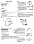
SS8-3 Shadow Sound System
User Manual
Thank you for purchasing our Dayton Audio Shadow Sound System. Please take a few minutes to read the
following information to insure proper installation and performance of the system.
Parts Inventory:
Your Shadow Sound system should include the following:
1. 8" Dual voice coil in-wall subwoofer with grill
3. Subwoofer cutout template and installation manual
2. Two 3" Satellite speakers with grill
4. Mounting hardware and grill removal tool
Installation Tools:
Having the following tools on hand will help the installation process go quicker and easier:
1. 2.
3.
5.
6.
7.
Pad of paper, pencil and a tape measure
Electric drill / screwdriver and bits
Utility knife and / or drywall saw
Hammer and wire staples
Wire strippers/crimp tool and diagonal cutters
Various types and sizes of hand screwdrivers
The following tools are optional but are recommended
for existing construction installations:
1. Stud / wire finder (Allows installer to find studs
and AC wire locations)
2. Multimeter (Allows installer to check for shorts,
opens and AC voltages)
Introduction:
The Dayton Audio Shadow Sound system was designed to meet the following criteria:
1. Extremely high quality audio (35-18,000 Hz ± 3 dB)
2. Creates a seamless rich sound environment
3. Aesthetically appealing...your wife will love them!
4. Unobtrusive 8" In-wall Subwoofer
5. Easy to install in new or existing homes
The “Shadow Sound” system provides beautiful rich sound while being nearly undetectable to the eye. The
system comes with an in-wall subwoofer that is easy to conceal along with two satellite speakers that are the
same size as a double gang electrical box. Don’t let the small size fool you! They utilize a specially designed
3" driver that features a powerful neodymium magnet and a ¾" Kapton voice coil for high power handling. The
in-wall sub contains an 8" dual voice coil woofer that delivers solid bass that you can feel. The “Big” sound
that is produced will amaze you! One Shadow Sound system is all you need for a small to medium size room
(up to 300 sq. ft.). For larger rooms, or in a room where TV sound is desired, two systems are recommended
to achieve a more evenly dispersed coverage. All the hardware is included except wire and double gang (or
round) electrical boxes to easily install in new construction or existing homes. Because the sub-woofer is installed low on the wall and the satellite speakers blend in with the electrical receptacles, the system is aesthetically pleasing and is able to create a seamless sound environment.
System Specifications: •Frequency response: 35-18,000 Hz •SPL: 88dB 1W/1m •Power handling: 50 watts
RMS/channel 100 watts max. •Impedance: 8 ohms per channel •Subwoofer dimensions: 10-1/8" Sq. x 3-13/16" D
•Satellite dimensions: (Square): 5" Sq. x 1-3/4" D (Round): 5-1/2" Dia. x 1-5/8" D •System weight: 18 lbs.
ROOM SURVEY/SYSTEM LAYOUT
The “Shadow” concept is based on mounting the satellite speakers at electrical receptacle height (See Fig1.).
By mounting the speakers at this level, pinpointing where the music is coming from becomes more difficult and
creates a seamless rich sound environment. When a Dayton Audio Shadow Sound System is installed correctly, the listener may walk from room to room and experience full and spacious sounding music. Speaker
location is critical to achieve this goal. Listed below are three basic system layouts. Because all installations
are different and have unique challenges, use these merely as a guide when laying out your whole house audio
system. When surveying rooms for possible satellite and bass unit locations, keep the following in mind:
1. Have a plan. Design and layout the complete
system on paper before cutting into the walls. It is
also a good idea to check local wiring codes before
you layout your system. Avoid running speaker
wire with electrical wire.
2. Be certain there are no electrical wires, water
pipes or heating ducts in the planned installation
area.
3. Locate satellites where they will not be behind
furniture. Keep in mind that directly under windows, in corners or next to doors make ideal locations for satellites.
4. Position the bass unit on a wall about a 1/3rd distance from the corner. Note: The closer you get
to the corner, the more bass output will be realized. Also, the bass unit should be mounted low
at a similar height as the satellite units. The bass
unit CAN be positioned behind furniture without
adverse effects.
"
(2)
FIG 1
STANDARD AREA
One “Shadow” system will perform very well in an area
of up to 300 square feet (approximately 15' x 20'). This
is the typical size of most kitchens, dining rooms,
living rooms and bedrooms. Figure 2. shows a basic
one system room layout. Avoid putting the satellites on the same wall or directly across from each
other on opposing walls. The two satellites should be
positioned so that they are the furthest distance in the
room in opposite corners. Note: The position of left
and right channels is not critical in a single system room layout.
LARGE AREA
Figure 3. illustrates a large open area or “Great” room
that will primarily be used for music. Two systems
perform very well in an area of up to 600 square feet
(approximately 20' x 30'). Note: Take notice in the
position of the left and right channels for each
system. This setup provides good stereo imaging
from any location in the room.
FIG 2
FIG 3
INSTALLING SPEAKERS
Once you have carefully selected the location of the system, you are ready to install speakers. Because all
installations are different and have unique challenges, you will need to be creative when installing your system.
Please keep in mind that having the proper tools on hand will make the job go faster and easier. Again, be
certain that there are no electrical wires, water pipes, or heating ducts in the planned installation area
before you start cutting into the walls.
SATELLITES
Again, to achieve optimum performance, it is very important to mount the satellite speakers at electrical outlet height or about 14" from the floor to the center of the speaker. The Shadow Sound satellite speakers use
standard double gang electrical boxes available from most hardware stores. Although they will work with most
brands, we recommend using Carlon brand boxes. Pre-construction (new work) and existing construction (old
work) boxes are available depending on your application.
Note: Shadow Sound satellite speakers should be mounted in a box and are NOT compatible with “mud
ring” style mounting hardware.
(3)
Ceiling Mounting a Shadow Sound System
Because all installations have unique challenges we have made available the Shadow Sound system
with round satellite speakers for applications that require ceiling mounting. By following the same
overall “system layout” principals but applying them to ceiling placement, satisfactory results can be
achieved. When laying out the satellite speakers in the ceiling make sure they are positioned ¼ distance from the room corner. The bass unit can be placed along a wall 1/3 distance from the room corner. As with the square satellites, we recommend using Carlon brand ceiling (new or old work) boxes.
Note: Shadow Sound satellite speakers should be mounted in a box and are NOT compatible
with “mud ring” style mounting hardware.
INSTALLING SPEAKERS
The Shadow Sound satellite speakers use standard double gang electrical boxes or round ceiling
boxes which are available at most hardware stores. Although they will work with most brands, we recommend using Carlon brand boxes. Pre-construction (new work) and existing construction (old work)
boxes are available depending on your application. Note: Shadow Sound satellite speakers should
be mounted in a box and are NOT compatible with “mud ring” style mounting hardware.
Pre-Construction “New Work”:
This is the best (and easiest) time to install the micro speakers. Follow these simple instructions:
1. Determine the desired location in the room. Using a hammer mount the box to a wall stud at electrical outlet height (see Fig.4) Make sure that the box protrudes out from the stud around 1/2" so it
will be flush with the drywall surface.
2. Run 18AWG, 2 conductor wire from speaker location to the location of the audio system. For
easier speaker connections, be sure to leave extra wire at both ends.
3. Only after the wall is finished and painted, should you attempt to install the micro speaker. To prevent damage, never install the micro speakers while the house is under construction.
4. Make electrical connections (see System Wiring). Using wire cutter / strippers, separate the two
conductors and remove about 1/2” of insulation from each wire. Twist the strands of wire tightly
before inserting them into the crimp connectors. When making connections, it is very important to observe proper polarity.
5. Install the satellite speaker using a hand held straight blade screwdriver. Be careful not to crack
the grill by over tightening the screws.
FIG 4
(4)
Existing Construction “Old Work”:
Before cutting a hole for the satellite speaker, make certain there are no obstructions in the wall. A
stud / wire finder is a very useful tool in determining this.
1. After you have found a suitable location, use the plastic “old work” box as a template and lightly
trace on the wall the cutout opening (approximately 3-3/4" x 3-3/4"). Make sure the marked cutout
area is square with the wall so when the speaker is installed it will be straight up and down.
2. If the wall is made of drywall, simply cut the marked area with a utility knife. If the wall is made of
plaster, you will need to drill holes at the four corners of the marked cutout area and use a drywall
or keyhole type saw to remove the lapboard and plaster.
3. Run 18AWG, 2 conductor wire from each speaker location to the location of the audio system.
For easier speaker connections, be sure to leave extra wire at both ends. Drill a wire hole up from
the basement or crawl space area into the interior wall cavity directly below the speaker location.
If this is not possible you will need to feed the wire down from the attic. Then simply feed the wire
up though the hole and out the cutout opening in the wall.
4. Install the double gang box into the wall cutout as per the manufactures’ instructions (see Fig.5).
Feed the wire through the opening at the back of the box.
5. Make electrical connections (see System Wiring). Using wire strippers, separate the two conductors and remove about 1/2" of insulation from each wire. Twist the strands of wire tightly before
inserting them into the crimp connectors. When making connections, it is very important to
observe proper polarity.
6. Install the satellite speaker using a hand held straight blade screwdriver. Be careful not to crack
the grill by over tightening the screws.
FIG 5
(5)
BASS UNIT
The bass unit was designed as an infinite baffle system and will operate properly only when installed in a wall.
In certain circumstances, you can mount the bass speaker in the ceiling with good results.
When mounting the bass unit in a wall, use the following procedure:
1. Determine the desired location in the room. Make certain this location is along a wall and is centered between two wall studs.
2. Using the supplied template and a pencil, mark the location for the opening.
3. Using a drywall saw, cut the opening in the wall.
4. Drill a wire hole up from the basement or crawl space area into the interior wall cavity directly below the
bass speaker location. If this is not possible you will need to feed the wire down from the attic. Because
the speakers are mounted low on the wall it is much easier to run the wire from the bottom up. Then simply
feed the wire up though the hole and out the cutout opening in the wall. The wire between each bass unit
and the home receiver or distribution panel should be at least an 18 AWG 4 conductor cable for a distance
of up to 50 feet. For longer runs, we recommend using 16 AWG. You should also run the satellite speaker
wires at this time so they can be connected to the bass unit.
5. Make electrical connections (see System Wiring). When making connections, it is very important to
observe proper polarity.
6. Mount the bass unit in the wall. Note: In new construction run wire to bass unit location and mark the wire
location so the bass unit can be installed after the drywall is in place.
SYSTEM WIRING
The system should be connected as shown in Figure 6. The satellites are connected to the bass speaker with
the bass unit. Looking at the bass unit you will find 4 sets of terminals. The satellites are connected to the satellite terminals. When making connections, it is very important to observe proper polarity. Make certain you
connect the positive “+” leads to the “red” terminals and the negative “-” leads to the “black” terminals.
When connecting a satellite speaker to the bass unit, the black lead with the white stipe is the “+” lead.
RUNNING WIRE
The wire between each bass unit and the home receiver or distribution panel should be at least an 18 AWG 4
conductor cable for a distance of up to 50 feet. For longer runs, we recommend using 16 AWG. Use 18 AWG 2
conductor cable between the satellites and bass unit. Note: If you are using volume controls, you should run 4
conductor cable from the distribution panel to the volume control and from the volume control to the bass unit.
Avoid running speaker wire with electrical wires! You should use code approved low voltage wire staples to
neatly attach your wires to floor joists and wall studs.
FIG 6
(6)
WHOLE HOUSE AUDIO SYSTEMS
If you plan on using several Shadow Speaker Systems on a single amplifier you will need to provide impedance
protection. There are a number ways to create a whole house audio system. Listed below are just a few of
them. Each method has its advantages and disadvantages. Choose the right system for your application.
VOLUME CONTROL FOR EACH ROOM
Figure 7 shows a typical four room whole house audio system. This type of system allows the user to independently control the volume level in each room. The volume controls provide the impedance protection while the
four room distribution panel allows quick and easy connection to any home receiver. This system can be expanded to up to ten rooms by using the SDP10 distribution panel and additional volume controls for each room.
FIG 7
ALL ROOMS SAME LEVEL
This type of system (See Fig.8) creates seamless sound distribution from room to room and is considered
the preferred method. If you have larger rooms and plan on using multiple speaker systems in one area, you
should use this type of system to ensure that the levels are the same. The IWS-4PDS Inwall Speaker Switch
provides the impedance protection and allows the user to listen to anyone or all (up to 4 pairs) speakers simultaneously. We recommend using a receiver that has a “RF” remote control or an “IR” repeater system so you
can control the system from any room in the house.
FIG 8
(7)
POWER REQUIREMENTS
The system will operate with an amp having a power range of 50-125 watts per channel. The benefits of an
expensive amp vs. a moderately priced unit are questionable. Approximately 90-95 dB average volume levels
per room can be achieved.
Warranty Information
Dayton Audio® products are constructed by industry experts, and are thoroughly tested before
shipment. Dayton Audio® products are warranted for the period of five years. This warranty is limited
to manufacturer defects, either in materials or workmanship. Dayton Audio® is not responsible for any
consequential on inconsequential damage to any other unit or component or the cost for installation or
extraction of any component of the audio system. In the rare case of a product failure, please contact
your place of purchase or call our Customer Support Department at (937) 743-8248.
Warranty Limitations
There are no other warranties, either express or implied, which extend the foregoing, and there are
no warranties of merchantability or fitness for any particular purpose. The warranty will not cover
incidental or consequential damage due to defective or improper use of products. This includes but
is not limited to burnt voice coils, overheating, bent frames, holes in the cone, or broken lead wires.
This warranty gives you specific legal rights and you may also have other rights which vary from
state to state.
Non-Warranty Service: If non-warranty service is required, the product may be sent to the
Company for repair/replacement, transportation prepaid, by calling (937) 743-8248 for details,
complete instructions, and service fee charges.
P.O. Box 52
Springboro, OH 45066-052
Phone: 1-937-743-8248
Email: [email protected]
daytonaudio.com
SS-09
© 2009 Dayton Audio®
(8)