1
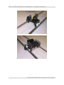
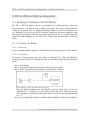
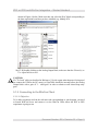
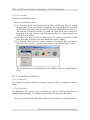
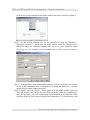
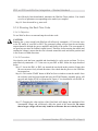
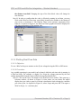
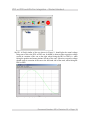
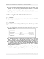
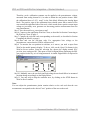
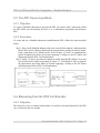
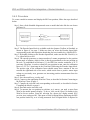
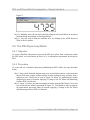
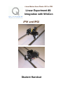
Linear Motion Servo Plants: IP01 or IP02
Linear Experiment #0:
Integration with WinCon
IP01 and IP02
Student Handout
IP01 or IP02 and WinCon Integration – Student Handout
Table of Contents
1. Objectives............................................................................................................................1
2. Prerequisites.........................................................................................................................1
3. References............................................................................................................................1
4. Experimental Setup..............................................................................................................2
4.1. Main Components........................................................................................................2
4.2. Wiring..........................................................................................................................2
5. IP01 or IP02 and WinCon Integration.................................................................................4
5.1. Applying a Voltage to the DC Motor...........................................................................4
5.1.1. Creating the Model...............................................................................................4
5.1.1.1. Objective.......................................................................................................4
5.1.1.2. Procedure......................................................................................................4
5.1.2. Connecting to the WinCon Client........................................................................5
5.1.2.1. Objective.......................................................................................................5
5.1.2.2. Procedure......................................................................................................6
5.1.3. Compiling the Model...........................................................................................6
5.1.3.1. Objective.......................................................................................................6
5.1.3.2. Procedure......................................................................................................6
5.1.4. Running the Real-Time Code...............................................................................8
5.1.4.1. Objective.......................................................................................................8
5.1.4.2. Procedure......................................................................................................8
5.1.5. Plotting Real-Time Data.......................................................................................9
5.1.5.1. Objective.......................................................................................................9
5.1.5.2. Procedure......................................................................................................9
5.2. Measuring from the IP01 Cart Potentiometer............................................................11
5.2.1. Objective............................................................................................................11
5.2.2. Procedure............................................................................................................11
5.3. The IP01 Open-Loop Block.......................................................................................13
5.3.1. Objective............................................................................................................13
5.3.2. Procedure............................................................................................................13
5.4. Measuring from the IP02 Cart Encoder.....................................................................13
5.4.1. Objective............................................................................................................13
5.4.2. Procedure............................................................................................................14
5.5. The IP02 Open-Loop Block.......................................................................................15
5.5.1. Objective............................................................................................................15
5.5.2. Procedure............................................................................................................15
6. Knowledge Test.................................................................................................................16
Document Number: 502 ! Revision: 03 ! Page: i
IP01 or IP02 and WinCon Integration – Student Handout
1. Objectives
In this introductory session you will become familiar with WinCon and the IP01 or IP02
servo experiment. At the end of the session you will know the following:
The main components comprising this basic setup (e.g. data acquisition board, power
amplifier, real-time control software).
How to wire up the system.
How to create a Simulink based controller and run it in realtime using WinCon (i.e.
Quanser's Windows-based real-time control software).
How to measure and display, using a Simulink diagram, the encoder and/or
potentiometer signals.
How to apply and display, using a Simulink diagram, a varying voltage to the IP01 or
IP02 DC motor.
How to construct a Simulink block (i.e. subsystem) that represents the IP01 or IP02
servo system.
2. Prerequisites
To successfully carry out this introductory laboratory, the prerequisites are:
i) To be familiar with your IP01 or IP02 main components, (e.g. actuator, sensors), your
power amplifier (e.g. UPM), and your data acquisition card (e.g. MultiQ), as
described in References [1], [2], and [3].
ii) To be familiar with the complete wiring of your IP01 or IP02 servo plant, as per
dictated in Reference [1].
3. References
[1]
[2]
[3]
[4]
IP01 and IP02 User Manual.
MultiQ User Manual.
Universal Power Module User Manual.
WinCon User Manual.
Document Number: 502 ! Revision: 03 ! Page: 1
IP01 or IP02 and WinCon Integration – Student Handout
4. Experimental Setup
4.1. Main Components
To setup this preparatory laboratory, the following hardware and software are required:
Power Module:
Data Acquistion Board:
Quanser UPM 1503 / 2405, or equivalent.
Quanser MultiQ PCI / MQ3, or equivalent.
Linear Motion Servo Plant: Quanser IP01 or IP02, as shown in Figures 1 and 2, respectively.
Real-Time Control Software:
The WinCon-Simulink-RTX configuration, as
detailed in the Reference [4], or equivalent.
For a complete and detailed description of the main components comprising this setup,
please refer to the manuals corresponding to your configuration.
4.2. Wiring
To wire up the system, please follow the default wiring procedure for your IP01 or IP02 as
fully described in Reference [1]. When you are confident with your connections, you can
power up the UPM.
Document Number: 502 ! Revision: 03 ! Page: 2
IP01 or IP02 and WinCon Integration – Student Handout
Figure 1 IP01 System
Figure 2 IP02 System
Document Number: 502 ! Revision: 03 ! Page: 3
IP01 or IP02 and WinCon Integration – Student Handout
5. IP01 or IP02 and WinCon Integration
5.1. Applying a Voltage to the DC Motor
The IP01 or IP02 DC motor is driven by an amplifier (e.g. UPM) suitable to deliver the
desired power to it. In order to drive a voltage to the motor, you need to output the desired
voltage to the desired D/A (i.e. Digital-to-Analog) channel of your data acquisition card
(e.g. MultiQ-PCI), that is to say the D/A channel connected to the power amplifier. From
the wiring you performed, following the instructions described in [1], it is known that D/A
channel #0 on the MultiQ drives the UPM 1503, which in turn drives the IP01 or IP02 DC
motor.
5.1.1. Creating the Model
5.1.1.1. Objective
Create a Simulink model to generate a desired voltage from analog ouput # 0 of the MultiQ.
5.1.1.2. Procedure
To output a slowing-varying sine wave voltage of amplitude 1.5 V from the Digital-toAnalog Converter (DAC) of the board that you have installed, follow the steps described
below:
Step 1. Start Matlab.
Step 2. Launch the Simulink Library Browser and open a new model.
Step 3. Build a Simulink diagram similar to the one shown in Figure 3.
Figure 3 Diagram to Apply a Sine Wave Voltage to the D/A
Keep the default parameters for the Simulink sine wave block, that is to say, an
amplitude of 1, a frequency of 1 rad/s, and zero bias and phase. Therefore, the sine
wave amplitude, as fed to the analog output block, is set by the subsequent gain block
to 1.5 V.
Step 4. The Analog Output block is available under the Quanser Toolbox in Simulink, as
Document Number: 502 ! Revision: 03 ! Page: 4
IP01 or IP02 and WinCon Integration – Student Handout
shown in Figure 4, below. Make sure that you select the DAC block corresponding to
the data acquisition board that you have installed (e.g. MultiQ-PCI).
Figure 4 Quanser Toolbox and Data Acquisition Blocks
Step 5. By double-clicking on the Analog Output block, make sure that the Channel(s) to
Use: input field is set to 0.
CAUTION:
If a "To Load" cable (as described in Reference [1]) with a gain other than one is being used
(to connect the UPM to the DC motor), a Gain block should be inserted before the Analog
Output block with a gain of "1 / cable gain" in order to obtain overall closed-loop unity
gain.
5.1.2. Connecting to the WinCon Client
5.1.2.1. Objective
To be able to generate and run the real-time code corresponding to your diagram, you need
to launch WinCon Server and connect it to the WinCon Client where the IP01 or IP02
experiment is going to run.
Document Number: 502 ! Revision: 03 ! Page: 5
IP01 or IP02 and WinCon Integration – Student Handout
5.1.2.2. Procedure
Follow the steps described below:
Step 6. Launch WinCon Server.
Step 7. Determine the PC that is going to run the IP01 or IP02 setup. This PC, running
the experiment, is the one connected, through the data acquisition board, to the IP01
or IP02 plant. This can be either the same PC as the one running WinCon Server (i.e.
where the user is located) or another (i.e. remote) PC in the lab. In case a remote PC is
being used to run the real-time code (and therefore WinCon Client), determine and
write down its IP address.
Step 8. Ensure that WinCon Client is running on the PC connected to the IP01 or IP02
plant. By default, WinCon Client starts minimized in the PC taskbar.
Step 9. From the WinCon Server window, connect to the desired WinCon Client by
using the Client | Connect... option from the menu bar, as shown in Figure 5, below.
Figure 5 Connecting WinCon Server to WinCon Client
You can then enter in the input dialog box the IP address of the PC running WinCon
Client.
5.1.3. Compiling the Model
5.1.3.1. Objective
To compile the designed model into real-time code that will be executable by WinCon
Client.
5.1.3.2. Procedure
The building of the real-time code is achieved by using the WinCon menu from the
Simulink diagram window. To compile the model, follow the steps described below:
Step 10. Set the Real-Time Workshop parameters for WinCon by executing WinCon |
Document Number: 502 ! Revision: 03 ! Page: 6
IP01 or IP02 and WinCon Integration – Student Handout
Set WinCon Options option from the model window menu bar, as shown in Figure 6.
Figure 6 Executing Set WinCon Options
Step 11. Set the desired sampling rate for the controller by using the Simulation |
Simulation parameters... option from the model window menu bar. This opens up a
dialog box where the controller sampling time can be set in the input box named
Fixed step size. For example, set the sampling time to 0.001 second, as shown in
Figure 7.
Figure 7 Setting the Sampling Time
Step 12. Although this is done automatically when the code is being built, you can also
set the model simulation mode to External, by checking the Simulation | External
option from the model window menu bar.
Step 13. Finally, select the WinCon | Build option from the model window menu bar.
This will generate and compile the code from the model. When the compilation is
done, the real-time code will automatically be downloaded to the WinCon Client,
which the WinCon Server has previously been connected to. To check that the code
Document Number: 502 ! Revision: 03 ! Page: 7
IP01 or IP02 and WinCon Integration – Student Handout
has effectively been downloaded, maximize the WinCon Client window. You should
see a list of parameters corresponding to the model you compiled.
Step 14. Save the model as q_motor.mdl.
5.1.4. Running the Real-Time Code
5.1.4.1. Objective
To use WinCon Server to start and stop the real-time code.
CAUTION:
Running the q_motor model with WinCon will effectively command a 1.5-Volt sine wave
to the DC motor of your IP01 or IP02. The generated voltage will go from the card analog
output channel 0 through the power amplifier and finally to the motor. This corresponds to
an open-loop test since no feedback signal is used. Therefore, before starting the model (and
sending the voltage), ensure that the cart is located around the track mid-stroke position and
is free to move in both directions.
5.1.4.2. Procedure
Now that the code has been compiled and downloaded, it can be run in real-time. To do so
and effectively command a 1.5 V sine wave to your IP01 or IP02, follow the steps described
below:
Step 15. Locate the IP01 or IP02 cart around the track mid-stroke position. Ensure that
the cart can move freely in both directions. Also check that the power to the UPM has
been turned on.
Step 16. Click on the START button in WinCon Server window to start the model. Once
the real-time code has been started and runs, the START button, originally green, will
turn red and display STOP, as illustrated in Figure 8. You should now see the IP01 or
IP02 cart move slowy back and forth along the track.
Figure 8 WinCon Server
Step 17. Changing the value on-line of the Gain block will change the amplitude of the
commanded voltage and will directly affect the speed of the motor/cart. Be aware
that a larger voltage will not only result in an increase the cart velocity but also
Document Number: 502 ! Revision: 03 ! Page: 8
IP01 or IP02 and WinCon Integration – Student Handout
the distance travelled! Changing the sign of the Gain block value will change the
cart direction.
Step 18. In order to confirm that the code is effectively running in real-time, you may
click on the WinCon Client icon, most likely located in the taskbar at the bottom of
your screen, to maximize it. The WinCon Client is the real-time component of the
software. As shown in Figure 9, the WinCon Client's graphical interface displays the
real-time performances of the running code.
Figure 9 WinCon Client
5.1.5. Plotting Real-Time Data
5.1.5.1. Objective
To use a WinCon Scope to monitor on-the-fly the voltage driving the IP01 or IP02 motor.
5.1.5.2. Procedure
Any variable appearing in your model can be plotted, while the real-time code is running, in
a WinCon Scope. For example, to display in a Scope the voltage generated by the card
analog output and driving the motor, follow the steps described below:
Step 19. Click on the Open Plot button in the WinCon Server toolbar. This opens up a
selection window, as shown in Figure 10, from where you can choose the model
display that you wish to open for real-time visualization. and selecting the variables
you want to plot. As depicted in Figure 10, select Scope and press OK. This opens a
WinCon Scope, i.e. a real-time plot.
Document Number: 502 ! Revision: 03 ! Page: 9
IP01 or IP02 and WinCon Integration – Student Handout
Figure 10 Opening a WinCon Scope
Step 20. A Scope similar to the one shown in Figure 11 should plot the actual voltage
being sent to drive the IP01 or IP02 cart. It should be observed that a positive voltage
results in a motion of the cart to the right, when facing the IP01 or IP02 (i.e. when
facing the position and motor pinions in front of the cart). Likewise a negative voltage
should result in a motion of the cart to the left-hand side of the track, when facing the
IP01 or IP02.
Figure 11 Output Voltage Displayed in a WinCon Scope
Document Number: 502 ! Revision: 03 ! Page: 10
IP01 or IP02 and WinCon Integration – Student Handout
Step 21. You can also save the data acquired in the real-time plot into a Matlab file by
using the File | Save item from the WinCon Scope menu bar. Refer to the WinCon
User's Manual (i.e. Reference [4]) for complete details on saving data.
Step 22. You may wish to stop the controller now, by clicking on the STOP button in
WinCon Server toolbar.
5.2. Measuring from the IP01 Cart Potentiometer
5.2.1. Objective
The objective is now to monitor and measure, in real-time, the actual position of the IP01
cart, as sensed by the cart potentiometer.
5.2.2. Procedure
To create a model to measure and display the IP01 cart position, follow the steps described
below:
Step 1. Start a fresh Simulink diagram and create a model that looks like the one shown
in Figure 12, below.
Figure 12 Measuring from the IP01 Cart Potentiometer
Step 2. The Analog Input block is available under the Quanser Toolbox in Simulink, as
shown in Figure 4, on page 5. Make sure that you select the Analog Input block
corresponding to the data acquisition board that you have installed (e.g. MultiQ-PCI).
Step 3. By double-clicking on the Analog Input block, make sure that the Channel(s) to
Use: input field is set to 0. The range(s): input field can keep the default value of 5,
since the cart potentiometer output signal has a range of ±5 VDC over its 10 complete
turns, as explained in Reference [1].
Step 4. The potentiometer generates an analog signal proportional to the position pinion
angle of rotation, which is in turn directly proportional to the cart position on the rack.
As established in Reference [1], the IP01 cart potentiometer sensitivity is 93.1 mm/V.
Document Number: 502 ! Revision: 03 ! Page: 11
IP01 or IP02 and WinCon Integration – Student Handout
Therefore, such a calibration constant can be applied to the potentiometer voltage,
measured from analog channel # 0, in order to obtain the cart position in mm. Enter
the calibration factor of +93.1 mm/V in the Gain block following the Analog Input
block. The positive sign of the calibration factor should ensure that a motion of the
cart towards the right-hand side of the track, which results from a positive motor input
voltage as previously seen, generates an increasing position measurement from the
cart potentiometer.
Step 5. Save the model as q_potentiometer.mdl.
Step 6. Connect to the appropriate WinCon Client, as described in Section Connecting to
the WinCon Client, on page 5.
Step 7. Compile the real-time code corresponding to the model, as described in Section
Compiling the Model, on page 6.
Step 8. Start and run the real-time code. For appropriate bias voltage to the
potentiometer, ensure that the UPM is still turned on.
Step 9. To measure the cart position in real-time, as it moves, you need to open from
WinCon the model numeric display. To do so, click on the Open Plot button in the
WinCon Server toolbar. From the selection list, choose the display named IP01
position (mm), and press OK. This opens a WinCon Digital Meter displaying the IP01
cart position on-the-fly, as it is being measured. A similar Digital Meter is depicted in
Figure 13.
Figure 13 Digital Meter: IP01 Cart Position (mm)
Step 10. Manually move the cart back and forth along the track and follow its measured
position change accordingly on the Digital Meter.
Step 11. You may wish to stop the controller now, by clicking on the STOP button in
WinCon Server toolbar.
Note:
You can adjust the potentiometer pinion rotation relative to the rack such that the zero
measurement corresponds to the desired "zero" position of the cart on the track.
Document Number: 502 ! Revision: 03 ! Page: 12
IP01 or IP02 and WinCon Integration – Student Handout
5.3. The IP01 Open-Loop Block
5.3.1. Objective
To create a Simulink subsystem to represent the IP01 servo plant. Such a subsystem, called
the IP01 block, can conveniently be used, as is, in subsequent experiments involving the
IP01.
5.3.2. Procedure
To create and use a Simulink subsystem symbolizing the IP01, follow the steps described
below:
Step 1. Start a fresh Simulink diagram and create a model that contains a subsystem that
has the IP01 motor voltage as input and the potentiometer reading (in mm) as output.
Such a subsystem (a.k.a. block) can be seen in Figure 14, below, as combining the
models designed previously in Sections Applying a Voltage to the DC Motor and
Measuring from the IP01 Cart Potentiometer.
Step 2. Figure 15, below, provides an example of model using the IP01 block. Create and
run in real-time the model represented in Figure 15. You should be able to replicate
the observations previously made in Sections Applying a Voltage to the DC Motor
and Measuring from the IP01 Cart Potentiometer.
Figure 15 Model using the IP01 Subsystem
Figure 14 IP01 Subsystem
5.4. Measuring from the IP02 Cart Encoder
5.4.1. Objective
The objective is now to monitor and measure, in real-time, the actual position of the IP02
cart, as sensed by the cart encoder.
Document Number: 502 ! Revision: 03 ! Page: 13
IP01 or IP02 and WinCon Integration – Student Handout
5.4.2. Procedure
To create a model to measure and display the IP02 cart position, follow the steps described
below:
Step 1. Start a fresh Simulink diagram and create a model that looks like the one shown
in Figure 16.
Figure 16 Measuring from the IP02 Cart Encoder
Step 2. The Encoder Input block is available under the Quanser Toolbox in Simulink, as
shown in Figure 4, on page 5. Make sure that you select the Encoder Input block
corresponding to the data acquisition board that you have installed (e.g. MultiQ-PCI).
Step 3. By double-clicking on the Encoder Input block, make sure that the Channel(s) to
Use: input field is set to 0.
Step 4. The encoder generates an integer number of counts proportional to the position
pinion angle of rotation, which in turn is directly proportional to the cart position on
the rack. As established in Reference [1], the IP02 cart encoder resolution is 22.75
µm/count. Therefore, in order to obtain the cart position in mm, enter the calibration
factor of +22.75e-3 mm/count in the Gain block following the Encoder Input block.
The positive sign of the calibration factor should ensure that a motion of the cart
towards the right-hand side of the track, which results from a positive motor input
voltage as previously seen, generates an increasing position measurement from the
cart encoder.
Step 5. Save the model as q_encoder.mdl.
Step 6. Connect to the appropriate WinCon Client, as described in Section Connecting to
the WinCon Client, on page 5.
Step 7. Compile the real-time code corresponding to the model, as described in Section
Compiling the Model, on page 6.
Step 8. Start and run the real-time code.
Step 9. To measure the cart position in real-time, as it moves, you need to open from
WinCon the model numeric display. To do so, click on the Open Plot button in the
WinCon Server toolbar. From the selection list, choose the display named IP02
position (mm), and press OK. This opens a WinCon Digital Meter displaying the IP02
cart position on-the-fly, as it is being measured. Such a Digital Meter is depicted in
Document Number: 502 ! Revision: 03 ! Page: 14
IP01 or IP02 and WinCon Integration – Student Handout
Figure 17.
Figure 17 Digital Meter: IP02 Cart Position (mm)
Step 10. Manually move the cart back and forth along the track and follow its measured
position change accordingly on the Digital Meter.
Step 11. You may wish to stop the controller now, by clicking on the STOP button in
WinCon Server toolbar.
5.5. The IP02 Open-Loop Block
5.5.1. Objective
To create a Simulink subsystem to represent the IP02 servo plant. Such a subsystem, called
the IP02 block, can conveniently be used, as is, in subsequent experiments involving the
IP02.
5.5.2. Procedure
To create and use a Simulink subsystem symbolizing the IP02, follow the steps described
below:
Step 1. Start a fresh Simulink diagram and create a model that contains a subsystem that
has the IP02 motor voltage as input and the encoder reading (in mm) as output. Such a
subsystem (a.k.a. block) can be seen in Figure 18, below, as combining the models
designed previously in Sections Applying a Voltage to the DC Motor and Measuring
from the IP02 Cart Encoder.
Step 3. Figure 19, below, provides an example of model using the IP02 block. Create and
run in real-time the model represented in Figure 19. You should be able to replicate
the observations previously made in Sections Applying a Voltage to the DC Motor
and Measuring from the IP02 Cart Encoder.
Document Number: 502 ! Revision: 03 ! Page: 15
IP01 or IP02 and WinCon Integration – Student Handout
Figure 19 Model using the IP02 Subsystem
Figure 18 IP02 Subsystem
6. Knowledge Test
As this is an introductory session, there is no report to write. You should however ensure
that you have understood the principles of operation of your hadware (e.g. IP01 or IP02,
MultiQ, UPM) and WinCon. You should also have a good understanding of how positions
are measured and how the voltage is applied to the motor. In order to ensure that you
understand the complete system, please assure that you can reply to the following questions
correctly (and confidently!):
1)
How many actuators and how many sensors does the IP01 system have?
2)
How many actuators and how many sensors does the IP02 system have?
3)
Which D/A channel drives the UPM? the DC motor?
4)
Which analog input channel measures the IP01 cart potentiometer voltage?
5)
Which encoder channel measures the IP02 cart encoder counts?
6)
Why is the sign of the calibration constant important?
7)
Why does the cable gain have to be compensated for in the motor model?
Document Number: 502 ! Revision: 03 ! Page: 16