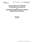
1
High-Performance, Standalone In-System Programmer FRPXIA3 User’s Manual FlashRunner FRPXIA3 High-Performance Gang In-System Programmer PXI Module User’s Manual Revision 1.0 — June 2014 Copyright © 2014 SMH Technologies DC10665 We want your feedback! SMH Technologies is always on the lookout for new ways to improve its Products and Services. For this reason feedback, comments, suggestions or criticisms, however small, are always welcome. Our policy at SMH Technologies is to comply with all applicable worldwide safety and EMC/EMI regulations. Our products are certified to comply with the European New Approach Directives and the CE mark is applied on all our products. This product as shipped from the factory has been verified to meet with requirements FCC as a CLASS A product. In a domestic environment, this product may cause radio interference in which case the user may be required to take adequate prevention measures. Attaching additional wiring to this product or modifying the product operation from the factory default as shipped may effect its performance and cause interference with other apparatus in the immediate vicinity. If such interference is detected, suitable mitigating measures should be taken. SMH Technologies E-mail (general information): [email protected] E-mail (technical support): [email protected] Web: http://www.smh-tech.com Important SMH Technologies reserves the right to make improvements to FlashRunner, its documentation and software routines, without notice. Information in this manual is intended to be accurate and reliable. However, SMH Technologies assumes no responsibility for its use; nor for any infringements of rights of third parties which may result from its use. SMH TECHNOLOGIES WILL NOT BE LIABLE FOR DAMAGES RESULTING FROM LOSS OF DATA, PROFITS, USE OF PRODUCTS, OR INCIDENTAL OR CONSEQUENTIAL DAMAGES, EVEN IF ADVISED OF THE POSSIBILITY THEREOF. Trademarks SMH Technologies is the licensee of the SofTec Microsystems trademark. All other product or service names are the property of their respective owners. FlashRunner FRPXIA3 User’s Manual Contents 0 Before Starting 9 0.1 0.2 0.3 0.4 1 Overview 11 1.1 1.2 1.3 1.4 1.5 2 Important Notice to Users 9 Safety 9 Getting Technical Support 10 Additional Documentation 10 What is FlashRunner FRPXIA3? 11 1.1.1 General features 12 1.1.2 Hardware features 12 1.1.3 Software features 13 Package Checklist 13 Hardware Overview 14 1.3.1 Front Panel LEDs 16 1.3.2 ISP Connector 17 Programming Algorithms and Licenses 17 1.4.1 Installing New Licenses 17 Upgrading the Firmware 18 System Setup 19 2.1 2.2 2.3 2.4 2.5 Overview 19 Installing the module 19 2.2.1 Interfacing FlashRunner FRPXIA3 with your Test/Programming Equipment 20 Software Setup 20 2.3.1 Windows 8 and 8.1 Software Setup 21 Step-by-Step Tutorial: Sending Commands to FlashRunner 24 Step-by-step tutorial: user application example 30 Contents 3 Connectors 33 3.1 3.2 4 Overview 33 ISP Connectors 33 Technical Specifications 35 4.1 4.2 4.3 4.4 Absolute Maximum Ratings 35 DC Characteristics and Functional Operating Range 35 AC Characteristics 37 Physical and Environmental Specifications 38 FlashRunner FRPXIA3 User’s Manual Index of Figures Figure 1: FlashRunner FRPXIA3 11 Figure 2: FlashRunner FRPXIA3 lateral view 14 Figure 3: FlashRunner FRPXIA3 schematic blocs 15 Figure 4: FlashRunner FRPXIA3, front panel view 16 Figure 5:Windows 8 charms bar 22 Figure 6: Windows 8, PC Settings 22 Figure 7: Windows 8: Advanced Startup 23 Figure 8: Windows 8: Startup Settings 23 Figure 9: Software Setup, restart window 24 Figure 10: FlashRunner FRPXIA3 Control Panel 25 Figure 11: FlashRunner Control Panel, Target Device Configured 27 Figure 12: FlashRunner FRPXIA3 Control Panel, Binary File Conversion 28 Figure 13: FRPXIA3 Control Panel, User Application Example 30 Figure 14: User Application Example, “RUN PARALLEL” 32 Figure 15: Load Conditions 38 FlashRunner FRPXIA3 User’s Manual Index of Tables Table 1: Programming Status LED description 17 Table 2: ISP Connector Signals 33 Table 3: Absolute Maximum Ratings 35 Table 4: DC Characteristics and Functional Operating Range 36 Table 5: AC Characteristics 37 Table 6: Physical and Environmental Specifications 38 FlashRunner FRPXIA3 User’s Manual 0 0 Before Starting i Note: the FlashRunner System Software CD-ROM and/or SMH Technologies website (www.smh-tech.com) may contain an updated version of this user’s manual. Please check before continuing reading this documentation. 0.1 Important Notice to Users While every effort has been made to ensure the accuracy of all information in this document, SMH Technologies assumes no liability to any party for any loss or damage caused by errors or omissions or by statements of any kind in this document, its updates, supplements, or special editions, whether such errors are omissions or statements resulting from negligence, accidents, or any other cause. 0.2 Safety FlashRunner is a low-voltage device. However, when integrating it inside an automatic test equipment or when interfacing it with other systems, take all precautions in order to avoid electrical shocks due to, for example, different ground references. Make all connections to the target system before applying power to the instrument. To protect FlashRunner against electrostatic discharge (ESD), always connect yourself to ground (e.g. via wrist straps) when handling the instrument. Always store FlashRunner inside an antistatic bag when not in use. 9 Before Starting 0 0.3 Getting Technical Support SMH Technologies is continuously working to improve FlashRunner firmware and to release programming algorithms for new devices. SMH Technologies offers a fast and knowledgeable technical support to all of its customers and is always available to solve specific problems or meet specific needs. To get in touch with SMH Technologies, please refer to the contact information below. Phone: +39 0434 421111 Fax: +39 0434 639021 Technical Support: [email protected] 0.4 Additional Documentation This user’s manual provides information about how to setup FlashRunner FRPXIA3 and its hardware characteristics. For information about FlashRunner commands and their syntax, including specific commands for specific family of microcontrollers, please refer to the FlashRunner Programmer’s Manual, included (in PDF format) in the FlashRunner CD-ROM. 10 FlashRunner FRPXIA3 User’s Manual 0 1 Overview 1.1 What is FlashRunner FRPXIA3? FlashRunner FRPXIA3 is a universal high-integrated in-system gang programmer for PXI and CompactPCI systems. FlashRunner FRPXIA3 is designed for programming multi-PCB panel assemblies, and it is based on FlashRunner technology, the fast and reliable programming system for Flash-based microcontroller and serial memories Figure 1: FlashRunner FRPXIA3 FRPXIA3 has 3 fully parallel and independent ISP (In-System-Programming) channels. Each ISP channel is composed of: • Five digital, bi-directional lines; • Two analog/digital lines (analog out, digital in/out); 11 Overview 1 • One programmable clock output • Two power lines; • One ground line (common for all channels). 1.1.1 • Fast programming algorithms developed to reach the memory technology speed limit of the target device; • PXI and CompactPCI chassis compatibility; • Supports most ISP protocols (BDM, JTAG, SPI, I2C, MON, ICC, SCI, etc.); • Flexible, fully configurable; • Compact and robust design for production environments; • Data integrity guaranteed (every data transfer to/from the host system or Secure Digital card is CRC tagged); • Safe and reliable (projects and code images are stored on memory cards inside the board). 1.1.2 12 General features Hardware features • CompactPCI 2.0 R3.0 compliant, PXI fully compatible • Integrated in only one slot of your PXI or CompactPCI chassis • Support 3.3V and 5V PCI signal • 33MHz PCI bus • 3 true parallel in system programming channels. For each channel: • Five digital I/O lines • Two digital I/O or analog output lines • Two programmable voltages • One programmable clock output • 512 bytes on-board dynamic memory for each channel; • Standard off-the-shelf D-SUB 50 pin ISP connector • Programming status LED output for each channel (BUSY, PASS, FAIL) FlashRunner FRPXIA3 User’s Manual 1.1.3 0 Software features • Interface Library DLL to control the instrument from user written applications; • LabVIEW examples source code; • Control Panel Utility for fast and easy system setup; • ASCII-Based commands; • Optional Data Protection System to make the contents of the binary file to be programmed to the target device not readable (and not duplicable) by non-authorized people; • Log Files; • Erase, blank check, program, read, verify, oscillator trimming, etc; • FlashRunner's open architecture makes its firmware easily upgradeable to support both new devices and new features. 1.2 Package Checklist The FlashRunner FRPXIA3 package includes the following items: • FlashRunner FRPXIA3 unit, including SD cards already pre-installed with the programming algorithm(s) you specified at the time of purchase; One meter ISP cable 50 pins 1-side unterminated; • • FlashRunner FRPXIA3 System Software CD-ROM; This User Manual; • A registration card; • 13 Overview 1 1.3 Hardware Overview FRPXIA3 is composed of a PXI/CompactPCI interface and 3 independent programming channels. The Master Controller (MC) bridges the commands from the PCI bus to the three Programming Engines. Figure 2: FlashRunner FRPXIA3 lateral view The figure below shows you the schematic blocs of the FRPXIA3 module: 14 FlashRunner FRPXIA3 User’s Manual 0 Figure 3: FlashRunner FRPXIA3 schematic blocs • MC: Master Controller; • ENG1: Programming Engine 1; • ENG2: Programming Engine 2; • ENG3: Programming Engine 3; 15 Overview 1 1.3.1 Front Panel LEDs Figure 4: FlashRunner FRPXIA3, front panel view There are two LEDs for each programming channel: 16 • One LED for the Master Controller; o Blinking during system initialization o ON after initialization • “Engine status LED” on the right (refer to the FlashRunner Programmer’s Manual chapter 11.2); • “Programming status LED” on the left (multicolor LED: BLUE, RED, GREEN): FlashRunner FRPXIA3 User’s Manual 0 Table 1: Programming Status LED description Color Description OFF No programming has been performed yet BLUE FlashRunner is busy programming RED The previous programming has ended with errors GREEN The previous programming has been successful 1.3.2 ISP Connector The D-SUB 50 pins male is the in-system programming connector. The pinout is available at the end of this manual. 1.4 Programming Algorithms and Licenses FlashRunner FRPXIA3 includes programming algorithms for several devices. In order to program a specific device, however, a specific license file for that device must be purchased. i Note: FlashRunner FRPXIA3 comes already preinstalled with the license(s) you specified at the moment of purchase. You can purchase additional licenses at any future moment. Programming algorithms and license files are stored in the SD card (see the FlashRunner Programmer’s Manual for more information). 1.4.1 Installing New Licenses When you buy an additional license for a specific device, you will get: § § § An algorithm file (.alg); A license file (.lic); A device-specific script example (.frs). 17 Overview 1 The .alg file contains the actual programming algorithm for the requested device (and several other devices of the same family). The .lic file contains an unlocking code that will let you use the programming algorithm. A license file enables the use of a specific programming algorithm on a specific FlashRunner instrument (licenses are serial number specific). The script file contains an example of script to use as a starting point for your specific programming needs (for more information on scripts, see the FlashRunner Programmer’s Manual). To install the new license, do the following (for each programming module): 1. Copy the .alg file into the \ALGOS directory of the SD card (if an .alg file with the same name already exists, overwrite it); 2. Copy the .lic file into the \LICENSES directory of the SD card. To copy files on the SD card, use either a standard card reader connected to a PC or transfer the files using the FlashRunner FSSENDFILE command (for more information on FlashRunner commands, see the FlashRunner Programmer’s Manual). Alternatively, you can use the FlashRunner FRPXIA3 Control Panel utility to install new programming algorithms and licenses. For more information on the FlashRunner FRPXIA3 Control Panel please refer to the FlashRunner Programmer’s Manual. 1.5 Upgrading the Firmware The FlashRunner engine firmware can be easily upgraded using the provided Control Panel utility. For more information, please refer to the FlashRunner Programmer’s Manual. 18 FlashRunner FRPXIA3 User’s Manual 0 2 System Setup 2.1 Overview i Note: the example shows how to set up the system for programming a Freescale MC68HC908QY4 microcontroller. For how to connect to other target devices, please refer to the FlashRunner Programmer’s Manual. This chapter will explain how to set up FlashRunner FRPXIA3 for the first time. The examples in this chapter will use the host system to send commands to FlashRunner. When moving FlashRunner to the production environment, you can take full advantage of the instrument’s SD cards to make the instrument work without being controlled by the host system using script files. For more information about the use of script files, see the FlashRunner Programmer’s Manual. 2.2 Installing the module Please follow these steps for the FlashRunner FRPXIA3 installation: 1. Power off and unplug the PXI/CompactPCI chassis; 2. Align the module’s edge with the card guide in the PXI/CompactPCI chassis; 3. Slide the module into the chassis until the ejector handle locks in the up position; 4. Tighten the screw on the front panel; 5. Power on the PXI/CompactPCI chassis; 6. If you are using a Remote Controller you must restart the PC; 19 System Setup FlashRunner FRPXIA3 removing: 1. 2. 3. 4. 3 2.2.1 Power off and unplug the PXI/CompactPCI chassis; Untighten the screw on the front panel; Push the ejector handle in the down position; Slide out the module from the PXI/CompactPCI chassis; Interfacing FlashRunner FRPXIA3 with your Test/Programming Equipment One-meter ISP cable is provided in the delivery package. The cable is 1-side unterminated that allow you to interface with your test/programming equipment. Make all the required connections (power, oscillator, ISP signals) to the target microcontroller. Typical connections for all the device families supported by FlashRunner are shown in the FlashRunner Programmer’s Manual. 2.3 Software Setup The FlashRunner FRPXIA3 system software setup installs all of the required components to your hard drive. These components include: • • • • • • • 20 The FRPXIA3 Windows driver; The FlashRunner FRPXIA3 Control Panel Utility; Script examples; Interface Library (DLL) ; Source code example in Visual C++ 2008; FlashRunner FRPXIA3 Control Panel Utility source code in LabVIEW: o Source code for LabVIEW 2013 o Source code for LabVIEW 2010 o Source code for LabVIEW 8.6 Documentations in PDF format; FlashRunner FRPXIA3 User’s Manual i Note: to install the FlashRunner FRPXIA3 system software you must log in as Administrator. i Note: to install the FlashRunner FRPXIA3 system software on Windows 8 and 8.1 machine see chapter 2.3.1. 0 Insert the “System Software” CD-ROM into your computer’s CD-ROM Drive. Open the CD-ROM drive folder and double click on the setup file: • • Setup32.exe for 32bit Windows Operating System; Setup64.exe for 64bit Windows Operating System; Then follow the on-screen instructions. FlashRunner FRPXIA3 system software is compatible with Windows XP, 7, 8 and 8.1, x32 and x64 system platform. Windows 8 and 8.1 needs a particular installing procedure, see the chapter here below. 2.3.1 Windows 8 and 8.1 Software Setup Follow these steps: 1. You have to disable the driver signature enforcement a. Hover your mouse to the right hand bottom corner to display the Charms Bar then click on Settings b. Select “Change PC Settings” 21 System Setup 3 Figure 5:Windows 8 charms bar c. The PC Settings window will open. Select “General” from the left hand menu. Scroll the right target window to the bottom and select “Restart now” under Advanced Startup Figure 6: Windows 8, PC Settings d. When the PC restart select "Troubleshoot" from the “Choose an option” screen 22 FlashRunner FRPXIA3 User’s Manual 0 Figure 7: Windows 8: Advanced Startup e. f. g. h. Click on “Advanced options” to enter it Select “Startup Setting” Click “Restart” When the system restart Press 7 or F7 to choose Disable driver signature enforcement Figure 8: Windows 8: Startup Settings 2. Open the CD-ROM drive folder and double-click on the setup file: a. Setup32.exe for 32bit Windows Operating System b. Setup64.exe for 64bit Windows Operating System 3. Follow the on-screen instruction until this window appear 23 System Setup Figure 9: Software Setup, restart window 3 4. Click the “No” button; 5. Then open another time the CD-ROM drive folder and double click on the setup file; 6. Follow the on-screen instruction 2.4 Step-by-Step Tutorial: Sending Commands to FlashRunner After setting up the hardware, you are ready to send commands to the instrument. The following steps will guide you through the process of launching your first FlashRunner commands using the provided FlashRunner FRPXIA3 Control Panel utility. For detailed information about the FlashRunner FRPXIA3 Control Panel utility, see the FlashRunner Programmer’s Manual. i Note: the following steps show how to program a Freescale MC68HC908QY4 microcontroller, and the details are therefore specific for that microcontroller. However, the procedures shown are general and will allow you get a feel of how FlashRunner works. 1. To launch the FRPXIA3 Control Panel utility, select Start > Programs > SMH Technologies > FRPXIA3 > FRPXIA3 Control Panel. The Control Panel utility will open. 24 FlashRunner FRPXIA3 User’s Manual 0 Figure 10: FlashRunner FRPXIA3 Control Panel 2. To establish a connection with FlashRunner, on the “Communication Settings” click the “Scan FRPXIA3 devices” button. Follow the message box instruction and select the device in the scroll-down menu. i Note: if you have more than one FRPXIA3 installed in your chassis, all devices will be showed on the “Select Device” scroll-down menu. 25 System Setup 3. Select the device and click the “Connect” button. On the “Communication History” section, note the commands that have been sent and received. In this case, the MCSPING and MCSETENG ENG1 command are automatically sent to FlashRunner, which replies with the PONG> string and > string. The MCSETENG ENG1 instructs the instrument to send all subsequent command to the first programming module. 4. Send the following additional commands: 3 TCSETDEV TCSETPAR TCSETPAR TCSETPAR FREESCALE MC68HC908QY4 HC08 FOSC 16000000 FDIV 4 VDD 5000 These commands set, respectively, the target microcontroller, the oscillator frequency, the internal divisor and the VDD voltage. In this example, we used a 16 MHz oscillator, the internal divisor for MC68HC908QY4 devices is fixed to 4, and the VDD is 5V. FlashRunner will respond to each command with the > string, indicating that the command has been successfully executed. After sending these commands, the Control Panel will look like the figure below. 26 FlashRunner FRPXIA3 User’s Manual 0 Figure 11: FlashRunner Control Panel, Target Device Configured 5. When working with Freescale HC08 devices, FlashRunner requires you to specify the power up and power down times, in milliseconds. Send the following two commands: TCSETPAR PWDOWN 10 TCSETPAR PWUP 10 6. After specifying the target device settings, we are ready to transfer to FlashRunner the binary image to be programmed into the target device. FlashRunner accepts only image files in a .frb (FlashRunner Binary) format. To convert your binary, Intel-Hex or S19 image file to the FlashRunner format, click the “Create FlashRunner Binary Format” button. The following dialog box will appear. 27 System Setup 3 Figure 12: FlashRunner FRPXIA3 Control Panel, Binary File Conversion In the “Input” section, specify the source file to be converted, its format, and the address from which the file conversion will start (offset). In the “Output” section, specify the output filename and the value used to fill unused locations. Click the “OK” button. The FlashRunner Binary file will be created in the local \BINARIES folder. 7. To transfer the created image to selected programming module, click the button “Send FlashRunner Binary File”. Select the file to begin the transfer. The file will be saved on the SD card of the selected programming module, in the \BINARIES folder. 8. We are now ready to start the actual programming part. Send the following commands: TPSETSRC FILE DEMO.FRB TPSTART TPCMD SETPWD CONST $FF $FF $FF $FF $FF $FF $FF $FF TPCMD MASSERASE F TPCMD BLANKCHECK F $EE00 4608 28 FlashRunner FRPXIA3 User’s Manual 0 TPCMD PROGRAM F $EE00 $EE00 4608 TPCMD VERIFY F S $EE00 $EE00 4608 TPEND The data to be programmed is taken from the image file starting at $EE00 (offset from the beginning of the file), is programmed to the target microcontroller starting from the location $EE00 and is 4608 bytes long. The TPSETSRC command specifies the source file for the TPCMD PROGRAM e TPCMD VERIFY commands that come next. All the actual programming operations are sent between a TPSTART and TPEND command. The TPCMD SETPWD command sets the security bytes needed to perform subsequent operations. 9. We are now done with programming the target device. Click the “Disconnect” button to free pci resource. For detailed information on all of the FlashRunner commands and their syntax, including specific commands for specific family of microcontrollers, please refer to the FlashRunner Programmer’s Manual, included (in PDF format) in the FlashRunner CD-ROM. Programming can be automated by creating “scripts”. Scripts are text files, stored in the SD cards, which contain a sequence of FlashRunner commands. See the FlashRunner Programmer’s Manual for more information about scripts. The FRPXIA3 Control Panel has a useful example of typical user application that implement the parallel programming using scripts. See the FlashRunner Programmer’s Manual for more information about scripts before continue to the next chapter. 29 System Setup 2.5 Step-by-step tutorial: user application example 1. To launch the FRPXIA3 Control Panel utility, select Start > Programs > SMH Technologies > FRPXIA3 > FRPXIA3 Control Panel. The Control Panel utility will open. 2. Click the “User Application Example” button 3 Figure 13: FRPXIA3 Control Panel, User Application Example 3. To establish a connection with FlashRunner, on the “Communication Settings” click the “Scan FRPXIA3 devices” button. Follow the message box instruction and select the device in the scroll-down menu. i 30 Note: if you have more than one FRPXIA3 installed in your chassis, all devices will be showed on the “Select Device” scroll-down menu. FlashRunner FRPXIA3 User’s Manual 4. Select the device and click the “Connect” button. On the “Communication History” section, note the commands that have been sent and received. In this case, the MCSPING and MCSETENG ENG1 command are automatically sent to FlashRunner, which replies with the PONG> string and > string. The MCSETENG ENG1 instructs the instrument to send all subsequent command to the first programming module. 5. In the text boxes CH1, CH2, CH3 you can write the script file to execute for each engine. 6. Click the “RUN PARALLEL” button to run the three scripts at the same time. In the command history you can see: 1 2 3 1 2 3 RUN <script name>.frs RUN <script name>.frs RUN <script name>.frs > > > The application sends three commands: <Channel number> RUN <script name>.frs Then the application uses three times the “GET_ANSWER” function (Interface Library). See the FlashRunner Programmer’s Manual for more information about the Interface Library functions. Here below you can see an example: 31 0 System Setup 3 Figure 14: User Application Example, “RUN PARALLEL” 7. We are now done with programming the target device. Click the “Disconnect” button to free the pci resource. 32 FlashRunner FRPXIA3 User’s Manual 0 3 Connectors 3.1 Overview FlashRunner FRPXIA3 has 2 connectors: • CompactPCI Type A Receptacle connector (IEC 61076-4-101) • ISP connector D-SUB 50 pins male 3.2 ISP Connectors The ISP connector contains the 3 ISP programming channels; it has several input/output lines, both digital and analog that are automatically configured by FlashRunner depending on the specific target device to be programmed (see the FlashRunner Programmer’s Manual to learn how to connect these lines to your specific target device). ! Note: ISP and I/O signal are not optoisolated and are referenced to GND (the power supply chassis ground). Table 2: ISP Connector Signals Pin # Signal Name Description 1 1DIO0/AO0 Isp channel 1: Digital input/output 0 or analog output 0 2 1DIO1/A01 Isp channel 1: Digital input/output 1 or analog output 1 3 GND Ground 4 1DIO2 Isp channel 1: Digital input/output 2 5 GND Ground 6 1DIO3 Isp channel 1: Digital input/output 3 7 GND Ground 8 1DIO4 Isp channel 1: Digital input/output 4 33 Connectors 3 Pin # Signal Name Description 9 GND Ground 10 1DIO5 Isp channel 1: Digital input/output 5 11 GND Ground 12 1DIO6 Isp channel 1: Digital input/output 6 13 GND Ground 14 1CLKOUT Isp channel 1: Clock output 15 GND Ground 16 1VPROG0 Isp channel 1: Programmable voltage 0 17 1VPROG1 Isp channel 1: Programmable voltage 1 18 2DIO0/AO0 Isp channel 2: Digital input/output 0 or analog output 0 19 2DIO1/A01 Isp channel 2: Digital input/output 1 or analog output 1 20 GND Ground 21 2DIO2 Isp channel 2: Digital input/output 2 22 GND Ground 23 2DIO3 Isp channel 2: Digital input/output 3 24 GND Ground 25 2DIO4 Isp channel 2: Digital input/output 4 26 2DIO5 Isp channel 2: Digital input/output 5 27 GND Ground 28 2DIO6 Isp channel 2: Digital input/output 6 29 GND Ground 30 2CLKOUT Isp channel 2: Clock output 31 GND Ground 32 2VPROG0 Isp channel 2: Programmable voltage 0 33 2VPROG1 Isp channel 2: Programmable voltage 1 34 GND Ground 35 3DIO0/AO0 Isp channel 3: Digital input/output 0 or analog output 0 36 3DIO1/AO1 Isp channel 3: Digital input/output 1 or analog output 1 37 3DIO2 Isp channel 3: Digital input/output 2 38 GND Ground 39 3DIO3 Isp channel 3: Digital input/output 3 40 GND Ground 41 3DIO4 Isp channel 3: Digital input/output 4 42 GND Ground 43 3DIO5 Isp channel 3: Digital input/output 5 44 GND Ground 45 3DIO6 Isp channel 3: Digital input/output 5 46 GND Ground 47 3CLKOUT Isp channel 3: Clock output 48 GND Ground 49 3VPROG0 Isp channel 3: Programmable voltage 0 50 3VPROG1 Isp channel 3: Programmable voltage 1 34 FlashRunner FRPXIA3 User’s Manual 0 4 Technical Specifications 4.1 Absolute Maximum Ratings Table 3: Absolute Maximum Ratings Parameter Value “ISP ” Connectors Maximum input voltage on lines DIO/AO[1..0], DIO[6..2], CLKOUT -1V to +7V Maximum current on lines DIO/AO[1..0], DIO[6..2], CLKOUT ±50mA Maximum current on line VPROG0 500mA Maximum current on line VPROG1 250mA 4.2 DC Characteristics and Functional Operating Range The CompactPCI interface is compliant with the PICMG 2.0 R3.0 Specifications (PXI compatible). 35 Technical Specifications Table 4: DC Characteristics and Functional Operating Range Parameter Condition Value Min Typ Max “ISP” Connectors 4 VIL (input low voltage) on lines DIO Configured as digital lines - - 0.3VPROG0 VIH (input high voltage) on lines DIO Configured as digital lines 0.7VPROG0 - VPROG0 VOL (output low voltage) on lines DIO, CLKOUT Configured as digital lines, VPROG0 = 3V, IOL = 12mA - - 0.36V VOH (output high voltage) on lines DIO, CLKOUT Configured as digital lines, VPROG0 = 3V, IOH = 12mA 2.56V - - VOL (output low voltage) on lines DIO, CLKOUT Configured as digital lines, VPROG0 = 5.5V, IOL = 24mA - - 0.36V VOH (output high voltage) on lines DIO, CLKOUT Configured as digital lines, VPROG0 = 5.5V, IOH = 24mA 4.86V - - IOH current (source) on lines DIO Configured as input with active pull-ups - 3.4mA - DIO/AO[1..0] voltage Configured as analog output 0V - 14.5V DIO/AO[1..0] IO current (sink and source) Configured as analog output - - ±40mA IOH current (source) on lines DIO/AO[1..0] Configured as analog lines with active pull-ups - 5.5mA - 1.6V - 5.5V - - 500mA 3.5V - 13V - - 250mA VPROG0 output voltage VPROG0 current (source) VPROG1 output voltage VPROG1 current (source) 36 FlashRunner FRPXIA3 User’s Manual 0 4.3 AC Characteristics Table 5: AC Characteristics Parameter Condition tRISE on lines DIO[6..2], DIO[1..0], CLKOUT when configured as digital output push-pull VPROG0 = 1.8V tFALL on lines DIO[6..2], DIO[1..0], CLKOUT when configured as digital output push-pull tRISE on lines DIO/AO[1..0] configured as analog output tFALL on lines DIO/AO[1..0] configured as analog output Value Min Typ Max - 40ns - - 30ns - VPROG0 = 5V - 25ns - VPROG0 = 1.8V - 35ns - - 25ns - VPROG0 = 5V - 25ns - VPROG1 = 3V - 7µs - - 11µs - VPROG1 = 14.5V - 12µs - VPROG1 = 3V - 8µs - - 20µs - - 30µs - VPROG0 = 3.3V VPROG0 = 3.3V VPROG1 = 12V VPROG1 = 12V Load: 470Ω//100pF (see figure 4.1a) Load: 470Ω//100pF (see figure 4.1a) Load: 4.7KΩ//100pF (see figure 4.1a) Load: 100pF (see figure 4.1b) VPROG1 = 14.5V tRISE on line VPROG0 VPROG0 = 0-1.8V Load: 15Ω//10mF (see figure 4.1a) - 10ms - VPROG0 = 0-3.3V Load: 22Ω//10mF (see figure 4.1a) - 15ms - VPROG0 = 0-5.5V Load: 22Ω//10mF (see figure 4.1a) - 20ms - - 300ms - - 350ms - - 350ms - VPROG0 = 1.8-0V tFALL on line VPROG0 VPROG0 = 3.3-0V Load: 10mF (see figure 41b) VPROG0 = 5.5-0V tRISE on line VPROG1 VPROG1 = 0-3V Load: 10Ω//1mF (see figure 4.1a) - 1.3ms - VPROG1 = 0-5V Load: 47Ω//1mF (see figure 4.1a) - 1.8ms - VPROG1 = 0-14.5V Load: 94Ω//1mF (see figure 4.1a) - 13ms - - 18ms - - 30ms - - 45ms - 0MHz - 50MHz VPROG1 = 3-0V tFALL on line VPROG1 VPROG1 = 5-0V VPROG1 = 14.5-0V CLKOUT frequency Load: 1mF (see figure 4.1b) 37 Technical Specifications a b FlashRunner FlashRunner R C C Figure 15: Load Conditions 4.4 Physical and Environmental Specifications Table 6: Physical and Environmental Specifications 4 Parameter Value Dimensions, without front panel 160 x 100 mm Front panel dimension 128 x 20 mm “ISP” connectors type D-SUB 50 pins male CompactPCI connector IEC 6107-4-101 Operating temperature 0-50°C Operating humidity 90% max (without condensation) Storage temperature 0-70°C Storage humidity 90% max (without condensation) 38