1
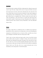
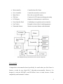
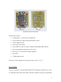
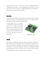
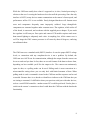
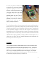
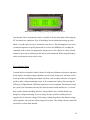
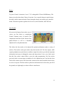
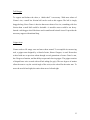
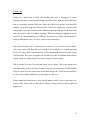
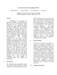
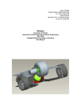
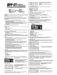
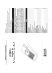
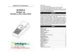
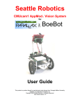
Student Name: William Dubel
TA : Uriel Rodriguez
Louis Brandy
Instructor. A. A Arroyo
University of Florida
Department of Electrical and Computer Engineering
EEL 5666
Intelligent Machines Design Laboratory
Final Report
Gizmo
A Line-Tracking Can-Moving Robot
1
Table of Contents
I.
II.
III.
Introduction
3
Purpose
3
Environment
4
Design
4
Electronics
5
Microcontroller
5
Servo Controller
6
Motor Driver
7
CMUcam
7
LCD Display
9
Power Interface Panel
10
Battery
11
Line Tracker
11
Ultrasound Sensors
12
Mechanics
12
Drive Motors
12
Tail Dragger
13
Gripper Arm
13
IV.
Conclusions
14
V.
Photograph Images
15
VI.
Footnotes
16
VII.
References
17
IIX.
Appendix A: Source Code
19
2
Introduction:
This paper describes a robot that will follow a high contrast line, looking for empty soda
cans in its path. The robot will place all blue cans to the right, and all other cans on the
left. It requires the use of an arm, a line tracker, ultrasound, and a color vision sensor. The
robot is named Gizmo, because it has quite an assortment of sensors and moving parts in
a small package. Gizmo can differentiate colors, as well as center its arm on an object.
Both of these tasks are accomplished with a CMUcam, which is the special sensor on
Gizmo. The CMUcam is a color vision sensor. It is a small CCD1 camera mated with a
microcontroller capable of simple image processing. Although limited in its abilities, the
CMUcam provides Gizmo with the necessary information to track and differentiate
objects of color.
Purpose:
The purpose of this robot is to simulate the task of a warehouse style robot that is
programmed to follow a particular route collecting objects on its route and handling them
appropriately. It will demonstrate the use of sensors to follow a specified route and some
type of intelligence to determine what to do with any objects it finds.
Gizmo’s task is to locate colored cans along its path. In the real world, this decision
process could be used to sort parts in a warehouse or factory, where the parts would be
taken to their next destination for processing. The purpose of the vision sensor is to detect
the color of the can, as well as to provide positioning information for the robot to center
its arm on the can. Since only one camera will be used it will be difficult to establish the
distance from the can. The robot will rely on a separate ultrasound sensor for that
information, as well as the presence of a can in the first place.
3
Environment:
The environment for Gizmo will be a typical classroom or warehouse floor. The floor
will be marked with a high contrast line. Gizmo will expect a black line on white floor. It
may be reprogrammed for the opposite as well. The environment should be free from
unknown materials (except empty soda cans). The soda cans to be processed will be
placed on Gizmo’s path, somewhere on the black line it is to follow. The soda cans
should be predominantly one color or another, as that is what the sensor will be capable
of detecting. Some good cans to use are the Classic Coke, Sprite, Pepsi (although it has
some red in it), and most of the Wal-Mart (Sam’s) brand cans.
Design:
Gizmo was designed on a computer to make assembly quick and its pieces easy to
replicate. Reliability is a primary design criterion, so that most of the work will be in its
programming. To achieve this, all boards are PCB2 (no breadboards, wire-wrap, etc).
Polycarbonate is used for all the cut layers, and its pieces are laser cut. Glue is avoided as
much as possible. Standard geared DC motors will be used in place of modified servos.
The robot can be reprogrammed (without disassembling anything) through a serial port.
The primary microcontroller will be either the PIC16F877 or PIC18F452. C will be the
language of choice, although assembly is always available. Gizmo will make use of
ultrasound sensors, infrared sensors, a color vision sensor (CMUcam), a keypad, an LCD
display, and a gripper arm, to accomplish its tasks.
Electronics:
Gizmo has many electronic subsystems. Each component is a modular board designed to
work not just in Gizmo, but other robots as well. The electronic components of Gizmo
consist of the following:
4
•
Microcontroller
Controller board for Gizmo
•
Servo Controller
Controls the motor driver and servos
•
Motor Driver
Drive the two main DC motors
•
CMUcam
Consists of a CCD camera and image processing
•
LCD Display
Outputs user information to a small screen
•
Power Interface Panel
Combined power regulation and user interface
•
Line Tracker
Designed to detect a line for tracking purposes
•
Ultrasound Sensors
Sensors to measure distance with ultrasound
Block Diagram showing connections between the electronic components
Microcontroller
I designed the microcontroller board specifically for small robots just like Gizmo. It
features a socket for any 44-pin PLCC Microchip microcontroller. However, I’ve
designed it with the PIC16F87x and PIC18F4xx series in mind, because of their
compatibility with bootloader3 software.
5
Top and bottom of microcontroller board
The board also features:
•
6 analog inputs – can also be used as digital I/O
•
4 powered ports for separate ultrasound distance sensors
•
12 spare digital I/O pins
•
Powered I2C4 Bus Master
•
Powered RS2325 transceiver (up to 300kbps) with standard DB9 connector
•
Extra serial transmitter (9600 bps) at TTL6 levels
•
Precision 5.0 V current-limited voltage regulation
•
Status LED
•
3 additional power taps
The board is small enough for the most petite robots, at just 2.0” x 2.5”.
Servo Controller
The servo controller is a Scott Edwards Mini SSC II designed to control up to 8 servos.
It’s small and works well for most robots. When the controller is powered, it immediately
6
turns on and centers all servos. It would be nice if the servo controller waited until a
command is sent to move that servo. This centering behavior causes Gizmo’s arm to jerk
unnecessarily on reset. This would be a simple programming fix, but unfortunately, I
don’t have the source code for the servo controller.
Motor Driver
The motor driver is a SOZBOTS Dual Speed Board. The board takes two RC7 compatible
PWM8 signals and drives two bi-directional DC motors. I have no complaints with this
board, and recommend it to anyone using small DC motors.
The board handles up to 5 A per motor,
continuous 500 mA, and works with voltages
from 6 V to 18 V. Gizmo’s two small DC
geared motors connect directly to the motor
driver, as does the unregulated voltage from
its battery. The servo controller, to control
the left and right motors, provides the two
PWM signals.
SOZBOTS Dual Speed Board
CMUcam
The CMUcam as an image-processing device makes for an inexpensive color sensor, at
about $109. Not only can it detect the presence of a particular color, but the CMUcam
also reports back the level of confidence it has that the color is present, and the center of
that presence. It is also small enough for a desktop robot, although the attached
processing board could be smaller. I find that the camera’s image processing software has
been programmed well, given the constraints of the processor hardware.
7
While the CMUcam usually does what it’s supposed to, its slow, limited processing is
obvious to the user. Lowering the baud rate slows down all the processing. Since the only
interface is RS232, many devices cannot communicate at the camera’s fastest speed, and
performance suffers. I2C is not available. Poorly designed hardware will frustrate most
users and components frequently come improperly soldered. Large through-hole
components are crammed together under constant stress. The regulator, which sticks off
of the board, is unsecured, and overheats with the supplied power adapter. If you touch
the regulator it will burn you. Poor optics and camera CCD module requires much more
than normal lighting to adequately track color. At anything less, all the camera sees is
red. The image the CMU camera processes is off center by about 10 degrees, confusing
un-calibrated robots.
The CMUcam uses a standard serial (RS232) interface. It uses the proper RS232 voltage
levels, so connection with any compliant device is not a problem. By default, the
CMUcam uses ASCII text for communication, although the output from the camera can
be set to send raw byte data. In fact, there are several formats of the data to choose from,
depending on how readable you’d like the output to be. The camera can continuously
report its data, or a polling mode can be used. Polling mode is most convenient in a
microcontroller setting where you can only deal with limited amounts of data. When
polling mode is used a command is issued to the CMUcam and the response can be read
as needed. Because there is no header or identifier to indicate to the CMUcam that you
are issuing a command, it’s difficult to share your precious serial port with other devices,
such as a serial PWM controller - another reason I2C would be preferred. I had to place a
switch on the camera’s connection so that I could share the CMUcam with the bootloader
functionality.
8
To remedy the problem the CMUcam has
not detecting color under normal lighting,
supplemental lighting for Gizmo was
necessary. I created a special mount for the
vision sensor, which will not only house
the CMUcam and its complementary
ultrasound sensor, but also an array of
lights to illuminate the object detected by
ultrasound. This allows the camera to
distinguish color under any type of
lighting, including total darkness.
CMUcam, ultrasound, and LED light array mounted
To avoid reading stray objects, the camera mount aims the camera towards the ground, so
that the field of view of the robot is limited to the area under the height of the robot.
Using this mount should fix most of the problems with the poor optics. Contending with
the slow performance response is still an issue, and I will have to be careful in my
programming to give the CMUcam ample time to respond. The automatic white balance
and gain takes about 6 seconds to adjust, and I need to decide if I should do an initial
calibration with no objects (preferably on startup), calibrate on the first object I see, or
calibrate on every object. This time consuming adjustment would significantly slow
down the operation of Gizmo if required.
LCD Display
The LCD display on Gizmo is a Matrix Orbital LK162-12 serial 16x2 display. It has a
backlight, connection for keypad, and works with either RS232 or I2C. I interface the
display on I2C, and connect my keypad on the Power Interface to the display for user
input. I have few complaints with Matrix Orbital’s line of displays. They constantly
improve their line, and while they are relatively expensive – $30 with student discount,
the functionality and quality they bring are worth the cost.
9
Matrix Orbital LK162-12 Display presenting a program menu for the user
One bug that I have encountered is that it’s possible to freeze the display when using the
I2C bus under two conditions. First, if the display has not finished powering up (takes
about ¼ second) and you issue a command, it may freeze. This also happens if you issue
a command sequence to quickly that needs to write to its EEPROM as it’s reading the
command, such as when you program the startup screen. The solution is a delay in both
instances, but it can be confusing as this bug is not documented. When using the display
on the serial interface there are no issues.
Power Interface Panel
I created the Power Interface Panel to house all of the miscellaneous electronics that most
robots require, including voltage regulation, power switch, charge jack, and reset switch.
It also provides useful things most robots could use, such as status indicators, a keypad, a
speaker, and a voltage monitoring circuit. It also contains the circuitry for powering the
LED array of lights that the CMUcam requires for color recognition. The interface board
isn’t pretty, but it eliminates the need for extra electronic boards and devices. I’ve made
three of these boards (including this one). One problem I have with this board is my
design for voltage monitoring. It uses a voltage divider, and relies on the precision
regulator for its reference voltage. If the battery voltage drops below the dropout voltage
on the regulator, the reference will no longer be accurate. The voltage reference should be
provided by a zener diode instead.
10
Battery
To power Gizmo’s electronics, I use a 7.2 V rechargeable 1550 mA NiMH battery. The
battery gives the robot about 2 hours of run time. I use a special charger to quick charge
the battery while connected inside Gizmo, through a charge jack on the power interface
board. Gizmo has separate regulators for its servos, microcontroller, and CMUcam.
Line Tracker
My soon-to-be-famous line tracker was, of
course, my first choice to complement
Gizmo’s fantastic array of sensors! The
comparator based line tracker features four
photo-reflectors as well as a threshold
adjustment for each phototransistor.
This allows the line tracker to be adjusted for optimal performance under a variety of
surfaces. This tracker works great where many line trackers fail. The four outputs, while
requiring slightly more pins than two and three output line trackers, provide the important
information necessary to distinguish corners and intersections. I have yet to find a track
that this line tracker cannot follow, given the right programming. My line tracker
previously had an inconvenient orientation for the adjustment pots, but that has been
fixed in the current version. The line tracker connects to the microcontroller board, where
it receives its power. The line tracker is placed on the bottom level of the robot, just off of
the ground, at a slight angle, to reduce reflective interference.
11
Ultrasound Sensors
Gizmo makes use of three Devantech SRF04 UltraSonic Range Finders to detect
obstacles, and to help it navigate. The ultrasound sensors are accurate to about half an
inch, and can report ranges from 1 inch to 10 feet. The sensors work by emitting an
ultrasound sound pulse, and holding a line high until that pulse returns. Given the speed
of sound at sea level, and the time the echo line is high, a distance can be calculated.
One of the sensors is directed forward, and the other
two are directed about 30 degrees forward of the
robot’s perpendicular. Up to four SRF04 UltraSonic
sensors connect directly to my microcontroller board.
Mechanics
Gizmo’s mechanics require a mobile platform to precisely track lines and avoid
obstacles. Gizmo is heavier than most robots of its size. For reliable operation, Gizmo
uses two rugged DC geared motors, and a small tail dragger. Gizmo also has an arm to
perform the work of moving cans in its path out of the way.
Drive Motors
The drive motors are DC geared motors, available from Lynxmotion or Jameco, among
other places. They are standard 4 mm shaft 180-RPM motors. They have a good amount
of torque, but can still turn quite fast. The motors are rugged and will probably last many
years of usage – unlike modified servos. The motors connect directly to the motor driver.
12
Tail Dragger
To support and balance the robot, a “third-wheel” is necessary. With most robots of
Gizmo’s size, a small low friction ball can be used as this support. The ball is simply
dragged along. Since Gizmo is heavier than most robots of its size, something with less
friction than a small ball would be desirable. A movable caster would be too heavy.
Instead a tail dragger wheel like those used in small model aircraft is used. It provides the
necessary support with minimal drag.
Gripper Arm
Gizmo needs to lift empty cans and move them around. To accomplish its can-moving
task, a gripper arm designed by a friend of mine, Hector Gongora, is used. Hector has
worked with me on previous robots through several generations of arms. Gizmo’s arm,
has 2 degrees of motion, and the ability to open and close its gripper. The gripper consists
of shaped brass wire covered with soft fuel tubing (for grip). The two degrees of motion
allow the arm to vary the vertical angle of the wrist, as the robot lifts the entire arm. To
move the arm left and right, the entire robot moves left and right.
13
Conclusions:
Gizmo was a great robot to build, and watching him work is fascinating. It makes
mistakes sometimes, but poor programming is usually at fault. With this robot I had some
time to experiment with the CMUcam. While the CMUcam is not the best choice for
complex vision processing, the CMUcam does work for the simple task of locating and
sorting objects of color. It also has some additional functions that may be useful in other
tasks for Gizmo, such as window tracking. With the additional lighting and time
necessary for auto adjustment, the CMUcam should provide Gizmo the information it
needs to differentiate colors, as well as center its arm on an object.
This is the first robot that I’ve had the pieces laser cut. I’ve previous cut them with a
CNC router, and also by hand. The laser cutting is well worth the cost – which was about
$43 for this robot. There is almost no kerf, so no compensation needs to be made in your
CAD drawings. The pieces fit together so well that I was able to eliminate almost all use
of glue. I plan on sending out all of my future designs for laser cutting.
This is also the first robot I’ve made that’s truly easy to charge. This is due in part to the
accessible charge jack on the Power Interface, and also due to the use of a NiMH battery.
However, most of its ease comes from an excellent charger, the Triton from Great Planes.
For the serious robotics enthusiast, a good charger is a life saver.
Gizmo should also function as a more general purpose robot. I plan to add some new
features to the robot, such as a hall effect compass, a faster processor, and an improved
gripper arm.
14
Gizmo the Robot, performing its power up test
Gizmo’s laser cut pieces before assembly
15
Footnotes:
1.
CCD stands for charge-coupled device, but is used to describe a standard
imaging chip used in most low cost cameras. Web cams, digital cameras, and
camcorders all make use of a CCD.
2.
A printed circuit board, or PCB, is a permanent circuit etched or cut out of a
copper clad board. Because it’s permanent, it’s less likely that a connection
would be inadvertently broken.
3.
A bootloader is microcontroller code that can write to its own program
memory. These are usually used to allow new programs to be loaded into its
program area without a special device programmer.
4.
I2C (pronounced “eye squared see”) is a synchronous serial protocol that
operates on TTL levels and has provision for bi-directional communication
between up to 127 (with 7 bit addressing) devices. It requires an SCL and
SDA line, as well as a ground connection. The bus is externally pulled high
via a resistor.
5.
RS232 is a recommended standard for serial communications, and at one time
was found on most desktop computers. It defines a signal that uses between –
25 V and –3 V for a logic 1 transmission, and between +3 V and +25 V for
logic 0. It is a legacy standard that is usually modified for its application. At a
minimum it requires separate TX and RX lines, as well as a ground
connection.
6.
TTL stands for transistor-transistor logic, but is used in this document to
describe voltage levels of 0 V and 5 V, with threshold values at 0.8 V and 2 V.
7.
RC stands for Radio Control. It is usually used to indicate that a particular
electronic device, such as a servo controller or motor driver, work with a
standard pulse width range of about 0.5 ms to 2.5 ms, at about 50 Hz.
8.
Pulse Width Modulation, or PWM, is a type of signal modulation used to
transmit an analog signal on a channel with two possible values. The PWM
signals in this document use standard RC servo ranges.
16
References:
CMUcam Vision Board User Manual. Anthony Rowe and Carnegie Mellon University.
Version 1.15, 2002 http://www.seattlerobotics.com/cmucam.htm
Microchip PIC 16F877. Microchip Corporation, Updated April 2003
http://www.microchip.com/1010/pline/picmicro/category/embctrl/14kbytes/devices/16f8
77/
HiTech Compiler Manual. HiTech Software, Copyright 2002
http://www.htsoft.com/products/piclite/index.html
Microchipc (bootloader code and schematic). Shane Tolmie, Copyright 2003
http://www.microchipc.com/PIC16bootload/
Gear Head Motor Datasheet. LynxMotion, Copyright 2000
http://www.lynxmotion.com/ghm02.htm
An Autonomous Firefighting Robot. W. Dubel, H. Gongora, K. Bechtold, D. Diaz, and
Florida International University. FCRAR 2003
Mini SSC II Serial Servo Controller. Scott Edwards Electronics, Inc., Copyright 1999
http://www.seetron.com/pdf/ssc2_mnl.pdf
LK162-12 User Manual. Matrix Orbital, Copyright 2003
http://www.matrixorbital.com/manuals/LK162-12_03.pdf
Devantech SRF04 UltraSonic Range Finder. © 1994-2003, Acroname Inc.,
http://www.acroname.com/robotics/parts/R93-SRF04.html
17
Nickel Metal Hydride Individual Data Sheet. Panasonic, February 2002
http://www.panasonic.com/industrial/battery/oem/images/pdf/Panasonic_NiMH_HHR16
0AA_B.pdf
Hitech Servo Specification Sheets. Hitech RCD USA, Inc.
http://www.hitecrcd.com/Servos/hs85mg.pdf
http://www.hitecrcd.com/Servos/hs55.pdf
18
Gizmo the Robot
Source Code
Compiled with the HiTech PICC compiler for the Microchip PIC16F877
19