1
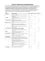
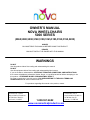
OWNER’S MANUAL
NOVA WHEELCHAIRS
5000 SERIES
(5060,5080,5090,5160,5180,5165,5185,5190,5195,5200)
OWNER
YOU MUST READ THIS MANUAL BEFORE USING THIS PRODUCT
DEALER
YOU MUST SUPPLY THE OWNER WITH THIS MANUAL
WARNINGS
DO NOT
Use this product without first reading and understanding this manual.
DO NOT
Use this equipment without first reading and understanding Nova’s terms.
If you are unable to understand the, CAUTIONS, TERMS AND CONDITIONS, AND INSTRUCTIONS,
then contact a healthcare professional, dealer, lawyer, or a qualified technician before attempting to use
this product - OTHERWISE INJURY OR DAMAGE MAY RESULT.
By using or continuing to use this product, YOU ARE AGREEING TO THE NOVA TERMS AND
CONDITIONS detail at www.novaortho-med.com.
For questions regarding this manual or the product, contact
Distribution center:
Nova Medical Products
8730 West 50th St.
McCook, IL 60525
1-800-557-6682
www.novamedicalproducts.com
Corporate Office
Nova Medical Products
1470 Beachey Pl.
Carson, CA 90746
COMMON PART LOCATIONS
Armrest
Back Upholstery
Seat Upholstery
24” Wheel w/Rim
Foot Rigging
Wheel locks
8” Castor
Foot Plate
OPERATING INSTRUCTIONS
SERVICE
All service must be performed while the wheelchair is unoccupied.
Minor adjustments may be attempted by an able bodied individual. All minor adjustments that one should
attempt are detailed in the manual. Do not attempt any adjustment or repair without reading and
understanding the instructions in this manual. Do not attempt any adjustment or repair that is not detailed
in this manual. Any adjustment or repair not detailed in this manual should only be preformed by a dealer
or licensed technician.
Individuals with muscular or balance problems should not attempt to make adjustments to the product,
and are advised to seek assistance.
After any adjustment, and before using the product, ensure that all attaching hardware, including without
limitation all grips, screws, nuts, bolts, clamps, fasteners, and parts are tight and secure.
DO NOT use parts, accessories, or adapters other than those manufactured by Nova Ortho Med., Inc,
which are designed specifically for this product.
PROPER USE
OPENING CHAIR
Tilt wheelchair to one side and push down on the seat rail until fully opened.
CLOSING CHAIR
Fold footrests to the closed/vertical position. Tilt product to one side and lift up on seat rail until fully
closed.
ALWAYS
- ensure that all grips and textured surfaces are secure before pushing, pulling, or placing weight on such
surfaces.
- perform the initial product inspection and all follow-up inspections before using the product.
DO NOT
- sit on product unless the product is fully open and in it’s normal usable position.
- use ramps or operate the product on inclines greater than 9 degrees of slope.
- operate on moving walkways, escalators, roads, streets, or highways (Use extreme caution when
operating product in crowded areas or outdoors).
DO NOT (continued) - operate product in bad weather or when ground conditions may impair traction,
such as ground with water, oil, ice, gravel, or any other slippery or unstable substance.
- attempt to cross curbs, bumps, trenches, or other uneven surfaces. Doing so may tip over the product.
Operate product only on smooth well-maintained surfaces.
- attempt to reach objects while using product as this requires you to move your weight, and can cause
the product to tip over.
- reach for objects, as this requires you to move your weight, and can cause the product to tip over.
- pick up objects from the floor, as this requires you to move your weight, and can cause the product to tip
over.
- tilt the wheelchair while occupied.
- use the wheel locks as brakes, nor attempt to stop a moving product be engaging the wheel locks.
- attempt to lift the product by lifting any removable part or surface.
- stand on the product, the product frame, or any other part of the product.
- use the footrests as a platform. When attempting to enter or exit the product, ensure that the footrests
are in the upward, unusable position.
- carry heavy weight while occupying the product. The product is not designed for additional weight, and
is not balanced to accommodate additional weight.
- lift weights or exercise while occupying the product.
ENTERING AND EXITING PRODUCT
Ensure that there is as little space as possible between the occupant and product when attempting to
enter or exit the product. ALWAYS ensure that the wheel locks are engaged when entering and exiting
product. When attempting to enter or exit the product, ensure that the footrests are in the upward,
unusable position.
MOVING THE PRODUCT
ALWAYS use the wheel hand rims for self-propulsion. If your product does not have hand rims, then
have someone assist you by pushing the product using the handgrips design for that use.
REMOVING ARMREST
Remove arms by depressing spring button and lifting arms out of front and rear sockets.
SAFETY INSPECTION- MAINTENANCE
Your product is a precision product - proper care will ensure proper function. Regular cleaning will reveal
loose or worn parts. DO NOT over tighten parts or hardware, as doing so can damage the frame. DO
NOT operate the product if there are any missing parts or hardware. You should have a dealer or
qualified professional perform maintenance on your product at least once every six months, or
immediately if you notice any item needing service. Frequent use likely means that your product will
require more maintenance than we suggest. In anticipation of and after any excessive use, we
recommend that you perform a complete safety inspection including all items.
IT EM
G E N E R AL
IN S PE C T IT EM
IN IT IAL W E EK
W heelchair should roll straight, doesn't feel "tight"
or pull to one side
X
X
Inspect for loose, m issing, or brok en hardw are in
all locations
X
Inspect for bent fram e
X
F R AM E
Inspect w eld points for crack s, chips, or loose
m aterial
X
X
C R O S S-B R AC E S Inspect for bent cross-braces
Inspect w eld points for crack s, chips, or loose
m aterial
X
Ensure lock s do not interfere w ith tires w hen
W H E EL L O C K S
rolling
X
X
Pivot points free of w ear and looseness
X
W heel lock s are easy to engage, and engage
fully
X
X
W heel lock s prevent w heelchair from m oving
w hen engaged.
X
X
X
S EAT AN D B AC K Inspect upholstery for rips or sagging
Inspect for loose or brok en hardw are
X
Inspect cane hand grips for w ear, looseness, or
deterioration
X
T IR E S
Inspect for correct and equal pressure
X
Inspect for crack s and w ear
X
Lift, spin, and check for side m ovem ent, rubbing,
R EAR W H EE L S
or binding
X
Inspect for correct and equal pressure
X
Inspect for crack s and w ear
X
H AN D R IM S
Inspect for signs of rough edges or peeling
X
FRONT FORKS
C LE AN IN G
Inspect w heel/fork assem bly for proper tension by
spinning caster. C aster should com e to a gradual
stop, and not bind or grind
Adjust bearing system if w heel w obbles
noticeably or binds to a stop
Ensure w heel bearings are clean and free of
m oisture
C heck head tube lock nuts for tightness
Inspect casters for crack s and w ear (hubs and
rim s)
Inspect for crack ed or brok en spok es
C lean upholstery and arm rests
M ONTH
X
X
X
X
X
X
X
X
X
X
X
X
X
X
X
X
X
X
X
X
X
X
X
6 M ONTH
X
X
X
X
FOOT REST ASSEMBLY
INSTALLING LEG REST
1 - Hold the foot assembly in position as if it were in position for use.
2 - Turn the front foot assembly to the side (so that open foot plate, which was perpendicular to the wheel,
is now parallel with the wheel).
3 - Slightly raise the assembly and place the hinge plates on the front foot assembly onto the hinge pins
on the product frame.
4 - Rotate the foot assembly inward, toward the inside of the wheelchair until it locks into place (so that
the foot plate is perpendicular with the wheel).
5 - Repeat for other foot assembly.
REMOVING LEG REST
1 - Push the release lever inward.
2 - Rotate the front foot assembly to the side (so that open foot plate, which was perpendicular to the
wheel, is now parallel with the wheel).
3 - Slightly lift the foot assembly so that it comes off the hinge pins.
ADJUSTING LEG REST HEIGHT
1 – RELEASE the tension screw by turning counter clockwise
2 - PRESS the leg rest release push buttons.
3 - Adjust the leg rest to the proper height.
4 - Ensure that the leg rest release button re-engages (push-buttons click in place).
5 – TIGHTEN tension screw by turning counter clockwise
SEAT
ADJUSTING SEAT HEIGHT
DO NOT ATTEMPT – Please see a dealer or qualified technician.
Any adjustment in your product seat can affect the stability of your product. We HIGHLY recommend that
you have a dealer or licensed technician adjust your seat height to ensure that your adjustments are safe
given your condition, and your product. Seat adjustments affect other parts of your product, including
without limitation, the adjustment of your anti-tipping supports, the necessary size and position of your
forks, the necessary size and position of your rear wheels, and the size and position of safety devices,
such as straps, locks, etc.
If you raise your seat height YOU MUST purchase proper anti-tipping supports. If your product came with
anti-tipping supports, then they are not likely to work with your new seat adjustment, and you must buy
new, proper supports.
REPLACING SEAT UPHOLSTERY
1 - The seat upholstery is held in place by eight Philips screws and washers, attached to the horizontal
bars on the product seat.
2 - Remove the screws, replace upholstery, and reattach screws.
REPLACING BACK UPHOLSTERY
1 - The back upholstery is held in place by eight Philips screws and washers attached to the upright bars
on the product back.
2 - Remove the screws, replace upholstery, and reattach screws.
WHEELS
Solid rubber tires need minimal maintenance, but should be cleaned occasionally with a damp cloth.
Replace if tires become severely worn or cracking appears.
REPLACING TIRES
DO NOT ATTEMPT – Please see a dealer or qualified technician.
REMOVING AND REPLACING REAR WHEELS
1 - Remove dust cap (if any).
2 - Remove attachment bolt and related hardware (washer, spacers) that hold the wheel in place.
3 - If replacing wheel, reverse above steps, and then continue with step 4.
4 - Tighten attachment bolt with torque wrench, to 40 ft.-lbs.
5 - Adjust wheel locks to ensure proper wheel lock function.
6 - Rotate (or spin wheel) to ensure proper fitting and alignment. Wheel should not wobble, grind, or
catch.
REPLACING HAND RIM
1 - Remove the rear wheel from the wheelchair before attempting to replace hand rim, see Removing and
Replacing Rear Wheels, above.
2 - Remove the mounting screws and washers that secure the hand rim to the rear wheel, and remove
the hand rim.
3 - Align new hand rim so that the holes in hand rim line up with the holes in the rim, and replace
mounting screws and washers.
REMOVING AND REPLACING FRONT WHEEL
DO NOT change wheel sizes. Your product is design for a specific size wheel, and your forks will not
safely accommodate larger or smaller wheels.
1 - Remove attachment bolt and attachment hardware (washer, locknut, spacer, etc).
2 - Remove old wheel.
3 - Line up new wheel to ensure that you use same frame holes as the old wheel used.
4 - Replace attachment bolt and attachment hardware (washer, locknut, spacer, etc).
5 - Rotate (or spin wheel) to ensure proper fitting and alignment. Wheel should not wobble, grind, or
catch.
REPLACING TIRE
DO NOT ATTEMPT - Please see a dealer or qualified technician.
WHEEL LOCKS
ADJUSTING WHEEL LOCKS
DO NOT operate wheels locks while the product is moving. DO NOT attempt to stop the product using
wheel locks (wheel locks are not brakes).
1 - Disengage locks.
2 - Loosen the bolt and locknut that secure the wheel lock to the frame.
3 - Reposition the wheel lock so that if it were engaged, the lock would press against the tire and depress
it 1/8th inch.
4 - Securely tighten the bolt and locknut attaching the wheel lock to the frame.
5 - Engage wheel lock and test to ensure that product does not move, and wheel does not turn, when
pushed.
6 - If product moves with locks engaged, then repeat above steps and slightly increase the amount that
lock depresses tire when engaged.
ANTI-TIPPING SUPPORTS
We recommend that you use anti-tipping supports to enhance the safety of your product. If your product
did not come with anti-tipping supports, and safety is your concern, then consider purchasing this
additional item.
INSTALLING ANTI-TIPPING SUPPORTS
Specific anti-tipping supports are only useful with certain seat angles and heights. If you cannot properly
adjust the anti-tipping supports given your seat angle or seat height, then DO NOT use product - contact
a dealer or technician.
1 – Remove the rear frame tube cap
2 - PRESS the adjustment release pin on the anti-tipping support.
3 - Insert anti-tipping support into the tube (wheel facing downward, toward the floor) until the brass pin
locks into place
4 - Place the product upright on a flat surface.
5 - Anti-tipping supports should be 1 ½ to 2 inches off floor, or they must be adjusted to this height.
ADJUSTING ANTI-TIPPING SUPPORTS
1 - Place the product on a flat surface.
2 - PRESS the tip length adjustment button (near the tip of the support).
3 - Adjust the support length to achieve 1 ½ inch to 2 inch clearance between the anti-tipping support and
the surface.
4 - Ensure that the anti-tipping support is locked in place at desired length.
5 - If you cannot properly adjust length of the anti-tipping supports, then you do not have the correct
supports for your product – contact the dealer who sold you the anti-tipping supports and obtain correct
supports for your product.
REVIEW
THE MOST RECENT DOCUMENTATION
INCLUDING
PRODUCT TERMS AND CONDITIONS
AT
www.novamedicalproducts.com