1
Everything’s possible.
Analog Drives
for Servo Systems
Hardware
www.a-m-c.com
MNALHWIN-05
Installation Manual
Preface
ADVANCED Motion Controls constantly strives to improve all of its products. We review the information in
this document regularly and we welcome any suggestions for improvement. We reserve the right to modify
equipment and documentation without prior notice.
For the most recent software, the latest revisions of this manual, and copies of compliance and
declarations of conformity, visit the company’s website at www.a-m-c.com. Otherwise, contact the
company directly at:
ADVANCED Motion Controls • 3805 Calle Tecate Camarillo, CA • 93012-5068 USA
Agency Compliances
The company holds original documents for the following:
•
•
•
•
UL 508c, file number E140173
Electromagnetic Compatibility, EMC Directive - 2004/108/EC
EN61000-6-2:2005
EN61000-6-4:2007
Electrical Safety, Low Voltage Directive - 2006/95/EC
EN 60204-1:2006
Reduction of Hazardous Substances (RoHS), 2011/65/EU
Trademarks
ADVANCED Motion Controls™, the combined isosceles trapezoid/right triangle logo, DIGIFLEX®,
DIGIFLEX® Performance™ and DriveWare™ are either registered trademarks or trademarks of
ADVANCED Motion Controls in the United States and/or other countries. All other trademarks are the
property of their respective owners.
Related Documentation
•
MNALHWIN-05
Product datasheet specific for your drive, available for download at www.a-m-c.com.
ii
/
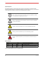
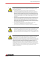
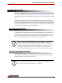
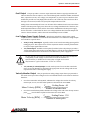
Attention Symbols
The following symbols are used throughout this document to draw attention to important operating
information, special instructions, and cautionary warnings. The section below outlines the overall directive
of each symbol and what type of information the accompanying text is relaying.
Note - Pertinent information that clarifies a process, operation, or easeof-use preparations regarding the product.
Note
Notice - Required instruction necessary to ensure successful completion
of a task or procedure.
Caution - Instructs and directs you to avoid damaging equipment.
Warning - Instructs and directs you to avoid harming yourself.
Danger - Presents information you must heed to avoid serious injury or
death.
Revision History
Document ID
Revision #
Date
Changes
MNALHWIN-01
1
9/25//2009
Analog Product Family Hardware Installation Manual First Release
MNALHWIN-02
2
5/13/2011
Discontinuation of B100A40, B100A40AC, B60A40, B60A40AC, B100A8, B100A20
MNALHWIN-03
3
5/30/2013
Addition of B060A400AC and B100A400AC
MNALHWIN-04
4
6/30/2013
Discontinuation of S60A8, S100A8, S100A40AC, SX30A8
MNALHWIN-05
5
1/13/2015
Discontinuation of 25A20DD,16A20AC, 25A20I, 30A20AC, 30A8DD, 50A20DD, 50A20I,
50A8DD, BD15A8, BD25A20AC, BD25A20I, BD30A8
© 2015 ADVANCED Motion Controls. All rights reserved.
iii
MNALHWIN-05
Contents
1
Safety
1
1.1 General Safety Overview . . . . . . . . . . . . . . . . . . . . . . . . . . . . . . . . 1
2
Products and System Requirements
4
2.1 Analog Drive Family Overview . . . . . . . . . . . . . . . . . . . . . . . . . . . . 4
2.1.1 Products Covered . . . . . . . . . . . . . . . . . . . . . . . . . . . . . . . . . 4
Drive Datasheet . . . . . . . . . . . . . . . . . . . . . . . . . . . . . . . . . . . 4
Standard and Custom Models . . . . . . . . . . . . . . . . . . . . . . . 5
2.2 Analog PWM Servo Drive Basics and Theory . . . . . . . . . . . . . . . . . 6
2.2.1 Single Phase (Brushed) Servo Drives . . . . . . . . . . . . . . . . . . 7
2.2.2 Three Phase (Brushless) Servo Drives . . . . . . . . . . . . . . . . . . 7
2.3 Power Stage Specifications . . . . . . . . . . . . . . . . . . . . . . . . . . . . . . . 9
2.4 Command Inputs . . . . . . . . . . . . . . . . . . . . . . . . . . . . . . . . . . . . . . 10
2.4.1 ±10V Analog . . . . . . . . . . . . . . . . . . . . . . . . . . . . . . . . . . . . . 10
2.4.2 PWM and Direction . . . . . . . . . . . . . . . . . . . . . . . . . . . . . . . 10
2.4.3 Sinusoidal . . . . . . . . . . . . . . . . . . . . . . . . . . . . . . . . . . . . . . . 10
2.5 Feedback Specifications . . . . . . . . . . . . . . . . . . . . . . . . . . . . . . . . 11
2.5.1 Feedback Polarity . . . . . . . . . . . . . . . . . . . . . . . . . . . . . . . . 11
2.5.2 Incremental Encoder . . . . . . . . . . . . . . . . . . . . . . . . . . . . . 11
2.5.3 Hall Sensors . . . . . . . . . . . . . . . . . . . . . . . . . . . . . . . . . . . . . . 12
2.5.4 Tachometer . . . . . . . . . . . . . . . . . . . . . . . . . . . . . . . . . . . . . 13
2.6 Modes of Operation . . . . . . . . . . . . . . . . . . . . . . . . . . . . . . . . . . . . 14
2.6.1 Current (Torque) Mode . . . . . . . . . . . . . . . . . . . . . . . . . . . . 14
2.6.2 Duty Cycle (Open Loop) Mode . . . . . . . . . . . . . . . . . . . . . 14
2.6.3 Hall Velocity Mode . . . . . . . . . . . . . . . . . . . . . . . . . . . . . . . 15
2.6.4 Encoder Velocity Mode . . . . . . . . . . . . . . . . . . . . . . . . . . . 15
MNALHWIN-05
iv
/
2.6.5 Tachometer Velocity Mode . . . . . . . . . . . . . . . . . . . . . . . .
2.6.6 Voltage Mode . . . . . . . . . . . . . . . . . . . . . . . . . . . . . . . . . . .
2.6.7 IR Compensation Mode . . . . . . . . . . . . . . . . . . . . . . . . . . .
2.6.8 Analog Position Loop Mode . . . . . . . . . . . . . . . . . . . . . . . .
2.7 System Requirements . . . . . . . . . . . . . . . . . . . . . . . . . . . . . . . . . . .
2.7.1 Analog Servo Drive Selection and Sizing . . . . . . . . . . . . .
Motor Current and Voltage . . . . . . . . . . . . . . . . . . . . . . . .
Motor Inductance . . . . . . . . . . . . . . . . . . . . . . . . . . . . . . . .
2.7.2 Power Supply Selection and Sizing . . . . . . . . . . . . . . . . . .
Power Supply Current and Voltage . . . . . . . . . . . . . . . . . .
Isolation . . . . . . . . . . . . . . . . . . . . . . . . . . . . . . . . . . . . . . . . .
Regeneration and Shunt Regulators . . . . . . . . . . . . . . . . .
Voltage Ripple . . . . . . . . . . . . . . . . . . . . . . . . . . . . . . . . . . .
2.7.3 Environmental Specifications . . . . . . . . . . . . . . . . . . . . . . .
Shock/Vibrations . . . . . . . . . . . . . . . . . . . . . . . . . . . . . . . . . .
3
Integration in the Servo System
3.1 LVD Requirements . . . . . . . . . . . . . . . . . . . . . . . . . . . . . . . . . . . . .
3.2 CE-EMC Wiring Requirements . . . . . . . . . . . . . . . . . . . . . . . . . . . .
General . . . . . . . . . . . . . . . . . . . . . . . . . . . . . . . . . . . . . . . . .
Analog Input Drives . . . . . . . . . . . . . . . . . . . . . . . . . . . . . . .
PWM Input Drives . . . . . . . . . . . . . . . . . . . . . . . . . . . . . . . . .
MOSFET Switching Drives . . . . . . . . . . . . . . . . . . . . . . . . . . .
IGBT Switching Drives . . . . . . . . . . . . . . . . . . . . . . . . . . . . . .
Fitting of AC Power Filters . . . . . . . . . . . . . . . . . . . . . . . . . .
3.2.1 Ferrite Suppression Core Set-up . . . . . . . . . . . . . . . . . . . . .
3.2.2 Inductive Filter Cards . . . . . . . . . . . . . . . . . . . . . . . . . . . . . .
3.3 Grounding . . . . . . . . . . . . . . . . . . . . . . . . . . . . . . . . . . . . . . . . . . . .
3.4 Wiring . . . . . . . . . . . . . . . . . . . . . . . . . . . . . . . . . . . . . . . . . . . . . . . .
3.4.1 Wire Gauge . . . . . . . . . . . . . . . . . . . . . . . . . . . . . . . . . . . . .
3.4.2 Motor Wires . . . . . . . . . . . . . . . . . . . . . . . . . . . . . . . . . . . . . .
3.4.3 Power Supply Wires . . . . . . . . . . . . . . . . . . . . . . . . . . . . . . .
DC Power Supplies . . . . . . . . . . . . . . . . . . . . . . . . . . . . . . . .
Single Phase AC Power Supplies . . . . . . . . . . . . . . . . . . . .
Three Phase AC Power Supplies . . . . . . . . . . . . . . . . . . . . .
3.4.4 Feedback Wires . . . . . . . . . . . . . . . . . . . . . . . . . . . . . . . . . .
Hall Sensors . . . . . . . . . . . . . . . . . . . . . . . . . . . . . . . . . . . . . .
Incremental Encoder . . . . . . . . . . . . . . . . . . . . . . . . . . . . . .
MNALHWIN-05
15
16
16
16
17
17
17
19
20
20
22
23
25
26
26
27
27
28
28
28
28
28
28
28
29
29
30
31
31
32
32
33
34
34
34
35
35
v
/
Tachometer . . . . . . . . . . . . . . . . . . . . . . . . . . . . . . . . . . . . . .
3.4.5 Input Reference Wires . . . . . . . . . . . . . . . . . . . . . . . . . . . . .
±10V Analog Input . . . . . . . . . . . . . . . . . . . . . . . . . . . . . . . .
Potentiometer Input . . . . . . . . . . . . . . . . . . . . . . . . . . . . . . .
PWM and Direction Inputs . . . . . . . . . . . . . . . . . . . . . . . . . .
Sinusoidal Input . . . . . . . . . . . . . . . . . . . . . . . . . . . . . . . . . . .
3.5 Mounting . . . . . . . . . . . . . . . . . . . . . . . . . . . . . . . . . . . . . . . . . . . . .
4
Operation
4.1 Initial Setup and Features . . . . . . . . . . . . . . . . . . . . . . . . . . . . . . .
4.1.1 Pin Function Details . . . . . . . . . . . . . . . . . . . . . . . . . . . . . . .
Current Monitor Output . . . . . . . . . . . . . . . . . . . . . . . . . . . .
Current Reference Output . . . . . . . . . . . . . . . . . . . . . . . . .
Inhibit Input . . . . . . . . . . . . . . . . . . . . . . . . . . . . . . . . . . . . . .
Continuous Current Limit Pin . . . . . . . . . . . . . . . . . . . . . . . .
Fault Output . . . . . . . . . . . . . . . . . . . . . . . . . . . . . . . . . . . . .
Low Voltage Power Supply Outputs . . . . . . . . . . . . . . . . .
Velocity Monitor Output . . . . . . . . . . . . . . . . . . . . . . . . . . .
4.1.2 Potentiometer Function Details . . . . . . . . . . . . . . . . . . . . .
Test Points for Potentiometers . . . . . . . . . . . . . . . . . . . . . . .
4.1.3 Switch Function Details . . . . . . . . . . . . . . . . . . . . . . . . . . . .
4.1.4 Adjustable Acceleration and Deceleration Rate . . . . . .
4.1.5 Tachometer Input Gain Scaling . . . . . . . . . . . . . . . . . . . . .
4.1.6 Current Limiting Procedure . . . . . . . . . . . . . . . . . . . . . . . . .
4.1.7 Drive Set-up Instructions . . . . . . . . . . . . . . . . . . . . . . . . . . .
Single Phase (Brush Type) . . . . . . . . . . . . . . . . . . . . . . . . . .
Three Phase (Brushless) . . . . . . . . . . . . . . . . . . . . . . . . . . . .
Three Phase (Brushless) Drive with Brushed Motor . . . . . .
Sinusoidal Drive (S-Series) . . . . . . . . . . . . . . . . . . . . . . . . . . .
4.1.8 Tuning Procedure . . . . . . . . . . . . . . . . . . . . . . . . . . . . . . . .
Current Loop Proportional Gain Adjustment . . . . . . . . . .
Current Loop Integrator Adjustment . . . . . . . . . . . . . . . . .
Voltage or Velocity Loop Tuning . . . . . . . . . . . . . . . . . . . .
Analog Position Loop . . . . . . . . . . . . . . . . . . . . . . . . . . . . . .
MNALHWIN-05
36
36
36
37
37
39
39
40
40
40
40
41
41
41
42
42
42
43
43
44
44
45
46
47
47
47
48
49
49
50
52
52
53
vi
/
A
Through-hole Component Tuning
A.1 Through-Hole Tuning . . . . . . . . . . . . . . . . . . . . . . . . . . . . . . . . . . .
A.1.1 Procedure . . . . . . . . . . . . . . . . . . . . . . . . . . . . . . . . . . . . . .
Tune the Current Loop Proportional Gain . . . . . . . . . . . . .
Tune the Current Loop Integral Gain . . . . . . . . . . . . . . . . .
Velocity Loop Integral Gain Tuning . . . . . . . . . . . . . . . . . .
B
Index I
MNALHWIN-05
Troubleshooting
B.1 Fault Conditions and Symptoms . . . . . . . . . . . . . . . . . . . . . . . . . .
Over-Temperature . . . . . . . . . . . . . . . . . . . . . . . . . . . . . . . .
Over-Voltage Shutdown . . . . . . . . . . . . . . . . . . . . . . . . . . .
Under-Voltage Shutdown . . . . . . . . . . . . . . . . . . . . . . . . . .
Short Circuit Fault . . . . . . . . . . . . . . . . . . . . . . . . . . . . . . . . .
Invalid Hall Sensor State (Brushless Drives only) . . . . . . . . .
Inhibit Input . . . . . . . . . . . . . . . . . . . . . . . . . . . . . . . . . . . . . .
Power-On Reset . . . . . . . . . . . . . . . . . . . . . . . . . . . . . . . . . .
B.1.1 Overload . . . . . . . . . . . . . . . . . . . . . . . . . . . . . . . . . . . . . . .
B.1.2 Current Limiting . . . . . . . . . . . . . . . . . . . . . . . . . . . . . . . . . .
Non-Foldback Current Limiting . . . . . . . . . . . . . . . . . . . . . .
B.1.3 Motor Problems . . . . . . . . . . . . . . . . . . . . . . . . . . . . . . . . . .
B.1.4 Causes of Erratic Operation . . . . . . . . . . . . . . . . . . . . . . . .
B.2 Technical Support . . . . . . . . . . . . . . . . . . . . . . . . . . . . . . . . . . . . . .
B.2.1 Product Label Description . . . . . . . . . . . . . . . . . . . . . . . . .
B.2.2 Drive Model Information . . . . . . . . . . . . . . . . . . . . . . . . . . .
B.3 Warranty Returns and Factory Help . . . . . . . . . . . . . . . . . . . . . . .
54
54
56
56
56
57
58
58
58
58
59
59
59
59
59
59
60
61
61
62
62
62
63
63
vii
1
Safety
This section discusses characteristics of your analog servo drive to raise your awareness of potential risks and
hazards. The severity of consequences ranges from frustration of performance, through damage to equipment,
injury or death. These consequences, of course, can be avoided by good design and proper installation into your
mechanism.
1.1 General Safety Overview
In order to install an analog drive into a servo system, you must have a thorough knowledge
and understanding of basic electronics, computers and mechanics as well as safety
precautions and practices required when dealing with the possibility of high voltages or heavy,
strong equipment.
Observe your facility’s lock-out/tag-out procedures so that work can proceed without residual
power stored in the system or unexpected movements by the machine.
You must install and operate motion control equipment so that you meet
all applicable safety requirements. Ensure that you identify the relevant
standards and comply with them. Failure to do so may result in damage
to equipment and personal injury.
Read this entire manual prior to attempting to install or operate the drive.
Become familiar with practices and procedures that allow you to
operate these drives safely and effectively. You are responsible for
determining the suitability of this product for the intended application.
The manufacturer is neither responsible nor liable for indirect or
consequential damages resulting from the inappropriate use of this
product.
High-performance motion control equipment can move rapidly with
very high forces. Unexpected motion may occur especially during
product commissioning. Keep clear of any operational machinery and
never touch them while they are working.
MNALHWIN-05
1
Safety / General Safety Overview
Keep clear of all exposed power terminals (motor, DC Bus, shunt, DC
power, transformer) when power is applied to the equipment. Follow
these safety guidelines:
•
•
•
•
•
•
•
Always turn off the main power and allow sufficient time for
complete discharge before making any connections to the drive.
Do not rotate the motor shaft without power. The motor acts as a
generator and will charge up the power supply capacitors through
the drive. Excessive speeds may cause over-voltage breakdown in
the power output stage. Note that a drive having an internal power
converter that operates from the high voltage supply will become
operative.
Do not short the motor leads at high motor speeds. When the motor is
shorted, its own generated voltage may produce a current flow as
high as 10 times the drive current. The short itself may not damage
the drive but may damage the motor. If the connection arcs or
opens while the motor is spinning rapidly, this high voltage pulse flows
back into the drive (due to stored energy in the motor inductance)
and may damage the drive.
Do not make any connections to any internal circuitry. Only
connections to designated connectors are allowed.
Do not make any connections to the drive while power is applied.
Do not reverse the power supply leads! Severe damage will result!
If using relays or other means to disconnect the motor leads, be sure
the drive is disabled before reconnecting the motor leads to the
drive. Connecting the motor leads to the drive while it is enabled can
generate extremely high voltage spikes which will damage the drive.
Use sufficient capacitance!
Pulse Width Modulation (PWM) drives require a capacitor on the high
voltage supply to store energy during the PWM switching process.
Insufficient power supply capacitance causes problems particularly with
high inductance motors. During braking much of the stored mechanical
energy is fed back into the power supply and charges its output
capacitor to a higher voltage. If the charge reaches the drive’s overvoltage shutdown point, output current and braking will cease. At that
time energy stored in the motor inductance continues to flow through
diodes in the drive to further charge the power supply capacitance. The
voltage rise depends upon the power supply capacitance, motor
speed, and inductance.
MNALHWIN-05
2
Safety / General Safety Overview
Make sure minimum inductance requirements are met!
Pulse Width modulation (PWM) servo drives deliver a pulsed output that
requires a minimum amount of load inductance to ensure that the DC
motor current is properly filtered. The minimum inductance values for
different drive types are shown in the individual data sheet
specifications. If the drive is operated below its maximum rated voltage,
the minimum load inductance requirement may be reduced. Most
servo-motors have enough winding inductance. Some types of motors
(e.g. "basket-wound", "pancake", etc.) do not have a conventional iron
core rotor, so the winding inductance is usually less than 50 μH.
If the motor inductance value is less than the minimum required for the
selected drive, use an external filter card.
MNALHWIN-05
3
2
Products and System Requirements
This chapter is intended as a guide and general overview in selecting, installing, and operating an analog servo
drive. Contained within are instructions on system integration, wiring, drive-setup, and standard operating
methods.
2.1 Analog Drive Family Overview
The analog drive family contains drives that can power Single Phase (Brushed) and Three
Phase (Brushless) motors. Analog drives are powered off either a single DC or AC power
supply, and provide a variety of control and feedback options. The drives accept either a ±10V
analog signal, a PWM and Direction signal, or two sinusoidal command signals as input. A
digital controller can be used to command and interact with analog servo drives, and a number
of input/output pins are available for parameter observation and drive configuration.
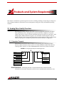
2.1.1 Products Covered
The products covered in this manual adhere to the following part numbering structure.
However, additional features and/or options are readily available for OEM’s with sufficient
ordering volume. Feel free to contact ADVANCED Motion Controls for further information.
FIGURE 2.1 Analog Product Family Part Numbering Structure
A
Motor Type
(blank): Brushed drive.
B or BX: Brushless drive.
Command Type
(blank): +/- 10 V Analog
DC: Torque Mode PWM
S or SX: Commutated Sine Wave
Feedback Type
(blank): Hall Sensors or None
E: Encoder and/or Hall Sensors
Peak Current
Maximum peak current rating in Amps.
Peak Voltage
Additional Options
ANP
H::
INV:
QD:
QDI:
Analog Position Loop
Available Hall Velocity Mode
Inverted Inhibit
Quick Disconnect
Quick Disconnect with
Inverted Inhibit
Power Supply
(blank): DC Power Supply
AC: AC Power Supply
FAC: AC Power Connecter
Located in the Front
Isolation Option
I: Optical Isolation
Peak voltage rating in Volts. If 2 numbers
used, scaled 1:10.
Drive Datasheet Each analog drive has a separate datasheet that contains important
information on the modes and product-specific features available with that particular drive,
MNALHWIN-05
4
Products and System Requirements / Analog Drive Family Overview
including the functional block diagram of the specific drive’s operation. The datasheet is to be
used in conjunction with this manual for system design and installation.
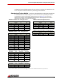
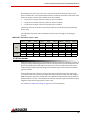
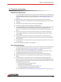
Standard and Custom Models The drives in the tables below are the standard product line
of ADVANCED Motion Controls’ analog servo drives. Note that not all possible part number
combinations from the product family numbering structure (Figure 2.1) are offered as
standard drives. Please contact ADVANCED Motion Controls’ Sales Department for further
information and details on custom drive solutions.
TABLE 2.1 Brushed ±10V Analog DC Drives
TABLE 2.5 Sinusoidal Input DC Drives
Drive Number
VDC
(Nominal)
Peak Current
(A)
Cont. Current
(A)
12A8
20-80
12
6
25A8
20-80
25
12.5
30A8
20-80
30
15
50A8
20-80
50
25
120A10
20-80
120
60
20A20
40-190
20
10
100A40
80-400
100
50
TABLE 2.2 Brushless ±10V Analog DC Drives
Drive Number
VDC
(Nominal)
Peak Current
(A)
Cont. Current
(A)
B15A8
20-80
15
7.5
BE15A8
20-80
15
7.5
BE15A8-H
20-80
15
7.5
B30A8
20-80
30
15
BE30A8
20-80
30
15
BX30A8
20-80
30
15
B25A20I
40-190
25
12.5
BE25A20I
40-190
25
12.5
BX25A20
60-200
25
12.5
B40A20I
40-190
40
20
BE40A20I
40-190
40
20
B30A40
60-400
30
15
B40A40
60-400
40
20
Drive Number
VDC
(Nominal)
Peak Current
(A)
Cont. Current
(Arms)
S16A8
20-80
16
8
SX25A20
60-190
25
12.5
S30A40
60-400
30
15
S60A40
60-400
60
30
S100A40
60-400
100
50
TABLE 2.6 Sinusoidal Input AC Supply Drives1
Drive Number
VAC
(Nominal)
Peak Current
(A)
Cont. Current
(Arms)
S30A40AC
45-265
30
15
S60A40AC
45-270
60
30
TABLE 2.3 Brushless ±10V Analog AC Drives1
Drive Number
VAC
(Nominal)
Peak Current
(A)
Cont. Current
(A)
B25A20AC
30-125
25
12.5
BE25A20AC
30-125
25
12.5
BX25A20AC
45-125
25
12.5
B30A40AC
45-265
30
15
B40A40AC
45-265
40
20
B060A400AC
200-240
60
30
B100A400AC
200-240
100
50
TABLE 2.4 Brushless PWM Input DC Drives
Drive Number
VDC
(Nominal)
Peak Current
(A)
Cont. Current
(A)
BDC30A8
20-80
30
15
BDC40A20
60-190
40
20
1.Certain AC drive models can also accept a DC power supply. Consult the drive datasheet to determine if DC input is allowed.
MNALHWIN-05
5
Products and System Requirements / Analog PWM Servo Drive Basics and Theory
2.2 Analog PWM Servo Drive Basics and Theory
Analog servo drives are used extensively in motion control systems where precise control of
position and/or velocity is required. The drive transmits the low-energy reference signals from
the controller into high-energy signals (motor voltage and current). The reference signals can
be either analog or digital, with a ±10 VDC signal being the most common. The signal can
represent either a motor torque or velocity demand.
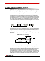
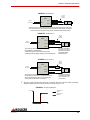
Figure 2.2 shows the components typically used in a servo system (i.e. a feedback system used
to control position, velocity, and/or acceleration). The controller contains the algorithms to
close the desired servo loops and also handles machine interfacing (inputs/outputs, terminals,
etc.). The drive represents the electronic power converter that drives the motor according to
the controller reference signals. The motor (which can be of the brushed or brushless type,
rotary, or linear) is the actual electromagnetic actuator, which generates the forces required to
move the load. Feedback elements are mounted on the motor and/or load in order to close the
servo loop.
FIGURE 2.2 Typical Motion Control System
Controller
Reference
Servo Drive
Current
Motor
Feedback
Load
Feedback
Although there exist many ways to "amplify" electrical signals, pulse width modulation (PWM)
is by far the most efficient and cost-effective approach. At the basis of a PWM servo drive is a
current control circuit that controls the output current by varying the duty cycle of the output
power stage (fixed frequency, variable duty cycle). Figure 2.3 shows a typical setup for a single
phase load.
FIGURE 2.3 PWM Current Control Circuit
+HV
S1
S2
D1
D2
I
Command
+
-
Current
Control
Motor
Switching
Logic
D3
Current Feedback
D4
S3
S4
Rc
S1, S2, S3, and S4 are power devices (MOSFET or IGBT) that can be switched on or off. D1, D2,
D3, and D4 are diodes that guarantee current continuity. The bus voltage is depicted by +HV.
The resistor Rc is used to measure the actual output current. For electric motors, the load is
typically inductive due to the windings used to generate electromagnetic fields. The current can
be regulated in both directions by activating the appropriate switches. When switch S1 and S4
(or S2 and S3) are activated, current will flow in the positive (or negative) direction and
increase. When switch S1 is off and switch S4 is on (or S2 off and S3 on) current will flow in
the positive (or negative) direction and decrease (via one of the diodes). The switch "ON" time
is determined by the difference between the current demand and the actual current. The
MNALHWIN-05
6
Products and System Requirements / Analog PWM Servo Drive Basics and Theory
current control circuit will compare both signals every time interval (typically 50 μsec or less)
and activate the switches accordingly (this is done by the switching logic circuit, which also
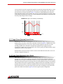
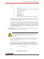
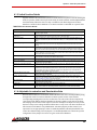
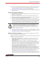
performs basic protection functions). Figure 2.4 shows the relationship between the pulse
width (ON time) and the current pattern. The current rise time will depend on the bus voltage
(+HV) and the load inductance. Therefore, certain minimum load inductance requirements are
necessary depending on the bus voltage.
FIGURE 2.4 Output Current and Duty Cycle Relationship
Current
ON time
Time
Pulse
width
2.2.1 Single Phase (Brushed) Servo Drives
Brushed type servo drives are designed for use with permanent magnet brushed DC motors
(PMDC motors). The drive construction is basically as shown in Figure 2.3. PMDC motors have
a single winding (armature) on the rotor, and permanent magnets on the stator (no field
winding). Brushes and commutators maintain the optimum torque angle. The torque
generated by a PMDC motor is proportional to the current, giving it excellent dynamic control
capabilities in motion control systems.
Brushed drives can also be used to control current in other inductive loads such as voice coil
actuators, magnetic bearings, etc.
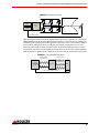
2.2.2 Three Phase (Brushless) Servo Drives
Three Phase (brushless) servo drives are used with brushless servo motors. These motors
typically have a three-phase winding on the stator and permanent magnets on the rotor.
Brushless motors require commutation feedback for proper operation (the commutators and
brushes perform this function on brush type motors). This feedback consists of rotor magnetic
field orientation information, supplied either by magnetic field sensors (Hall Effect sensors) or
position sensors (encoder or resolver). Brushless motors have better power density ratings
than brushed motors because heat is generated in the stator, resulting in a shorter thermal
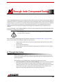
path to the outside environment. Figure 2.5 shows a typical system configuration.
MNALHWIN-05
7
Products and System Requirements / Analog PWM Servo Drive Basics and Theory
FIGURE 2.5 Brushless Servo System
+HV
S1
S2
S3
Current
Control
N
Switching
Logic
S
Commutation
Control
S1
S2
S3
Commutation Feedback
The commutation function can also be implemented in the motion controller, as in the case of
ADVANCED Motion Controls sinusoidal command input drives. The drive merely amplifies the
controller signals (2 analog sinusoidal signals that represent 2 of the 3 motor phase currents)
and creates the third motor phase current (the sum of the 3 currents must be zero) and
adjusts the phase angle to obtain maximum torque. No position feedback needs to be wired
into the drive. The motor current amplitude is proportional to the reference signal amplitude,
while the reference signal frequency depends on the motor velocity and the motor pole count.
FIGURE 2.6 Controller-based Commutation
Analog Sinusoidal
reference signals
Motor Currents
Controller:
Position Control
Velocity Control
Servo Drive
Motor
Commutation Control
Position and Commutation Feedback
MNALHWIN-05
Feedback
8
Products and System Requirements / Power Stage Specifications
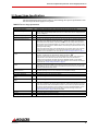
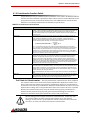
2.3 Power Stage Specifications
The drive datasheet lists the specific values for the following drive power specifications. Note
that not all specifications apply to every drive.
TABLE 2.7 Power Stage Specifications
Specification
Units
Description
DC Supply Voltage Range
VDC
Specifies the acceptable DC supply voltage range that the drive will operate within.
DC Bus Over Voltage Limit
VDC
Specifies the maximum DC supply voltage allowable. If the DC bus rises above the over voltage
limit, the drive will automatically disable, and will not re-enable until the DC bus voltage falls below
the over voltage limit.
AC Supply Voltage Range
VAC
Specifies the acceptable AC supply voltage range that the drive will operate within.
AC Supply Frequency
Hz
Specifies the acceptable frequency of the AC supply line.
Maximum Peak Output Current
A
Pertains to the maximum peak current the drive can output according to hardware limitations. An
RMS rating can be obtained by dividing this value by 2 . With the exception of S-series drives,
the maximum peak output duration is inherently limited to occur for no longer than 2 seconds, at
which point the current output will foldback over a period of 10 seconds to the continuous current
limit in order to protect the motor in stalled condition. Current limiting is implemented in the drive by
reducing the output voltage.
Most drive models feature peak current limit adjustments. The maximum peak current is needed
for fast acceleration and deceleration. Consult the drive datasheet to see which options are
available. For more information on the current limit see “Current Limiting Procedure” on page 46.
Maximum Continuous Output
Current
Maximum Continuous Sine Wave
Current
A
Pertains to the maximum continuous current the drive can output according to hardware
limitations. An RMS rating can be obtained by dividing this value by 2 .
Most drive models feature continuous current limit adjustments by the use of DIP switches or a
potentiometer. Some models also allow an external resistor to be connected between a
continuous current limiting pin and signal ground as an additional method of current limiting.
Consult the drive datasheet to see which options are available. For more information on setting the
current limit see “Current Limiting Procedure” on page 46.
Arms
Pertains to the maximum continuous RMS current that S-series (sinusoidal) drives can output
indefinitely. If the continuous RMS current output of the drive exceeds this value, the drive output
will be disabled. The drive will re-enable once the RMS current has returned to a level below the
maximum continuous sine wave current.
Maximum Power Dissipation at
Continuous Current
W
The power dissipation of the drive, assuming approximately 5% power loss to heat dissipation.
Calculated by taking 5% of P=V•I at continuous current and peak bus voltage.
Internal Bus Capacitance
μF
The capacitance value between the internal DC bus voltage and power ground.
Internal Shunt Resistance
W
The resistance value of the internal shunt resistor.
Internal Shunt Resistor Power
Rating
W
The power rating of the internal shunt resistor.
Internal Shunt Resistor Turn-on
Voltage
Minimum Load Inductance
VDC
μH
The turn-on voltage of the internal shunt resistor.
The minimum inductance needed at the output of the drive for proper operation. For a brushless
motor, this corresponds to the phase-to-phase inductance. If this minimum inductance is not met,
a filter card should be used to add additional inductance. Some motors may operate with slightly
less than the required inductance if the bus voltage is low enough. ADVANCED Motion Controls
provides various accessories including inductive filter cards for a wide range of drives. See
“Inductive Filter Cards” on page 29 for more information.
Shunt Fuse
A
The current rating of the internal shunt resistor fuse.
Bus Fuse
A
The current rating of the input AC line fuses.
Switching Frequency
MNALHWIN-05
kHz
The switching frequency of the drive output power stage.
9
Products and System Requirements / Command Inputs
2.4 Command Inputs
The input command source for analog servo drives can be provided by one of the following
options. Consult the drive datasheet to see which command source is available for a specific
drive.
2.4.1 ±10V Analog
A differential or single-ended ±10V analog reference signal can be used to command the drive
by adjusting the motor current, voltage, or speed, depending on the mode the drive is
operating in. For information on the proper wiring of a ±10V analog input, see “Input
Reference Wires” on page 36.
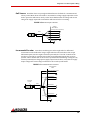
2.4.2 PWM and Direction
PWM and Direction Input is a specialized type of command that requires a compatible
controller. The controller needs two high speed TTL digital outputs to control these drives, one
for PWM and the other for Direction. The PWM duty cycle corresponds to the magnitude of the
output. Direct control of the PWM switching puts response times in the sub-microsecond
range. Since these drives don’t take analog inputs for command the need for a D/A converter
for drive control is eliminated. In Torque Mode PWM (e.g. "BDC" drives) the PWM input goes
into a PWM-to-Analog converter. The analog signal is then used as a command into the current
loop, resulting in a Current Mode drive controlled with PWM and Direction.
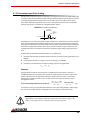
2.4.3 Sinusoidal
The "S-Series" of analog servo drives use sinusoidal input signals as the command input.
Sinusoidal Input is a specialized type of command that requires a compatible controller with
specialized commutation algorithms for proper operation. Two sinusoidal command signals
(120 degrees out of phase) from the controller control the commutation and torque of the
motor. The controller is effectively closing the current loop by controlling the torque angle (see
Figure 2.6). All feedback goes to the controller, not the drive, including commutation feedback.
This allows a wide variety of feedback options, limited only by the compatibility of the
controller.
MNALHWIN-05
10
Products and System Requirements / Feedback Specifications
2.5 Feedback Specifications
There are a number of different feedback options available in the family of analog drives. The
feedback component can be any device capable of generating a voltage signal proportional to
current, velocity, position, or any parameter of interest. Such signals can be provided directly
by a potentiometer or indirectly by other feedback devices such as Hall Sensors or Encoders.
These latter devices must have their signals converted to a DC voltage, a task performed by the
drive circuitry.
Consult a specific drive datasheet to see which feedback devices are available for that drive.
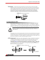
2.5.1 Feedback Polarity
The feedback element must be connected for negative feedback. This will cause a difference
between the command signal and the feedback signal, called the error signal. The drive
compares the feedback signal to the command signal to produce the required output to the
load by continually reducing the error signal to zero. This becomes important when using an
incremental encoder or Hall sensors, as connecting these feedback elements for positive
feedback will lead to a motor "run-away" condition. In a case where the feedback lines are
connected to the drive with the wrong polarity in either Hall Velocity or Encoder Velocity
Mode, the drive will attempt to correct the "error signal" by applying more command to the
motor. With the wrong feedback polarity, this will result in a positive feedback run-away
condition. To correct this, either change the order that the feedback lines are connected to the
drive, or consult the drive datasheet for the appropriate switch on the DIP switch bank that
reverses the internal feedback velocity polarity. See the drive datasheet and “Switch Function
Details” on page 44 for more information on DIP switch settings.
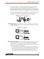
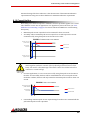
2.5.2 Incremental Encoder
Analog servo drives that use encoder feedback utilize two single-ended or differential
incremental encoder inputs for velocity control. The encoder provides incremental position
feedback that can be extrapolated into very precise velocity information. The encoder signals
are read as "pulses" that the drive uses to essentially keep track of the motor’s position and
direction of rotation. Based on the speed and order in which these pulses are received from
the two encoder signals, the drive can interpret the motor velocity.
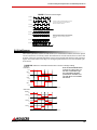
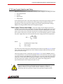
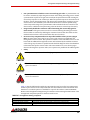
Figure 2.7 represents differential encoder "pulse" signals, showing how depending on which
signal is read first and at what frequency the "pulses" arrive, the speed and direction of the
motor shaft can be extrapolated. By keeping track of the number of encoder "pulses" with
respect to a known motor "home" position, servo drives are able to ascertain the actual motor
location.
MNALHWIN-05
11
Products and System Requirements / Feedback Specifications
FIGURE 2.7 Encoder Feedback Signals
Encoder A+
Encoder AExample 1: Encoder-A precedes Encoder-B. The pulses
arrive at a certain frequency, providing speed and
directional information to the drive.
Encoder B+
Encoder B-
Encoder A+
Encoder A-
Example 2: Encoder-B precedes Encoder-A, meaning the
direction is opposite from Example 1. The signal frequency
is also higher, meaning the speed is greater than in
Example 1.
Encoder B+
Encoder B-
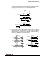
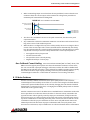
2.5.3 Hall Sensors
Three Phase (Brushless) drives use Hall Sensors for commutation feedback, and in the special
case of some drives, for velocity control. The Hall Sensors are built into the motor to detect the
position of the rotor magnetic field. These sensors are mounted such that they each generate a
square wave with either a 120-degree or 60-degree phase difference over one electrical cycle
of the motor.
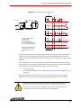
FIGURE 2.8 Hall Sensor Commutation and Motor Phase Current for 120-Degree Phasing
Hall Sensor
Commutation
Note: Not all ADVANCED Motion
Controls’ servo drive series use
the same commutation logic.
The commutation diagrams
provided here should be used
only with drives covered within
this manual.
High (1)
Hall A
Low (0)
High (1)
Hall B
Low (0)
High (1)
Hall C
Low (0)
0
60
120
180
240
300
360
Electrical Degrees
0
60
120
180
240
300
360
Electrical Degrees
Motor Phase
Current
High
Phase A
Low
High
Phase B
Low
High
Phase C
Low
MNALHWIN-05
12
Products and System Requirements / Feedback Specifications
Depending on the motor pole count, there may be more than one electrical cycle for every
motor revolution. For every actual mechanical motor revolution, the number of electrical cycles
will be the number of motor poles divided by two. For example:
a 6-pole motor contains 3 electrical cycles per motor revolution
a 4-pole motor contains 2 electrical cycles per motor revolution
a 2-pole motor contains 1 electrical cycle per motor revolution
•
•
•
The drive powers two of the three motor phases with DC current during each specific Hall
Sensor state:
The table below shows the valid commutation states for both 120-degree and 60-degree
phasing.
TABLE 2.8 Commutation Sequence Table
60 Degree
Valid
Invalid
120 Degree
Motor
Hall 1
Hall 2
Hall 3
Hall 1
Hall 2
Hall 3
Phase A
Phase B
Phase C
1
0
0
1
0
0
HIGH
-
LOW
1
1
0
1
1
0
-
HIGH
LOW
1
1
1
0
1
0
LOW
HIGH
-
0
1
1
0
1
1
LOW
-
HIGH
0
0
1
0
0
1
-
LOW
HIGH
0
0
0
1
0
1
HIGH
LOW
-
1
0
1
1
1
1
-
-
-
0
1
0
0
0
0
-
-
-
2.5.4 Tachometer
A DC Tachometer can be used on some drives for velocity control. The tachometer provides an
analog DC voltage feedback signal that is related to the actual motor speed and direction. The
drive subsequently adjusts the output current based on the error between the tachometer
feedback and the input command voltage. The maximum range of the tachometer feedback
signal is ±60 VDC.
Some applications may require an increase in the gain of the tachometer input signal. This
occurrence will be most common in designs where the tachometer input has a low voltage to
RPM scaling ratio. Some drive models offer a through-hole location listed on the specific drive
datasheet where a resistor can be added to increase the tachometer gain. Use the drive’s block
diagram to determine an appropriate resistor value.
See “Tachometer Input Gain Scaling” on page 45 for more information.
MNALHWIN-05
13
Products and System Requirements / Modes of Operation
2.6 Modes of Operation
The family of analog drives offers a variety of different control methods. While some drives in
the series are designed to operate solely in one mode, on other drives it is possible to select the
control method by DIP switch settings (see “Potentiometer Function Details” on page 43 for
more information). Consult the datasheet for the drive in use to see which modes are available
for use.
The name of the mode refers to which servo loop is being closed in the drive, not the endresult of the application. For instance, a drive operating in Current (Torque) Mode may be used
for a positioning application if the external controller is closing the position loop. Oftentimes,
mode selection will be dependent on the requirements and capabilities of the controller being
used with the drive as well as the end-result application.
2.6.1 Current (Torque) Mode
In Current (Torque) Mode, the input command voltage controls the output current. The drive
will adjust the output duty cycle to maintain the commanded output current. This mode is used
to control torque for rotary motors (force for linear motors), but the motor speed is not
controlled. The output current can be monitored through an analog current monitor output
pin. The voltage value read at the “Current Monitor Output” can be multiplied by a scaling
factor found on the drive datasheet to determine the actual output current.
Note
While in Current (Torque) Mode, the drive will maintain a commanded
torque output to the motor based on the input reference command.
Sudden changes in the motor load may cause the drive to be outputting
a high torque command with little load resistance, causing the motor to
spin rapidly. Therefore, Current (Torque) Mode is recommended for
applications using a digital position controller to maintain system stability.
2.6.2 Duty Cycle (Open Loop) Mode
In Duty Cycle Mode, the input command voltage controls the output PWM duty cycle of the
drive, indirectly controlling the output voltage. Note that any fluctuations of the DC supply
voltage will affect the voltage output to the motor.
This mode is recommended as a method of controlling the motor
velocity when precise velocity control is not critical to the application,
and when actual velocity feedback is unavailable.
Note
MNALHWIN-05
14
Products and System Requirements / Modes of Operation
2.6.3 Hall Velocity Mode
In Hall Velocity Mode, the input command voltage controls the motor velocity, with the Hall
Sensor frequency closing the velocity loop. An analog velocity monitor output allows
observation of the actual motor speed through a Hz/V scaling factor found on the drive
datasheet. The voltage value read at the velocity monitor output can be used to determine the
motor RPM through the scaling factor. See “Velocity Monitor Output” on page 42 for the motor
RPM equation.
Note
Due to the inherent low resolution of motor mounted Hall Sensors, Hall
Velocity Mode is not recommended for low-speed applications below
300 rpm for a 6-pole motor, 600 rpm for a 4-pole motor, or 900 rpm for a
2-pole motor. Hall Velocity Mode is better suited for velocity control
applications where the motor will be spinning at higher speeds.
2.6.4 Encoder Velocity Mode
In Encoder Velocity Mode, the input command controls the motor velocity, with the frequency
of the encoder pulses closing the velocity loop. An analog velocity monitor output allows
observation of the actual motor speed through a kHz/V scaling factor found on the drive
datasheet. The voltage value read at the velocity monitor output can be used to determine the
motor RPM through the scaling factor. See “Velocity Monitor Output” on page 42 for the motor
RPM equation.
Note
The high resolution of motor mounted encoders allows for excellent
velocity control and smooth motion at all speeds. Encoder Velocity
Mode should be used for applications requiring precise and accurate
velocity control, and is especially useful in applications where low-speed
smoothness is the objective.
2.6.5 Tachometer Velocity Mode
In Tachometer Velocity Mode, the input command voltage controls the motor velocity. This
mode uses an external DC tachometer to close the velocity loop. The drive translates the DC
voltage from the tachometer into motor speed and direction information.
DC Tachometers have infinite resolution, allowing for extremely accurate
velocity control. However, they also may be susceptible to electrical
noise, most notably at low speeds.
Note
MNALHWIN-05
15
Products and System Requirements / Modes of Operation
2.6.6 Voltage Mode
In Voltage Mode the input reference signal commands a proportional motor voltage regardless
of power supply voltage variations. This mode is recommended for velocity control when
velocity feedback is unavailable and load variances are small.
2.6.7 IR Compensation Mode
If there is a load torque variation while in Voltage Mode, the motor current will also vary as
torque is proportional to motor current. Hence, the motor terminal voltage will be reduced by
the voltage drop over the motor winding resistance (IR), resulting in a speed reduction. Thus,
motor speed, which is proportional to motor voltage (terminal voltage minus IR drop) varies
with the load torque.
In order to compensate for the internal motor voltage drop, a voltage proportional to motor
current can be added to the output voltage. An internal resistor adjusts the amount of
compensation, and an additional through-hole resistor can be added to the location listed on
the drive datasheet. Use caution when adjusting the IR compensation level. If the feedback
voltage is high enough to cause a rise in motor voltage with increased motor current,
instability occurs. Such a result is due to the fact that increased voltage increases motor speed
and thus load current which, in turn, increases motor voltage. If a great deal of motor torque
change is anticipated, it may be wise to consider the addition of a speed sensor to the motor
(e.g. tachometer, encoder, etc.).
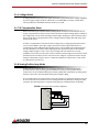
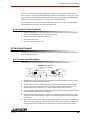
2.6.8 Analog Position Loop Mode
In this mode the feedback device is an analog potentiometer mechanically tied to the
positioned object, thus providing position feedback. The wiper of the potentiometer is
connected to one of the differential input terminals (-REF). The command is an analog signal,
which is connected to the other differential input terminal (+REF).
It is recommended to use a tachometer to close the velocity loop. The input reference gain can
be increased in the drive hardware for the Analog Position Loop Mode by ordering the -ANP
extension. The following figure is a typical wiring diagram of Analog Position Loop Mode.
FIGURE 2.9 Analog Position Loop Mode Configuration
Analog Servo
Drive
Motor
Outputs
Tach+
Tach-
Tach Motor
Load
Pot1
(>20k)
+10V
+Ref
Command
-Ref
-10V
GND
MNALHWIN-05
Return
16
Products and System Requirements / System Requirements
2.7 System Requirements
To successfully incorporate an analog servo drive into your system, you must be sure it will
operate properly based on electrical, mechanical, and environmental specifications, follow
some simple wiring guidelines, and perhaps make use of some accessories in anticipating
impacts on performance. Before selecting an analog servo drive, a user should consider the
requirements of their system. This involves calculating the required voltage, current, torque,
and power requirements of the system, as well as considering the operating environment and
any other equipment the drive will be interfacing with.
2.7.1 Analog Servo Drive Selection and Sizing
Analog servo drives have a given current and voltage rating unique to each drive. Based on the
necessary application requirements and the information from the datasheet of the motor
being used, a drive may be selected that will best suit the motor capabilities.
A drive should be selected that will meet the peak and continuous current requirements of the
application, and operate within the voltage requirements of the system.
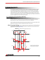
Motor Current and Voltage Motor voltage and current requirements are determined based
on the maximum required torque and velocity. These requirements can be derived from the
application move profiles (Figure 2.10).
FIGURE 2.10 Example Velocity, Torque, and Power Curves
1 Cycle
Velocity
Dwell
Dwell
Time
Torque
RMS
Time
Power
Power is equal to Torque x Velocity. Motor
Voltage (Vm) and Motor Current (Im) should
be chosen where power is at a maximum.
Time
MNALHWIN-05
17
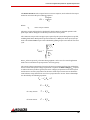
Products and System Requirements / System Requirements
The motor current IM is the required motor current in amps DC, and is related to the torque
needed to move the load by the following equation:
Torque
I M = ------------------KT
Where:
KT
-motor torque constant
The motor current will need to be calculated for both continuous and peak operation. The
peak torque will be during the acceleration portion of the move profile.
The continuous torque is the average torque required by the system during the move profile,
including dwell times. Both peak torque and continuous, or RMS (root mean square) torque
need to be calculated. RMS torque can be calculated by plotting torque versus time for one move
cycle.
T RMS =
2
Ti ti
i
---------------ti
i
Here Ti is the torque and ti is the time during segment i. In the case of a vertical application
make sure to include the torque required to overcome gravity.
The system voltage requirement is based on the motor properties and how fast and hard the
motor is driven. The system voltage requirement is equal to the motor voltage, VM, required
to achieve the move profile. In general, the motor voltage is proportional to the motor speed
and the motor current is proportional to the motor shaft torque. Linear motors exhibit the
same behavior except that in their case force is proportional to current. These relationships
are described by the following equations:
Vm = Im Rm + E
E = Ke Sm
MNALHWIN-05
for rotary motors
T = Kt Im
for linear motors
F = Kf Im
18
Products and System Requirements / System Requirements
Where:
Vm
Im
Rm
E
T
F
Kt
Kf
Ke
Sm
-motor voltage
-motor current (use the maximum current expected for the application)
-motor line-to-line resistance
-motor back-EMF voltage
-motor torque
-motor force
-motor torque constant
-motor force constant
-voltage constant
-motor speed (use the maximum speed expected for the application)
The motor manufacturer’s data sheet contain Kt (or Kf) and Ke constants. Pay special attention
to the units used (metric vs. English) and the amplitude specifications (peak-to-peak vs. RMS,
phase-to-phase vs. phase-to-neutral).
The maximum motor terminal voltage and current can be calculated from the above equations.
For example, a motor with a Ke = 10V/Krpm and required speed of 3000 RPM would require
30V to operate. In this calculation the IR term (voltage drop across motor winding resistance)
is disregarded. Maximum current is maximum torque divided by Kt. For example, a motor with
Kt = 0.5 Nm/A and maximum torque of 5 Nm would require 10 amps of current. Continuous
current is RMS torque divided by Kt.
Motor Inductance The motor inductance is vital to the operation of analog servo drives, as it
ensures that the DC motor current is properly filtered.
A motor that does not meet the rated minimum inductance value of the
drive may damage the drive! If the motor inductance value is less than
the minimum required for the selected drive, use of an external filter card
is necessary. See “Inductive Filter Cards” on page 29 for more
information.
A minimum motor inductance rating for each specific drive can be found in the datasheet. If
the drive is operated below the maximum rated voltage, the minimum load inductance
requirement may be reduced.
In the above equations the motor inductance is neglected. In brushless systems the voltage
drop caused by the motor inductance can be significant. This is the case in high-speed
applications if motors with high inductance and high pole count are used. Please use the
following equation to determine motor terminal voltage (must be interpreted as a vector).
V m = ( R m + jωL )I m + E
Where:
L
ω
MNALHWIN-05
-phase-to-phase motor inductance
-maximum motor current frequency
19
Products and System Requirements / System Requirements
2.7.2 Power Supply Selection and Sizing
There are several factors to consider when selecting a power supply for an analog servo drive.
•
•
•
•
Power Requirements
Isolation
Regeneration
Voltage Ripple
Power Requirements refers to how much voltage and current will be required by the drive in
the system. Isolation refers to whether the power supply needs an isolation transformer.
Regeneration is the energy the power supply needs to absorb during deceleration. Voltage
Ripple is the voltage fluctuation inherent in unregulated supplies.
Power Supply Current and Voltage The power supply current rating is based on the
maximum current that will be required by the system. If the power supply powers more than
one drive, then the current requirements for each drive should be added together. Due to the
nature of servo drives, the current into the drive does not always equal the current out of the
drive. However, the power in is equal to the power out. Use the following equation to calculate
the power supply output current, IPS, based on the motor voltage and current requirements.
VM ⋅ IM
----------------------------I PS =
V PS ⋅ ( 0.98 )
Where:
VPS
IM
VM
-nominal power supply voltage
-motor current
-motor voltage
Use values of Vm and Im at the point of maximum power in the move profile, Figure 2.10 (when
VMIM = max). This will usually be at the end of a hard acceleration when both the torque and
speed of the motor is high.
The power supply current is a pulsed DC current (Figure 2.11): when the MOSFET switch is
on, it equals the motor current; when the MOSFET is off it is zero. Therefore, the power supply
current is a function of the PWM duty cycle and the motor current (e.g. 30% duty cycle and 12
amps motor current will result in 4 amps power supply current). 30% duty cycle also means
that the average motor voltage is 30% of the DC bus voltage. Power supply power is
approximately equal to drive output power plus 3 to 5%.
The only time the power supply current needs to be as high as the drive
output current is if the move profile requires maximum current at
maximum velocity. In many cases however, maximum current is only
required at start up and lower currents are required at higher speeds.
MNALHWIN-05
20
Products and System Requirements / System Requirements
FIGURE 2.11 Unregulated DC Power Supply Current
PWM
Switching
Time
MOSFET ON
Vm
MOSFET OFF
Im
Ip
DIODE BRIDGE
Average
Time
Vm
Vp
Ripple Current
Im
Id
Motor
AC Input
Voltage
Time
SERVO DRIVE
Id
Vp = VAC*1.41
Average
Time
Ip
Vm = Motor Terminal Voltage
Im = Motor Current
Id = Diode Current
Ip = Power Supply Current
Vp = DC Power Supply Voltage
VAC = AC Supply Voltage (RMS)
The ripple current depends on the
motor inductance and the duty
cycle (MOSFET ON vs. OFF
time)
Average
Time
Vp
Time
50usec
A system will need a certain amount of voltage and current to operate properly. If the power
supply has too little voltage/current the system will not perform adequately. If the power
supply has too much voltage the drive may shut down due to over voltage, or the drive may be
damaged.
To avoid nuisance over- or under-voltage errors caused by fluctuations in the power supply,
the ideal system power supply voltage should be at least 10% above the entire system voltage
requirement, and at least 10% below the lowest value of the following:
—
—
Drive over voltage
External shunt regulator turn-on voltage (see “Regeneration and Shunt Regulators” on
page 23)
These percentages also account for the variances in Kt and Ke, and losses in the system
external to the drive. The selected margin depends on the system parameter variations.
Do not select a supply voltage that could cause a mechanical overspeed in the event of a drive malfunction or a runaway condition.
Brushed Motors may have voltage limitations due to the mechanical
commutators. Consult the manufacturer’s data sheets.
MNALHWIN-05
21
Products and System Requirements / System Requirements
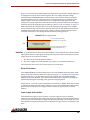
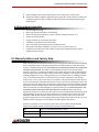
Figure 2.12 provides one possible example of an appropriate system power supply voltage for
an analog drive using an external shunt regulator. The over voltage and under voltage
shutdown levels on ADVANCED Motion Controls drives can be found on the drive datasheet.
The shunt regulator turn-on voltage was chosen at an appropriate level to clamp the power
supply voltage so it will not exceed the drive over voltage limit during regeneration. The
system power supply requirement is based on the motor properties and how much voltage is
needed to achieve the application move profile (see “Motor Current and Voltage” on page 17).
Keep in mind that the calculated value for Vm is the minimum voltage required to complete
moves at the desired speed and torque. There should be at least 10% headroom between the
calculated value and the actual power supply voltage to allow for machine changes such as
increased friction due to wear, change in load, increased operating speed, etc.
FIGURE 2.12 Power Supply Selection
100
Drive Over Voltage Shutdown (88V)
Shunt Regulator Turn-On Voltage (80V)
80
VDC
60
40
Acceptable Power Supply
Range (26 V-72V)
20
0
System Power Supply Requirement (24V)
Drive Under Voltage Shutdown (9V)
Isolation In systems where an AC line is involved, isolation is required between the AC line and the
signal pins on the drive. This applies to all systems except those that use a battery as a power
supply. There are two options for isolation:
1.
2.
The drive can have built in electrical isolation.
The power supply can provide isolation (e.g. a battery or an isolation transformer).
The system must have at least one of these options to operate safely.
Drive with Isolation
Some ADVANCED Motion Controls analog drives come with standard electrical isolation, while
others can be ordered with isolation as an option (see Figure 2.1, “Analog Product Family Part
Numbering Structure,”). To determine if a drive has isolation refer to the functional block
diagram on the drive datasheet. The isolation will be indicated by a dashed line through the
functional block diagram separating power ground from signal ground.
Drives with an "I" after the current rating in the part number (i.e. 30A8I), drives that are rated
to 400 VDC and drives that take AC line voltage for power come standard with isolation. Other
drives that do not fall into these categories can be ordered by special request to include
isolation.
Power Supply with Isolation
An isolated power supply is either a battery or a power supply that uses an isolation
transformer to isolate the AC line voltage from the power supply ground. This allows both the
power ground on an isolated power supply and the signal ground on a non-isolated drive to be
safely pulled to earth ground. Always use an isolated power supply if there is no isolation in the
drive.
MNALHWIN-05
22
Products and System Requirements / System Requirements
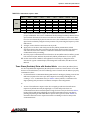
Regeneration and Shunt Regulators Use of a shunt regulator is necessary in systems
where motor deceleration or a downward motion of the motor load will cause the system’s
mechanical energy to be regenerated via the drive back onto the power supply.
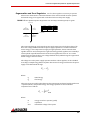
FIGURE 2.13 Four Quadrant Operation - Regeneration occurs when Torque and Velocity polarity are opposite
Current/Torque
IV
Regenerating
Counterclockwise
I
Motoring
Clockwise
I
Torque +
Velocity +
II
Torque -
Velocity +
Regen
III
Torque -
Velocity -
No Regen
IV
Torque +
Velocity -
Regen
No Regen
Voltage/Velocity
III
Motoring
Counterclockwise
II
Regenerating
Clockwise
This regenerated energy can charge the power supply capacitors to levels above that of the
drive over-voltage shutdown level. If the power supply capacitance is unable to handle this
excess energy, or if it is impractical to supply enough capacitance, then an external shunt
regulator must be used to dissipate the regenerated energy. Shunt regulators are essentially a
resistor placed in parallel with the DC bus. The shunt regulator will "turn-on" at a certain
voltage level (set below the drive over-voltage shutdown level) and discharge the regenerated
electric energy in the form of heat.
The voltage rise on the power supply capacitors without a shunt regulator, can be calculated
according to a simple energy balance equation. The amount of energy transferred to the power
supply can be determined through:
Ei = Ef
Where:
Ei
Ef
-initial energy
-final energy
These energy terms can be broken down into the approximate mechanical and electrical terms
- capacitive, kinetic, and potential energy. The energy equations for these individual
components are as follows:
1 2
E c = --- CV nom
2
Where:
Ec
C
Vnom
MNALHWIN-05
-energy stored in a capacitor (joules)
-capacitance
-nominal bus voltage of the system
23
Products and System Requirements / System Requirements
1 2
E r = --- Jω
2
Where:
-kinetic (mechanical) energy of the load (joules)
-inertia of the load (kg-m2)
-angular velocity of the load (rads/s)
Er
J
ω
E p = mgh
Where:
-potential mechanical energy (joules)
-mass of the load (kg)
-gravitational acceleration (9.81 m/s2)
-vertical height of the load (meters)
Ep
m
g
h
During regeneration the kinetic and potential energy will be stored in the power supply’s
capacitor. To determine the final power supply voltage following a regenerative event, the
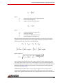
following equation may be used for most requirements:
( Ec ⋅ Er ⋅ Ep ) = ( Ec ⋅ Er ⋅ Ep )
i
f
1 2 1 2
1 2
1 2
--- CV nom + --- Jω i + mgh i = --- CV f + --- Jω f + mgh f
2
2
2
2
Which simplifies to:
Vf =
2mg ( h i – h f )
2
2
J 2
--V nom + ( ω i – ω f ) + ------------------------------C
C
The Vf calculated must be below the power supply capacitance voltage rating and the drive
over voltage limit. If this is not the case, a shunt regulator is necessary. A shunt regulator is
sized in the same way as a motor or drive, i.e. continuous and RMS power dissipation must be
determined. The power dissipation requirements can be determined from the application
move profile (see Figure 2.10).
ADVANCED Motion Controls offers a variety of shunt regulators for servo drives. When
choosing a shunt regulator, select one with a shunt voltage that is greater than the DC bus
voltage of the application but less than the over voltage shutdown of the drive. Verify the need
MNALHWIN-05
24
Products and System Requirements / System Requirements
for a shunt regulator by operating the servo drive under the worst-case braking and
deceleration conditions. If the drive shuts off due to over-voltage, a shunt regulator is
necessary.
Continuous Regeneration
In the special case where an application requires continuous regeneration (more than a few
seconds) then a shunt regulator may not be sufficient to dissipate the regenerative energy.
Please contact ADVANCED Motion Controls for possible solutions to solve this kind of
application. Some examples:
•
•
•
•
Web tensioning device
Electric vehicle rolling down a long hill
Spinning mass with a very large inertia (grinding wheel, flywheel, centrifuge)
Heavy lift gantry
Voltage Ripple For the most part, ADVANCED Motion Controls analog servo drives are
unaffected by voltage ripple from the power supply. The current loop is fast enough to
compensate for 60 Hz fluctuations in the bus voltage, and the components in the drive are
robust enough to withstand all but the most extreme cases. Peak to peak voltage ripple as high
as 25 V is acceptable.
There are some applications where the voltage ripple can cause unacceptable performance.
This can become apparent where constant torque or force is critical or when the bus voltage is
pulled low during high speed and high current applications. If necessary, the voltage ripple
from the power supply can be reduced, either by switching from single phase AC to three
phase AC, or by increasing the capacitance of the power supply.
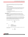
The voltage ripple for a system can be estimated using the equation:
I PS
V R = ---------- F f
C PS
Where:
VR
CPS
IPS
Ff
-voltage ripple
-power supply capacitance
-power supply output current
-frequency factor (1/hertz)
The power supply capacitance can be estimated by rearranging the above equation to solve for
the capacitance as:
I PS
C PS = -------- F f
VR
MNALHWIN-05
25
Products and System Requirements / System Requirements
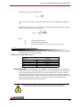
The frequency factor can determined from:
0.42
F f = ---------f
where f is the AC line frequency in hertz. Note that for half wave rectified power supplies, f =
f/2.
The power supply output current, if unknown, can be estimated by using information from the
output side of the servo drive as given below:
VM ⋅ I
M
---------------------------I PS =
V PS ⋅ ( 0.98 )
Where:
IM
VPS
VM
-current through the motor
-nominal power supply voltage
-motor voltage (see “Motor Current and Voltage” on page 17)
2.7.3 Environmental Specifications
To ensure proper operation of an analog servo drive, it is important to evaluate the operating
environment prior to installing the drive.
TABLE 2.9 Environmental Specifications
Environmental Specifications
Parameter
Description
Baseplate Temperature Range
See Drive Datasheet
Humidity
90%, non-condensing
Mechanical Shock
10g, 11ms, Half-sine
Vibration
2 - 2000 Hz @ 2.5g
Altitude
0-3000m
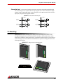
Shock/Vibrations While analog drives are designed to withstand a high degree of mechanical
shock and vibration, too much physical abuse can cause erratic behavior, or cause the drive to
cease operation entirely. Be sure the drive is securely mounted in the system to reduce the
shock and vibration the drive will be exposed to. The best way to secure the drive against
mechanical vibration is to use screws to mount the drive against its baseplate. For information
on mounting options and procedures, see “Mounting” on page 39 and the dimensional
drawings and information on the drive datasheet.
Care should be taken to ensure the drive is securely mounted in a
location where no moving parts will come in contact with the drive.
MNALHWIN-05
26
3
Integration in the Servo System
This chapter will give various details on incorporating an analog servo drive into a system, such as how to
properly ground the drive along with the entire system, and how to properly connect motor wires, power
supply wires, feedback wires, and inputs into the analog servo drive.
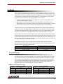
3.1 LVD Requirements
The servo drives covered in the LVD Reference report were investigated as components
intended to be installed in complete systems that meet the requirements of the Machinery
Directive. In order for these units to be acceptable in the end users’ equipment, the following
conditions of acceptability must be met.
1. European approved overload and current protection must be provided for the motors as
specified in section 7.2 and 7.3 of EN60204.1.
2. A disconnect switch shall be installed in the final system as specified in section 5.3 of
EN60204.1.
3. All drives that do not have a grounding terminal must be installed in, and conductively
connected to a grounded end use enclosure in order to comply with the accessibility
requirements of section 6, and to establish grounding continuity for the system in
accordance with section 8 of EN60204.1.
4. A disconnecting device that will prevent the unexpected start-up of a machine shall be
provided if the machine could cause injury to persons. This device shall prevent the
automatic restarting of the machine after any failure condition shuts the machine down.
5. European approved over current protective devices must be installed in line before the
servo drive, these devices shall be installed and rated in accordance with the installation
instructions (the installation instructions shall specify an over current rating value as low
as possible, but taking into consideration inrush currents, etc.). Servo drives that
incorporate their own primary fuses do not need to incorporate over protection in the
end users’ equipment.
These items should be included in your declaration of incorporation as well as the name and
address of your company, description of the equipment, a statement that the servo drives must
not be put into service until the machinery into which they are incorporated has been
declared in conformity with the provisions of the Machinery Directive, and identification of the
person signing.
MNALHWIN-05
27
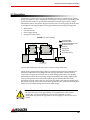
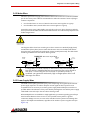
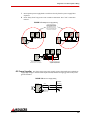
Integration in the Servo System / CE-EMC Wiring Requirements
3.2 CE-EMC Wiring Requirements
The following sections contain installation instructions necessary for meeting EMC
requirements.
General
1. Shielded cables must be used for all interconnect cables to the drive and the shield of the
cable must be grounded at the closest ground point with the least amount of resistance.
2. The drive’s metal enclosure must be grounded to the closest ground point with the least
amount of resistance.
3. The drive must be mounted in such a manner that the connectors and exposed printed
circuit board are not accessible to be touched by personnel when the product is in
operation. If this is unavoidable there must be clear instructions that the drive is not to be
touched during operation. This is to avoid possible malfunction due to electrostatic
discharge from personnel.
Analog Input Drives
4. A Fair Rite model 0443167251 round suppression core must be fitted to the low level
signal interconnect cables to prevent pickup from external RF fields.
PWM Input Drives
5. A Fair Rite model 0443167251 round suppression core must be fitted to the PWM input
cable to reduce electromagnetic emissions.
MOSFET Switching Drives
6. A Fair Rite model 0443167251 round suppression core must be fitted at the load cable
connector to reduce electromagnetic emissions.
7. An appropriately rated Cosel TAC series AC power filter in combination with a Fair Rite
model 5977002701 torroid (placed on the supply end of the filter) must be fitted to the
AC supply to any MOSFET drive system in order to reduce conducted emissions fed back
into the supply network.
IGBT Switching Drives
8. An appropriately rated Cosel TAC series AC power filter in combination with a Fair Rite
model 0443167251 round suppression core (placed on the supply end of the filter) must
be fitted to the AC supply to any IGBT drive system in order to reduce conducted
emissions fed back into the supply network.
9. A Fair Rite model 0443164151 round suppression core and model 5977003801 torroid
must be fitted at the load cable connector to reduce electromagnetic emissions.
Fitting of AC Power Filters
It is possible for noise generated by the machine to "leak" onto the main AC power, and then
get distributed to nearby equipment. If this equipment is sensitive, it may be adversely
affected by the noise. AC power filters can filter this noise and keep it from getting on the AC
power signal.The above mentioned AC power filters should be mounted flat against the
MNALHWIN-05
28
Integration in the Servo System / CE-EMC Wiring Requirements
enclosure of the product using the two mounting lugs provided on the filter. Paint should be
removed from the enclosure where the filter is fitted to ensure good metal to metal contact.
The filter should be mounted as close to the point where the AC power filter enters the
enclosure as possible. Also, the AC power cable on the load end of the filter should be routed as
far from the AC power cable on the supply end of the filter and all other cables and circuitry to
minimize RF coupling.
3.2.1 Ferrite Suppression Core Set-up
If PWM switching noise couples onto the feedback signals or onto the signal ground, then a
ferrite suppression core can be used to attenuate the noise. Take the motor leads and wrap
them around the suppression core as many times as reasonable possible, usually 2-5 times.
Make sure to strip back the cable shield and only wrap the motor wires. There will be two
wires for single phased (brushed) motors and 3 wires for three phase (brushless) motors.
Wrap the motor wires together as a group around the suppression core and leave the motor
case ground wire out of the loop. The suppression core should be located as near to the drive
as possible. TDK ZCAT series snap-on filters are recommended for reducing radiated
emissions on all I/O cables.
3.2.2 Inductive Filter Cards
Inductive filter cards are added in series with the motor and are used to increase the load
inductance in order to meet the minimum load inductance requirement of the drive. They also
serve to counteract the effects of line capacitance found in long cable runs and in high voltage
systems. These filter cards also have the added benefit of reducing the amount of PWM noise
that couples onto the signal lines.
Visit www.a-m-c.com/products/filter_cards.html for information on purchasing ADVANCED
Motion Controls inductive filter cards.
MNALHWIN-05
29
Integration in the Servo System / Grounding
3.3 Grounding
In most servo systems all the case grounds should be connected to a single Protective Earth
(PE) ground point in a "star" configuration. Grounding the case grounds at a central PE ground
point reduces the chance for ground loops and helps to minimize high frequency voltage
differentials between components. All ground wires must be of a heavy gauge and be as short
as possible. The following should be securely grounded at the central PE grounding point:
•
•
•
•
Motor chassis
Controller chassis
Power supply chassis
Analog Servo Drive chassis
FIGURE 3.1 System Grounding
+VDC
Command
Signal
Command
Signal
Case Ground Wire
Shield Ground Wire
Shielded Feedback/Signal Cable
Shielded Power Cable
+VDC
Controller
PE Ground
Signal Ground
Power Ground
Analog Servo Drive
Chassis Earth Ground
Isolated DC
Power Supply
Motor
Single Point System
Ground (PE Ground)
Ground cable shield wires at the drive side to a chassis earth ground point.
The DC power ground and the input reference command signal ground are oftentimes at a
different potential than chassis/PE ground. The signal ground of the controller must be
connected to the signal ground of the drive to avoid picking up noise due to the "floating"
differential servo drive input. In systems using an isolated DC power supply, signal ground
and/or power ground can be referenced to chassis ground. First decide if this is both
appropriate and safe. If this is the case, they can be grounded at the central grounding point.
For systems using AC power referenced to chassis ground, the drive must have internal optical
isolation to avoid a short through the the drive’s diode bridge.
Grounding is important for safety. The grounding recommendations in
this manual may not be appropriate for all applications and system
machinery. It is the responsibility of the system designer to follow
applicable regulations and guidelines as they apply to the specific servo
system.
MNALHWIN-05
30
Integration in the Servo System / Wiring
3.4 Wiring
Servo system wiring typically involves wiring a controller (digital or analog), a servo drive, a
power supply, and a motor. Wiring these servo system components is fairly easy when a few
simple rules are observed. As with any high efficiency PWM servo drive, the possibility of noise
and interference coupling through the cabling and wires can be harmful to overall system
performance. Noise in the form of interfering signals can be coupled:
•
•
•
•
Capacitively (electrostatic coupling) onto signal wires in the circuit (the effect is more
serious for high impedance points).
Magnetically to closed loops in the signal circuit (independent of impedance levels).
Electromagnetically to signal wires acting as small antennas for electromagnetic radiation.
From one part of the circuit to other parts through voltage drops on ground lines.
The main source of noise is the high DV/DT (typically about 1V/nanosecond) of the drive’s
output power stage. This PWM output can couple back to the signal lines through the output
and input wires. The best methods to reduce this effect are to move signal and motor leads
apart, use an inductive filter card, add shielding, and use differential inputs at the drive.
Unfortunately, low-frequency magnetic fields are not significantly reduced by metal enclosures.
Typical sources are 50 or 60 Hz power transformers and low frequency current changes in the
motor leads. Avoid large loop areas in signal, power-supply, and motor wires. Twisted pairs of
wires are quite effective in reducing magnetic pick-up because the enclosed area is small, and
the signals induced in successive twist cancel.
ADVANCED Motion Controls recommends using the following hand crimp tools for the
appropriate I/O and Feedback cable and wire preparation. Consult the drive datasheet to see
which connectors are used on a specific drive.
Drive Connector
Hand Crimp Tool Manufacturer and Part Number
16-pin, 2.54 mm spaced friction lock header
Molex: P/N 0638118200
Standard Density D-sub headers
Tyco: P/N 58448-2
High Density D-sub headers
Tyco: P/N 90800-1
3.4.1 Wire Gauge
As the wire diameter decreases, the impedance increases. Higher impedance wire will
broadcast more noise than lower impedance wire. Therefore, when selecting the wire gauge
for the motor power wires, power supply wires, and ground wires, it is better to err on the
side of being too thick rather than too thin. This becomes more critical as the cable length
increases. The following table provides recommendations for selecting the appropriate wire
size for a specific current. These values should be used as reference only. Consult any
applicable national or local electrical codes for specific guidelines.
TABLE 3.1 Current and Wire Gauges
Current (A)
Minimum Wire Size (AWG)
mm2
Current (A)
Minimum Wire Size (AWG)
mm2
10
#20
0.518
60
#10
5.26
15
#18
0.823
80
#8
8.37
20
#16
1.31
120
#6
13.3
35
#14
2.08
150
#0
53.5
45
#12
3.31
200
#00
67.4
MNALHWIN-05
31
Integration in the Servo System / Wiring
3.4.2 Motor Wires
The motor power wires supply power from the drive to the motor. Use of a twisted, shielded
pair for the motor power cables is recommended to reduce the amount of noise coupling to
sensitive components.
•
•
For a brushed motor or voice coil, twist the two motor wires together as a group.
For a brushless motor, twist all three motor wires together as a group.
Ground the motor power cable shield at one end only to the servo drive chassis ground. The
motor power leads should be bundled and shielded in their own cable and kept separate from
feedback signal wires.
DO NOT use wire shield to carry motor current or power!
The diagrams below show how an analog servo drive connects to a Brushed (single-phase)
and Brushless (three-phase) motor. Notice that the motor wires are shielded, and that the
motor housing is grounded to the single point system ground (PE Ground). The cable shield
should be grounded at the drive side to chassis ground.
FIGURE 3.2 Motor Power Output Wiring
ANALOG
SERVO DRIVE
BRUSHED
MOTOR
Shield
Motor C
MOT +
Motor
ANALOG
SERVO DRIVE
BRUSHLESS
MOTOR
Shield
Motor
MOT Single Point
System Ground
(PE Ground)
Chassis Ground
Motor B
Motor A
Single Point
System Ground
(PE Ground)
Chassis Ground
If using relays or other means to disconnect the motor leads, be
sure the drive is disabled before reconnecting the motor leads to
the drive. Connecting the motor leads to the drive while it is
enabled can generate extremely high voltage spikes which will
damage the drive.
3.4.3 Power Supply Wires
The PWM current spikes generated by the power output-stage are supplied by the internal
power supply capacitors. In order to keep the current ripple on these capacitors to an
acceptable level it is necessary to use heavy power supply leads and keep them as short as
possible. Reduce the inductance of the power leads by twisting them. Ground the power supply
cable shield at one end only to the servo drive chassis ground.
When multiple drives are installed in a single application, precaution regarding ground loops
must be taken. Whenever there are two or more possible current paths to a ground
connection, damage can occur or noise can be introduced in the system. The following rules
apply to all multiple axis installations, regardless of the number of power supplies used (see
Figure 3.3):
MNALHWIN-05
32
Integration in the Servo System / Wiring
1. Run separate power supply leads to each drive directly from the power supply filter
capacitor.
2. Never "daisy-chain" any power or DC common connections. Use a "star"-connection
instead.
FIGURE 3.3 Multiple Power Supply Wiring
These wiring schemes are
commonly practiced but often
contribute to noise problems.
Each additional node in the
chain adds to the amount of
noise and unnecessarily loads
the connectors in each link.
Analog
Servo
Drive
Analog
Servo
Drive
Analog
Servo
Drive
Analog
Servo
Drive
DC
Power
Supply
Analog
Servo
Drive
Analog
Servo
Drive
DC
Power
Supply
Power Supply
Capacitance
Power Supply
Capacitance
Analog
Servo
Drive
Analog
Servo
Drive
Analog
Servo
Drive
DC
Power
Supply
Power Supply
Capacitance
For AC input amplifiers, AC power
should be distributed from a
central AC source, not a capacitor
Wire pairs should be routed
together and twisted all the
way back to the power source
DC Power Supplies For drives using a DC power supply, connect the transformer-isolated DC
supply high voltage to the DC Power Input terminal, and the DC supply ground to the power
ground terminal.
FIGURE 3.4 DC Power Supply Wiring
ANALOG
SERVO DRIVE
Isolated DC
+HV
Power
GND
Supply
Shield
DC Power Input
Power Ground
Chassis Ground
Single Point
System Ground
(PE Ground)
MNALHWIN-05
33
Integration in the Servo System / Wiring
Single Phase AC Power Supplies Drives that accept only single-phase AC line power
include a standard 3-prong pluggable AC connector for attachment to an AC supply on the
underside of the drive (standard AC models), or on the front face of the drive (FAC models).
FIGURE 3.5 Pluggable AC Line Connectors
FAC drive model
features AC connector
on drive face
Standard AC connector
underneath drive
Three Phase AC Power Supplies Drives that accept three-phase AC line power have either
a 5-contact AC input screw terminal or a 4-port AC input connector. Connect a three phase AC
supply to AC1, AC2, and AC3, or L1, L2, and L3, depending on the drive model. On certain
models, a single phase AC supply can be connected to any two of the three AC terminals.
Consult the drive datasheet to determine if a specific drive model also accepts single phase AC.
FIGURE 3.6 Single or Three Phase AC Line Connections
ANALOG
SERVO DRIVE
Shield
3-Phase AC
Power
Supply*
Single Point
System Ground
(PE Ground)
AC1 or L1
FUSE
AC2 or L2
FUSE
AC3 or L3
FUSE
**
Chassis Ground
**Certain drive models include
internal AC line fuses. On
models that do not include
internal AC line fuses, external
fuses are recommended.
Consult the drive datasheet for
recommended values.
*For Single-phase AC Supply,
connect AC lines to any two of
AC1, AC2, and AC3. Do not
connect AC line neutral to
ground!
3.4.4 Feedback Wires
Use of a twisted, shielded pair for the feedback wires is recommended. Ground the shield at one
end only to the servo drive chassis ground. Route cables and/or wires to minimize their length
and exposure to noise sources. The motor power wires are a major source of noise, and the
motor feedback wires are susceptible to receiving noise. This is why it is never a good idea to
route the motor power wires with the motor feedback wires, even if they are shielded.
Although both of these cables originate at the drive and terminate at the motor, try to find
separate paths that maintain distance between the two. A rule of thumb for the minimum
distance between these wires is 10cm for every 10m of cable length.
FIGURE 3.7 Feedback Wiring
Motor Feedback
Analog
Servo
Drive
Avoid running
feedback and power
wires together
Motor
Motor Feedback
Analog
Servo
Drive
Separate power and
feedback wires
where possible
Motor
Motor Power
Motor Power
MNALHWIN-05
34
Integration in the Servo System / Wiring
Hall Sensors Brushless drives accept single-ended Hall Sensor feedback for commutation and
velocity control. Most drives also include a +6V, 30 mA low voltage supply output that can be
used to power the Hall Sensors. Verify on the motor datasheet that the voltage and current
rating of the supply output will work with the Hall Sensors before connecting.
FIGURE 3.8 Hall Sensor Input Connections
ANALOG
SERVO DRIVE
+V HALL (Power for Hall Sensors)
Shield
HALL A +
HALL B +
Motor
HALL C +
Signal Ground
Chassis Ground
Incremental Encoder Some drive models support either single-ended or differential
incremental encoder feedback. If using a single-ended encoder with a drive that accepts
differential inputs, leave the negative terminal open. Both the "A" and "B" channels of the
encoder are required for operation. Drives that accept differential signals also accept an
optional "index" channel that can be used for synchronization and homing. If using the +5V,
150mA (or 250mA) low voltage power supply output from the drive, verify that the supply
output voltage and current rating is sufficient for the encoder specifications.
FIGURE 3.9 Incremental Encoder Connections
ANALOG SERVO
DRIVE
+5V Encoder Supply Output
Signal Ground
+
MOTOR ENC A+
-
MOTOR ENC A-
+
MOTOR ENC I+
Enc I
MOTOR ENC I-
Enc A
Incremental
Encoder
Shield
Motor
+
MOTOR ENC B+
Enc B -
MOTOR ENC BChassis
Ground
MNALHWIN-05
35
Integration in the Servo System / Wiring
Tachometer For drives that accept a Tachometer for velocity control, connect the negative
tachometer input to the tachometer input on the drive, and connect the positive tachometer
input to signal ground. The drive must be in Tachometer Velocity mode in order to properly
use the tachometer input. See the drive datasheet for specific DIP switch settings. The
tachometer has a range of ±60 VDC. Certain drive models allow scaling of the allowable
tachometer voltage range. Consult the drive datasheet for tachometer scaling instructions.
FIGURE 3.10 Tachometer Input Connections
ANALOG
SERVO DRIVE
Tachometer
(± 60 VDC)
Tach-
TACHOMETER INPUT
Motor
SIGNAL GROUND
Tach+
Chassis
Ground
3.4.5 Input Reference Wires
Use of a twisted, shielded pair for the input reference wires is recommended. Connect the
reference source "+" to "+REF IN", and the reference source "-" (or common) to "-REF IN".
Connect the shield to the servo drive chassis ground. The servo drive’s reference input circuit
will attenuate the common mode voltage between signal source and drive power grounds.
In case of a single-ended reference signal, connect the command
signal to "+ REF IN" and connect the command return and "- REF IN" to
signal ground.
Long signal wires (10-15 feet and up) can also be a source of noise when driven from a typical
op-amp output. Due to the inductance and capacitance of the wire the op-amp can oscillate. It
is always recommended to set a fixed voltage at the controller and then check the signal at the
drive with an oscilloscope to make sure that the signal is noise free.
±10V Analog Input When using a ±10V analog signal for an input command, it is important to
consider the output impedance of the analog source when interfacing to input circuitry. A
poorly designed ±10V analog input interface can lead to undesired command signal
attenuation. Figure 3.11 shows an external analog source connected to an analog input. The
ideal voltage delivered to the input is VS. However, the voltage drop across Rsource will reduce
the signal being delivered to the drive input. This voltage drop is dependent on the value of
Rsource and the drive’s input impedance.
FIGURE 3.11 Analog Source and Drive Input
+/- 10V ANALOG
SOURCE
Rsource
Vs
+
-
ANALOG
SERVO DRIVE
+REF
-REF
+/- 10V ANALOG
SOURCE
Rsource
+
Internal Offset
Reference Voltage
MNALHWIN-05
Vs
+
-
ANALOG
SERVO DRIVE
+REF
-REF
Rin
Equivalent Input
Impedance
36
Integration in the Servo System / Wiring
The drive’s analog input can be simplified to a single impedance, Rin, as shown in Figure 3.11.
If the impedance of Rsource is of the same magnitude or larger than Rin, there will be a
significant voltage drop across Rsource. Reduced values of Rsource cause a lower voltage drop
that increases signal integrity. In order to avoid a voltage drop of more than 5% between the
source and the drive, it is recommended to use an Rsource value of less than or equal to 2kohm.
If there is a large output impedance from the analog source, it is recommended to use a buffer
circuit between the analog source output and the drive input. A unity gain op-amp circuit as
shown in Figure 3.12 will ensure low output impedance with minimal voltage drop.
FIGURE 3.12 Optimized Low Impedance Interface
ANALOG
SERVO DRIVE
+/- 10V ANALOG
SOURCE
-
Rsource
Vs
+
+
-
+REF
-REF
+
Internal Offset
Reference Voltage
Potentiometer Input Analog servo drives that accept ±10V analog input can be commanded
with the use of an external potentiometer and a DC supply by varying the DC supply voltage
across the potentiometer.
FIGURE 3.13 Potentiometer Input
Bi-directional Control
+/- VDC
Power
Supply
+10V
+10V Max
Potentiometer
(~50k)
-10V
GND
ANALOG
SERVO DRIVE
+REF IN
-REF IN
-10V Max
SIGNAL GROUND
Uni-directional Control
+VDC
Power
supply
+10V
+10V Max
Potentiometer
(~50k)
ANALOG
SERVO DRIVE
+REF IN
-REF IN
GND
SIGNAL GROUND
PWM and Direction Inputs On drives that accept a PWM and Direction signal for a command
input, the inputs are optically isolated from the power stage of the drive. The PWM and
Direction, Inhibit, and Fault I/O will not provide any functionality to the drive unless the
optocouplers are activated. Depending on the drive model, there are two methods to activate
the optocouplers and thereby activate the drive.
•
MNALHWIN-05
Some drive models feature a +5V input pin that is used to drive the optocoupler inputs.
This +5V supply must be grounded at the negative Inhibit terminal. The positive terminals
for the PWM, Direction, and Inhibit inputs are all internally connected to the +5V input.
Therefore, the external PWM and Direction input signals should be connected at the
negative PWM and Direction terminals. The positive Fault output terminal can also be
37
Integration in the Servo System / Wiring
connected to the +5V input supply, and when the drive enters a fault stage, the negative
Fault output terminal will rise to the +5V supply indicating a fault condition.
FIGURE 3.14 PWM and Direction Optocoupled Inputs, +5V supply input option
ANALOG
SERVO DRIVE
+5V
+5V
Input
100
PWM+
PWM Input Signal
500
PWM+5V
Input
100
DIR+
Direction Input Signal
+5V
DIR5k
+5V
FAULT+
Fault Monitor Output
100
FAULT+5V
Input
INHIBIT+
Ground to Inhibit / Open to Enable
+5V
100
INHIBIT5k
GND
+5V
Supply
•
+5V Input
+5V
On drives that do not contain an additional +5V input supply pin, there are two options to
activate the optocouplers. The positive terminals of the PWM, Direction, Fault, and Inhibit
I/O can be brought to an external +5V supply, or the negative terminals of the PWM,
Direction, Fault, and Inhibit I/O can be brought to ground.
FIGURE 3.15 PWM and Direction Optocoupled Inputs
ANALOG
SERVO DRIVE
ANALOG
SERVO DRIVE
+5V
PWM+
PWM Input Signal
100
PWM Input Signal
PWM-
GND
PWM+
100
PWM-
5k
+5V
DIR+
Direction Input Signal
100
5k
Direction Input Signal
DIR-
GND
DIR+
100
DIR-
5k
+5V
FAULT+
Fault Monitor Output
100
FAULT-
5k
Fault Monitor Output
GND
FAULT+
100
FAULT-
+5V
INHIBIT+
Ground to Inhibit / Open to Enable
MNALHWIN-05
INHIBIT-
100
+5V to Inhibit / Open to Enable
GND
INHIBIT+
100
INHIBIT-
38
Integration in the Servo System / Mounting
Sinusoidal Input The S-Series of analog servo drives accept two sinusoidal command signals
that are 120 degrees out of phase. The sine input signals can be either differential or singleended. If using a single-ended signal, connect the input to the +REF terminal of the reference
input pins, and ground the negative terminal.
FIGURE 3.16 Sinusoidal Command Inputs
Analog Servo
Drive
Differential
Sine Input A
+ REF-IN-A
40k
- REF-IN-A
Analog Servo
Drive
+
+ REF-IN-A
Single-ended
Sine Input A
40k
Differential
Sine Input B
+ REF-IN-B
40k
- REF-IN-B
40k
40k
+
- REF-IN-A
40k
+
+ REF-IN-B
Single-ended
Sine Input B
40k
+
- REF-IN-B
40k
3.5 Mounting
ADVANCED Motion Controls analog servo drives provide mounting hole locations on the
baseplate allowing the drive to be mounted either vertically or horizontally. Drives can be
mounted to a heatsink or other plane surface, or attached to a lab rail either on a test bench or
as part of a larger system. Consult the drive datasheet for specific mounting dimensions and
mounting hole locations.
FIGURE 3.17 Analog Servo Drives Mounting Options
ADVAN
MOTIO
CED
N CO NT
ROLS
ADVAN
C
MOTIO
N CONT
ED
RO LS
ED
ON
T RO
LS
AN C
NC
A DV
MO
TIO
MNALHWIN-05
39
4
Operation
This chapter will describe the operation and setup of an ADVANCED Motion Controls analog servo drive.
4.1 Initial Setup and Features
To begin operation with your analog servo drive, be sure to read and understand the previous
chapters in this manual as well as the drive datasheet. Be sure that all system specifications
and requirements have been met, and become familiar with the capabilities and functions of
the drive. Also, be aware of the “Troubleshooting” section at the end of this manual for
solutions to basic operation issues.
Do not install the servo drive into the system without first determining that all chassis power
has been removed for at least 10 seconds. Never remove a drive from an installation with
power applied. Carefully follow the grounding and wiring instructions in the previous
chapters to make sure your system is safely and properly set up.
4.1.1 Pin Function Details
The family of analog drives provide a number of various input and output pins for parameter
observation and drive configuration options. Not all drives will have each of the following pin
functions. Consult the drive datasheet to see which input/output pin functions are available for
each drive.
Current Monitor Output Measured relative to signal ground, power ground, or a separate
current monitor ground, depending on the drive model. Consult the drive datasheet to
determine the correct ground connection. The current monitor provides an analog voltage
output signal that is proportional to the actual drive current output. The scaling factor for each
individual drive can be found on the drive datasheet. The drive must be connected to a load in
order for the drive to output actual current.
Example Measurement
The current monitor pin on a drive with a current monitor scaling factor of 4 A/V is measured
to be 1.3V. This would mean the drive is outputting: (4 A/V)(1.3V) = 5.2A.
MNALHWIN-05
40
Operation / Initial Setup and Features
Current Reference Output Measured relative to signal ground, the current reference
provides an analog voltage output signal that is proportional to the command signal to the
internal current loop. The drive does not need to be connected to a load to read the current
reference output. The internal command current may differ from the actual drive output
current due to certain conditions such as a small load, drive faults, undersized power supplies,
inhibited drive, etc. The command to the internal current loop can be solved for by the
following equation:
I peak
I command = V current ref ⋅ ------------V
max
Where:
Icommand -command current to the internal current loop
Vcurrent ref -measured voltage at current reference pin
Ipeak
-peak current value of the drive
Vmax
-voltage corresponding to maximum internal current command, value
found on drive datasheet; on most drive models Vmax = 7.45V
Example Measurement
The current reference pin on a drive with a peak current value of 12A and Vmax of 7.45V is
measured to be 2.63V. Following the above equation to solve for Icommand, the command
current to the internal current loop would be 4.24A.
Inhibit Input This pin provides a +5V TTL input that allows a user to enable/disable the drive by
either connecting this pin to ground or by applying a +5VDC voltage level to this pin,
referenced to signal ground. By default, the drive will be enabled if this pin is high, and
disabled if this pin is low. This logic can be reversed, however, either through DIP switch
setting or by removing a SMT jumper from the PCB (consult the drive datasheet to see which
option is available; note that removal of the SMT jumper must be done by a person familiar
with SMT soldering, and that the drive warranty will be voided if the drive is damaged). This
will require all inhibit lines to be brought to ground to enable the drive. Most drives can also
be ordered with inverted inhibit logic as well (-INV option). Some drive models allow the drive
to be configured so the inhibit input does not trigger a drive fault state. Typically this is
achieved by DIP switch setting. Consult the drive datasheet to see if this option is available.
Directional Inhibits
Some drives also include directional inhibit pins that disable motor motion in either the
positive or negative direction, typically used for limit switches. These pins do not cause a drive
fault condition. They will follow the same logic (either standard or inverted) as the main
inhibit/enable input.
Continuous Current Limit Pin The Continuous Current Limit pin can be used to reduce the
factory-preset maximum continuous current limit without affecting the peak current limit of
the drive by attaching an external resistor between this pin and signal ground. Values for
resistors and the corresponding reduction in continuous current are given on the drive
datasheet. This continuous current reduction comes secondary to any reductions made by DIP
switch settings on the drive and the current limiting potentiometer.
MNALHWIN-05
41
Operation / Initial Setup and Features
Fault Output This pin provides a +5V TTL output measured relative to signal ground that will
indicate when the drive is subject to one of the following fault conditions: inhibit, invalid Hall
State, output short circuit, over voltage, over temperature, or power-up reset. On most drive
models this pin will read +5V (High) when the drive is in a fault state, but some drives allow
the logic to be reversed, so that a 0V (Low) fault output indicates a fault.
Analog drives automatically self-reset once all active fault conditions have been removed. For
instance if the DC power supply rises above the over-voltage shutdown level of the drive, the
Fault Output will indicate a fault, and the drive will be disabled. Once the DC power supply
level is returned to a value below the drive over-voltage shutdown level, the Fault Output will
return to the normal state, and the drive will automatically become enabled.
Low Voltage Power Supply Outputs Most drives include low voltage power supply
outputs meant for customer use. Consult the drive datasheet to see which low voltage outputs
are included on a specific drive.
•
•
±10V (or ±5V), 3mA Output - Typically used as an on-board ±10V analog input signal for
testing purposes. This output can be used in conjunction with an external potentiometer
to vary the input signal between ±10V.
+6V, 30mA Output - Available on three phase (brushless) drive only. This pin provides a
+6 VDC output that can be used to power Hall Sensors. Consult the motor datasheet to find
out which feedback wire from the motor is the Hall Sensor power supply wire.
Do not use this +6V supply to power an encoder. An encoder will require
a separate power supply. Consult the encoder datasheet or
specifications to determine the encoder voltage and current
requirements. Typical values are +5VDC at 150mA.
•
+5V, 150 mA (or 250mA) Output - Can be used as power for an encoder. Consult the
motor or encoder datasheet to determine the appropriate encoder voltage and current
requirements before connecting this supply.
Velocity Monitor Output This pin provides an analog voltage output that is proportional to
the actual motor speed. The scaling factor for each individual drive can be found on the drive
datasheet.
•
For a drive in Encoder Velocity Mode, substitute the voltage value read at the velocity
monitor pin, Vmonitor, into the below equation to determine the motor RPM:
V monitor ⋅ Scaling Factor ⋅ 60
Motor Velocity [RPM] = ---------------------------------------------------------------------Number of encoder lines
•
For a drive in Hall Velocity Mode, substitute the voltage value read at the velocity monitor
pin, Vmonitor, into the below equation to determine the motor RPM:
V monitor ⋅ Scaling Factor ⋅ 120
Motor Velocity [RPM] = ------------------------------------------------------------------------Number of motor poles
MNALHWIN-05
42
Operation / Initial Setup and Features
4.1.2 Potentiometer Function Details
All potentiometers vary in resistance from 0 to 50 kohm, over 12 turns. An additional full turn
that does not effect resistance is provided on either end, for a total of 14 turns. When the end of
potentiometer travel is reached, it will click once for each additional turn. Consult the drive
datasheet to see which potentiometers are included on a specific drive.
TABLE 4.1 Potentiometer Function Details
Potentiometer
Description
Loop Gain Adjustment
This potentiometer must be set completely counter-clockwise in Current Mode. In Velocity,
Voltage, or Duty Cycle Mode, this potentiometer adjusts the gain in the velocity forward position of
the closed loop. Turning this potentiometer clockwise increases the gain. Start from the full
counter-clockwise position, turn the potentiometer clockwise until the motor shaft oscillates, then
back off one turn.
Current Limit
This potentiometer adjusts the current limit of the drive. To adjust the current limit, first use any
available DIP switches or external current limiting resistors to set the maximum current limits and
ratios (consult drive datasheet to see which options are available). If further adjustment is
necessary, use the following equation to determine the number of clockwise turns from the full
counter-clockwise position necessary to set the desired current limit:
I system
# of turns (from full CCW) = ----------------- 12 + 1
I max
Isystem = the desired current limit of the system (typically determined by motor current rating)
Imax = maximum current capability of the drive; this value is determined after any external current
limiting resistors have been used and/or any current scaling or current reduction DIP switches
have been set. If no DIP switches or external resistors have been used, then Imax is the default
maximum continuous current limit set by the drive hardware. See “Current Limiting Procedure” on
page 46 for an example of how to use this potentiometer.
Reference Gain
This potentiometer adjusts the ratio between the input signal and the output variable (voltage,
current, velocity, or duty cycle). For a specific gain setting, turn this potentiometer fully counterclockwise, and adjust the command input to 1V. Then turn clockwise while monitoring motor
velocity or drive output voltage (depending on mode of operation) until the required output is
obtained for the given 1V command. Turning this potentiometer counter-clockwise decreases the
reference in gain, while setting this potentiometer in the fully clockwise position makes the whole
range of drive output available. This potentiometer may be left in the fully clockwise position if a
controller is used to close the velocity or position loops.
Test/Offset
This potentiometer acts as an internal command source for testing when the Test/Offset switch is
in the ON position. If the Test/Offset switch is in the OFF position, then this potentiometer can be
used to adjust a small amount of command offset in order to compensate for offsets that may be
present in the servo system. Turning this potentiometer clockwise adjusts the offset in a negative
direction relative to the +Ref input command.
Before offset adjustments are made, the reference inputs must be grounded or commanded to 0
volts.
Ramp Time
This potentiometer sets the ramp time for the command input signal. The ramp time can be set for
up to 30 seconds in reaching the max command by adjusting the potentiometer fully clockwise.
Ramping rates are linear with respect to time and apply to both directions of motion.
Test Points for Potentiometers After the potentiometer adjustments have been completed,
the resistance values can be measured for future adjustments or duplication on other servo
drives of the same part number. Test points for potentiometer wipers are provided and are
located at the foot of all four potentiometers. Resistance measurements are only to be used to
duplicate drive settings, since some potentiometers have other resistors in series or parallel.
Measure the resistance between the test point and the outer leg of the potentiometer or
between the test point and an appropriate ground. See the block diagram on the drive
datasheet to determine which ground should be used for each potentiometer.
Before taking potentiometer resistance measurements, make sure that
all potentiometers and DIP switches have been set to the desired
settings, and that all I/O and Feedback cables have been removed from
the drive, as these can affect resistance measurements.
MNALHWIN-05
43
Operation / Initial Setup and Features
4.1.3 Switch Function Details
Together with the described functions below certain switches may also be used in selecting the
mode of operation, while some may be used strictly for mode selection. Switch implementation
and functionality within the drive circuitry is included on the block diagram of the drive
datasheet. Consult the drive datasheet to see which switches are included on a specific drive.
TABLE 4.2 Switch Function Details
Switch
Description
Current Scaling
Changes the sensitivity of the current sense, thereby reducing the peak and continuous current
limits by a given amount.
Current Loop Proportional Gain
Adjustment
Adjusts the proportional gain of the current loop. For drive model S16A8, there are two Current
Loop Proportional Gain switches that must be set to the same setting.
Current Limit Ratio
Sets the continuous-to-peak current limit ratio to a given percentage. The default setting for all
drives is a continuous-to-peak current limit ratio of 50% (i.e., 12 amp peak limit, 6 amp continuous
limit).
Current Loop Integral Gain
Activates or deactivates the current loop integral gain. This switch is OFF by default. For drive
model S16A8, there are two Current Loop Integral Gain switches that must be set to the same
setting.
RMS Current Limit Setting
Sets the RMS current limit setting on sinusoidal input drives, used to reduce the continuous
current limit to a percentage of the maximum continuous limit. Two RMS Current Limit Setting
switches are used to set the percentage. See the drive datasheet for specific switch configuration.
Peak Current Limit
Sets the peak current to 50% or 100% of the maximum peak current limit on sinusoidal input
drives. Depending on the drive model, there are either two or three Peak Current Limit switches
that must all be set to the same setting.
Outer Loop Integration Activation
Activates or deactivates the outer loop integration. For Current Mode, outer loop integration should
be deactivated, but should be activated for other modes.
Outer Loop Integral Gain Adjustment
Increases or decreases the integral gain of the outer loop.
Duty Cycle Feedback
Enables/disables the duty cycle feedback. Duty cycle feedback is only enabled when the drive is
configured for Duty Cycle Mode.
Hall Sensor Commutation Phasing
Tells the drive the type of Hall sensor phasing the motor has. Switches between 120 and 60
degree phasing.
Test/Offset
Switches the drive between Test mode and Offset mode. In Test mode, the command signal is
adjustable via the Test/Offset potentiometer. In Offset mode, the drive will accept commands via
the reference inputs, but a small amount of offset can be adjusted in order to compensate for
offsets that may be present in the servo system.
PWM and Direction Test Signal
Activates or deactivates the PWM and Direction internal test signal, controlled by the PWM Test
Signal Adjustment potentiometer.
Velocity Feedback Polarity
Changes the polarity of the internal feedback signal and the velocity monitor output signal.
Inversion of the feedback polarity may be required to prevent a motor run-away condition. See
“Motor Problems” on page 61 for more information.
IR Compensation
Activates or deactivates IR feedback. IR feedback should be activated for IR Compensation Mode,
and deactivated for other modes.
Inhibit Logic
Sets the logic of the inhibit pins to Active High or Active Low.
Input Range Selection
Sets the voltage range of the sinusoidal command input pins. The input range can be set to ±5V or
±10V. Drives contain two Input Range Selection switches that must set to the same setting.
4.1.4 Adjustable Acceleration and Deceleration Rate
On some drive models, the acceleration and deceleration rates can be set independently using
through-hole resistors. The drive datasheet contains specific resistor values and the
corresponding ramping time. The rates are based on ±10 volts to the reference inputs. The
"time" listed in the table on the drive datasheet is the time it takes to reach the 10 volt input.
The ramping rates are linear with respect to time. For example, if the input were only 5 volts,
the time to ramp to this voltage would be half the time to ramp to 10 volts. These locations are
silk-screened on the PCB for easy identification. Two SMT jumpers (0 ohm resistors) are
required to be set appropriately in order to enable adjustable acceleration/deceleration rate
control. The default setting for both jumpers is to disable adjustable rate control. The specific
configuration of the jumpers for a drive are given on the drive datasheet.
MNALHWIN-05
44
Operation / Initial Setup and Features
4.1.5 Tachometer Input Gain Scaling
Standard drive tachometer inputs are typically pre-configured such that the standard 60k input
resistance scales the maximum tach input voltage to 60V. The 60k tachometer input resistance
is actually populated with a 50k resistor in series with a 10k resistor. Most drives with a
tachometer feedback input will also have either a through-hole resistor location in parallel
with the 50k resistor or tachometer scaling DIP Switch options.
FIGURE 4.1 Tachometer Input Resistance
ANALOG
SERVO DRIVE
Optional
Through-Hole
Tach Gain
Resistor
Tachometer Input
50k
10k
This allows users to reduce the effective input resistance to a value that more closely matches
their maximum application feedback voltage in order to increase the tachometer input gain.
An appropriate tachometer input resistance value should be at least 1000 times the maximum
tachometer voltage feedback value. From zero to infinite resistance (open connection), this
through-hole location can scale the tachometer’s maximum input voltage range from 10V to
60V.
To determine the maximum feedback voltage for the application:
1. Determine the absolute maximum speed required of the motor for the application (Sm, in
kRPM).
2. Look up the tachometer’s voltage to speed constant (Kv, in V/kRPM).
3. Calculate for the tachometer’s maximum voltage output in the application:
V max = K v ⋅ S m
Example
An application’s maximum motor speed is 4.7 kRPM, and the tachometer is rated for 7
V/kRPM. Using the above equation, the maximum voltage from the tachometer input, Vmax,
will be 33V. Therefore, the equivalent tachometer input resistance must be at least 33k.
Choosing an equivalent resistance value of 35k, solve for the required resistance of the
through-hole resistor.
( 50 ⋅ V max ) – 500
( 50 ⋅ 35 ) – 500
Tach Gain Through-Hole Resistor (in kohm) = ----------------------------------------- = ------------------------------------ = 50k
60 – 35
60 – V max
As solved for above, the equivalent 35k resistance can be acheived by adding a 50k throughhole resistor in parallel with the existing 50k resistor on the drive tachometer input.
Scaling the tachometer input gain is not a required procedure for all
applications. Most applications will work well even with low gains. The
effect of low gains is only a slower velocity loop response.
MNALHWIN-05
45
Operation / Initial Setup and Features
4.1.6 Current Limiting Procedure
Before operating a drive, the current output of the drive must be limited based on motor and
system current limitations. Depending on the drive model, ADVANCED Motion Controls’ analog
servo drives feature a number of different current limiting methods. However, the procedure
for setting the current limit will essentially be the same for each drive. Consult the drive
datasheet to see what current limiting options are available on a specific drive.
The current limiting steps should be taken with no power applied to the drive.
1. The following two options may be used separately or in conjunction with each other to
reduce the current limits. Keep in mind that any current reductions enacted by the use of
an external resistor will come secondary to DIP switch settings.
— If available, position any current scaling or current limit ratio DIP switches to the
desired position (see “Potentiometer Function Details” on page 43).
— If available, use an external resistor connected to the Continuous Current Limiting Pin
based on the values given on the drive datasheet (see “Continuous Current Limit Pin”
on page 41).
2. If further current limiting is necessary, use the Current Limit potentiometer to "fine tune"
the current limit to a final value (see “Potentiometer Function Details” on page 43).
Example
A 30A8 drive is going to be used with an application having a continuous current requirement
of 1.5 amps and a continuous current limit of 2.5 amps, and a peak current requirement of 6
amps, and a peak current limit of 10 amps. The 30A8 has a Current Scaling and Current Limit
Ratio switch, a Current Limit potentiometer, and the option of using an external resistor to
reduce the continuous current limit. This example will only use the DIP switches and
potentiometer.
1. Typically it is recommended to set the current limits of the drive below the continuous
and peak current limits of the motor or application, allowing some headroom for safety. In
this case, the drive continuous current limit will be chosen at 2 amps, and the peak
current limit at 9 amps.
2. Setting the Current Scaling switch to OFF will scale the peak and continuous current limits
by half, yielding a peak limit of 15 amps, and a continuous limit of 7.5 amps.
3. Setting the Current Limit Ratio switch to ON will change the continuous-to-peak current
ratio to 25%, yielding a peak limit of 15 amps, and a continuous limit of 3.75 amps.
4. To further reduce the current limits to the desired values, the Current Limit potentiometer
can be used. Begin with the continuous current requirement, using the equation to
determine the number of clockwise turns for the Current Limit potentiometer:
2amps
# of turns = ------------------------ 12 + 1
3.75amps
Solving for the number of turns yields approximately 7.5 turns in the clockwise direction
from the fully counter-clockwise position.
5. Since the continuous-to-peak ratio was set at 25% in Step 3, the number of turns
calculated above will yield a peak current limit of approximately 8 amps, thereby
satisfying both the continuous and peak current requirements of the application.
MNALHWIN-05
46
Operation / Initial Setup and Features
4.1.7 Drive Set-up Instructions
Single Phase (Brush Type)
1. It is recommended to reduce the drive output current to avoid motor over heating during
the setup procedure. Make sure the current has been set appropriately within the system
and motor limits based on the procedure outlined in “Current Limiting Procedure” on
page 46.
2. Check the power and connect it to the drive. Do not connect the motor lead wires.
3. Make sure the drive is in an enabled state via all inhibit/enable inputs. See drive datasheet
for details.
4. Check that the status LED indicates normal operation (GREEN).
5. Set mode according to the drive datasheet for Voltage Mode.
6. Set the Test/Offset switch to Test mode. Measure the voltage across the motor output with
a DC voltmeter. Slowly turn the Test/Offset potentiometer; the voltage should vary
between ± bus voltage. Set the output voltage with the Test/Offset potentiometer to a low
value.
7. Verify that the load circuit meets the minimum inductance requirements and that the
power supply voltage does not exceed the drive rated voltage or 150% of the nominal
motor voltage.
8. Turn the power off. Connect the motor. Turn the power back on. Gradually turn the
Test/Offset potentiometer to change motor speed in both directions. Set the Test/Offset
switch to Offset.
9. Ground both reference inputs and then using the Test/Offset potentiometer, set the motor
for zero speed.
10. Set the control mode suitable for the application.
Three Phase (Brushless)
1. It is recommended to reduce the drive output current to avoid motor over heating during
the setup procedure. Make sure the current has been set appropriately based on the
procedure outlined in “Current Limiting Procedure” on page 46.
2. According to the the mode selection table on the drive datasheet, set the drive for Duty
Cycle (Open Loop) Mode, and set the Test/Offset switch to Test.
3. Check the power and connect it to the drive. Do not connect the motor lead wires.
4. Make sure the drive is in an enabled state via all enable inputs. See drive datasheet for
details.
5. Set the Hall Sensor Commutation Switch for the appropriate phasing (typically 120
degree). Connect the Hall sensor inputs. The drive status LED should be GREEN. Manually
turn the motor shaft one revolution. The LED should remain green. If the LED turns red or
changes between green and red:
— check the Hall Sensor Commutation Switch
— check power for the Hall Sensors
— check the voltage level of the Hall inputs (see Table 4.3)
— for 60 degree phasing interchange Hall 1 and Hall 2
(for more information see “Invalid Hall Sensor State (Brushless Drives only)” on page 59)
MNALHWIN-05
47
Operation / Initial Setup and Features
TABLE 4.3 Commutation Sequence Table
60 Degree
120 Degree
Motor
Hall 1
Hall 2
Hall 3
Hall 1
Hall 2
Hall 3
Phase A
Phase B
Phase C
1
0
0
1
0
0
HIGH
-
LOW
1
1
0
1
1
0
-
HIGH
LOW
1
1
1
0
1
0
LOW
HIGH
-
0
1
1
0
1
1
LOW
-
HIGH
0
0
1
0
0
1
-
LOW
HIGH
0
0
0
1
0
1
HIGH
LOW
-
1
0
1
1
1
1
-
-
-
0
1
0
0
0
0
-
-
-
Valid
Invalid
6. Remove power. In all, there are six different ways to connect the three motor wires to the
Motor A, Motor B, and Motor C pins. All six combinations must be tested to find the
proper combination. The correct combination should yield approximately identical motor
speed in both directions. If the motor runs slower in one direction, or if the motor shaft
has to be moved manually by hand to start the motor, the combination is incorrect. Motor
speed can be verified by using the velocity monitor or by measuring the frequency of the
Hall Sensors.
7. To begin, connect the three motor wires in any order.
8. Apply power to the drive, and slowly turn the Test/Offset potentiometer in both
directions. Observe the motor speed for both directions. Remove power from the drive,
and rewire the three motor wires for a different combination. Test all six different
combinations before proceeding.
9. Once the proper combination has been found, set the Test/Offset switch to Offset, ground
both reference inputs, and then adjust the Test/Offset potentiometer for zero speed.
10. Set the control mode suitable for the application. If necessary, to change the motor
direction for a given command input, interchange Hall 1 and Hall 3, then Motor A and
Motor B.
Three Phase (Brushless) Drive with Brushed Motor Three Phase (Brushless) drives
are also compatible with Single Phase (Brushed) motors. However, because there are no Hall
Sensors on a brushed motor, one of the following course of actions must be taken to properly
commutate the drive:
•
Set the Hall Sensor Commutation Phasing DIP switch for 60-degree phasing. Leave all the
Hall Sensor inputs on the drive open. These inputs are internally pulled high to +5V,
creating a "1-1-1" commutation state (see Table 4.3 above) which is a valid state in 60degree phasing. Only use Motor A and Motor B output in this configuration.
or:
•
MNALHWIN-05
Tie one of the Hall Sensor inputs on the drive to signal ground. Since the Hall Sensor
inputs are by default internally brought high to +5V, this will put the drive in a
commutation state where two Hall inputs are high, and one is low (as shown in Table 4.3,
having all three Hall inputs pulled high is an invalid commutation state in 120-degree
phasing). Depending on which Hall Sensor input is tied to ground, consult Table 4.3 to
determine which two motor output wires will be conducting current for that specific
commutation state.
48
Operation / Initial Setup and Features
Sinusoidal Drive (S-Series)
1. Set the current limit to 10% of motor current to avoid high speeds. See the drive datasheet
for current limiting options.
2. Check the power and connect it to the drive. Do not connect the motor lead wires.
3. Make sure the drive is in an enabled state via all enable inputs. See drive datasheet for
details.
4. Since the feedback and commutation on S-Series analog servo drives is fed back to the
external motion controller, the setup procedure will be dependent on the type of controller
in use. Consult the instructions for the external motion controller to determine the proper
setup method.
4.1.8 Tuning Procedure
The standard tuning values used in ADVANCED Motion Controls analog servo drives are
conservative and work well in over 90% of applications. However some applications and some
motors require more complete current loop tuning to achieve the desired performance. The
following are indications that additional current loop tuning is necessary:
•
•
•
•
•
•
•
•
•
•
•
Motor rapidly overheats even at low current
Drive rapidly overheats even at low current
Vibration sound comes from the drive or motor
The motor has a high inductance (+10mH)
The motor has a low inductance (near minimum rating of the drive)
Slow system response times
Excessive torque ripple
Difficulty tuning position or velocity loops
Electrical noise problems
High power supply voltage (power supply is significantly higher than the motor voltage
rating or near the drive’s upper voltage limit)
Low power supply voltage (power supply voltage is near the drive’s lower voltage limit)
The above indicators are subjective and suggest that the current loop may need to be tuned.
These can also be signs of other problems not related to current loop tuning.
The resistors and capacitors shown under the current control block on the datasheet block
diagram determine the frequency response of the current loop. It is important to tune the
current loop appropriately for the motor inductance and resistance, as well as the bus voltage
to obtain optimum performance. Brush type and Brushless drives have a single current loop,
while Sinusoidal (S-Series) drives have three current loops. All three loops must be tuned the
same or the drive will not operate properly. The loop gain and integrator capacitance of the
current loop must both be adjusted for the tuning to be complete.
Improper current loop tuning may result in permanent drive and/or
motor damage regardless of drive current limits.
MNALHWIN-05
49
Operation / Initial Setup and Features
Since most ADVANCED Motion Controls servo drives close the current loop internally, poor
current loop tuning cannot be corrected with tuning from an external controller. Only after the
current loop tuning is complete can optimal performance be achieved with the velocity and
position loops.
The general current loop tuning procedure follows these steps:
1. Determine if additional current loop tuning is necessary.
2. If available, tune the drive using the current loop DIP switches.
3. If the current loop cannot be satisfactorily tuned with the DIP switches, then the current
loop components must be changed.
- Tune the current loop proportional gain.
- Tune the current loop integral gain.
4. Once the current loop is tuned, then the velocity and/or position loops may be tuned as
well if necessary.
Current Loop Proportional Gain Adjustment The Current Loop Gain should be
adjusted with the motor uncoupled from the load, and the motor secured as sudden motor
shaft movement may occur. The following points should be kept in mind before beginning the
tuning procedure:
Brushless drives should be configured for 60 degree phasing in order to get output
current. The current can be measured through either motor phase A or B.
— For Sinusoidal (S-Series) drives, connect the function generator to +REF-IN-A and
signal ground, and measure the current through motor phase A.
Use the DIP switches and Current Limit Potentiometer to select Current Mode, the input
range (if applicable) and to set the appropriate current limit for the motor (note that SSeries drives are automatically in Current Mode).
Connect only the motor power leads to the drive. No other connections should be made at
this point.
Using a function generator, apply a ±0.5 V, 50-100 Hz square wave reference signal to the
input reference pins.
Short out the current loop integrator capacitor(s) using the appropriate DIP switches or
jumpers (see the specific drive datasheet and block diagram for details).
Apply power to the drive. Use a bus voltage that is approximate to the desired application
voltage or the current loop compensation will not be correct.
The drive should be enabled (GREEN LED). Observe the motor current using a current
probe or resistor in series with the motor (<10% of motor resistance). This observation
should be done for both the high and low current loop gain (see drive datasheet for
available current loop gain DIP switch settings). Different drives need to be set up
differently to view the current loop response properly, as shown in the following figures.
—
1.
2.
3.
4.
5.
6.
MNALHWIN-05
50
Operation / Initial Setup and Features
FIGURE 4.2 Brushed Drives
Analog Servo
Drive
Current
Probe or
Resistor
Motor +
Square
Wave Input
Motor
+Ref
Motor -
Since the two motor wires are in series, the current through the wires is the same.
The current probe can be attached to either wire with the same results. To keep the
motor from turning during the tuning process the motor shaft must be locked.
FIGURE 4.3 Brushless Drives
Current
Probe or
Resistor
Analog Servo
Drive
Square
Wave Input
Motor A
+Ref
Motor
Motor B
Motor C
The current out of the drive can be forced to go
through Motor A and Motor B by:
1) Disconnecting the Hall sensors from the drive
2) Setting the 60/120 degree phasing switch to 60 degrees
The motor shaft does
not need to be locked
since the drive will not
commutate without
the Hall Sensors.
FIGURE 4.4 S-Series Drives
Current
Probe or
Resistor
Analog Servo
Drive
Square
Wave Input
Motor A
Ref In A
Motor
Motor B
Motor C
The current out of the drive can be forced to go
through Motor A and Motor C by applying the square
wave command signal to Ref In A only. Attach the
current probe to either Motor A or Motor C.
The motor shaft does
not need to be locked
since the drive is not
commutating.
7. The drive output should follow the input command. The best response will be a critically
damped output waveform, similar to what is shown in Figure 4.5.
FIGURE 4.5 Current Loop Response
Target Current
Signal
Current
Output Current
Response
Time
MNALHWIN-05
51
Operation / Initial Setup and Features
8. If neither current loop gain DIP switch position gives a proper square wave response, then
the current loop gain resistors may need to be changed to optimize the response. See
“Through-hole Component Tuning” on page 54 for more information.
9. When the proper response has been achieved, remove the input signal from the drive, and
disconnect power.
Current Loop Integrator Adjustment
1. Enable the Current Loop Integrator through DIP switch or jumper settings (see the drive
datasheet for available options).
2. Using a function generator, apply a ±0.5V, 50-100 Hz square wave reference signal.
3. Apply power to the drive. Use a bus voltage that is approximate to the desired application
voltage or the current loop compensation will not be correct.
4. The drive should be enabled (GREEN LED). Observe the motor current using a current
probe or resistor in series with the motor (<10% of motor resistance). If available, use any
DIP switches to adjust the current loop integral gain capacitance. The output should settle
to a flat top with minimal current following error (difference between commanded
current and actual current). There can be some overshoot, but it should be less than 10%.
Because the oscilloscope measurements are voltage representations of
current, the commanded and actual currents will most likely have
different current to voltage scalings and tolerances. Therefore, even with
perfect current loop tuning, the two amplitudes (scope traces) may not
line up as shown in Figure 4.5.
5. If the square wave output overshoots too much or is over-damped (sluggish), the current
loop integrator capacitor will need to be changed to optimize the response. See “Throughhole Component Tuning” on page 54 for more information.
Voltage or Velocity Loop Tuning These adjustments should initially be performed with
the motor uncoupled from the mechanical load.
Configure the drive for the desired operation mode using the DIP switch settings (see the block
diagram on the specific drive datasheet).
•
•
•
MNALHWIN-05
Voltage Loop or Duty Cycle Loop- Compensating the voltage loop requires the least
amount of effort. Turn the Loop Gain potentiometer clockwise until oscillation occurs,
then back off one turn.
IR Feedback Loop - Start with a very high (or open) IR feedback resistor with an
unloaded motor shaft. Command a low motor speed (about 20-200 RPM). Without the IR
feedback the motor shaft can be stalled easily. Decreasing the IR feedback resistor will
make the motor shaft more difficult to stop. Too much IR feedback, i.e. too low a resistor
value, will cause motor run-away when torque is applied to the motor shaft.
Velocity Loop (Encoder, Halls, or Tachometer) - The velocity loop response is
determined by the Loop Gain potentiometer. A larger resistance value (clockwise) results
in a faster response. The velocity integrator capacitor can be used to compensate for a
large load inertia. A large load inertia will require a larger capacitor value. Either using the
DIP switches to add in an extra capacitor or installing a through-hole capacitor may
accomplish this (see “Through-hole Component Tuning” on page 54 for more
information). The need for an extra capacitor can be verified by shorting out the velocity
integrator capacitor by DIP switch setting. If the velocity loop is stable with the capacitor
52
Operation / Initial Setup and Features
shorted out, and unstable with the capacitor in the circuit, then a larger capacitor value is
needed.
Analog Position Loop Use of an encoder or tachometer is recommended to obtain a
responsive position loop, since the position loop is closed around the velocity loop. First the
velocity loop must be stabilized (or voltage loop for undemanding applications). The position
loop gain is determined by the fixed gain of the input differential amplifier of the drive. For
best results the servo drive can be ordered with a higher differential gain.
MNALHWIN-05
53
A
Through-hole Component Tuning
In general, ADVANCED Motion Controls analog servo drives will not need to be further tuned with through-hole
components. However, for applications requiring more precise tuning than what is offered by the DIP switches
and potentiometers, the drive can be manually modified with through-hole resistors and capacitors as denoted
in Table A.1 below. On most analog drives, the through-hole locations are not populated when the drive is
shipped. S-Series drives however are shipped with through-hole components in pin receptacles for easy
removal.
It is recommended to contact ADVANCED Motion Controls to discuss application requirements and proper drive
tuning prior to making any adjustments.
Any damage done to the drive while performing these modifications will
void the product warranty.
Before attempting to add through-hole components to the board, see “Tuning Procedure” on page 49. Some
general rules to follow when adding through-hole components are:
•
•
•
A larger resistor value will increase the proportional gain, and therefore create a faster
response time.
Use non-polarized capacitors.
A larger capacitor value will increase the integration time, and therefore create a slower
response time.
A.1 Through-Hole Tuning
Proper tuning using through-hole components will require careful observation of the loop
response on a digital oscilloscope to find the optimal through-hole component values for the
specific application.
The following are some helpful hints to make the loop tuning process easier:
•
MNALHWIN-05
Use pin receptacles to reduce the need for soldering - Some drives have pin receptacles
that make it easy to change the tuning resistors and capacitors without the need for
soldering. Other drives do not have these receptacles, so soldering is required. To avoid the
need to solder every time a tuning value needs to be changed a pin receptacle can be
soldered into the the through hole location of the tuning component.
54
Through-hole Component Tuning / Through-Hole Tuning
•
•
•
•
Use a potentiometer to find the correct current loop gain value - A potentiometer can
be used to continuously adjust the gain resistance value during the tuning process. Install
a potentiometer in place of the gain resistor. Adjust the potentiometer while viewing the
current loop response on an oscilloscope. When the optimal response is achieved turn off
the drive, remove the potentiometer, and measure the potentiometer resistance. Use the
closest resistor value available. (Note: This method will not work if the optimal tuning
value is beyond the range of the potentiometer. This method also does not work for sine
drives since it is difficult to keep the tuning values in the three current loops the same).
Progressively double the resistance value when tuning the current loop gain for
faster results - If the gain resistor needs to be increased during the tuning process the
fastest results are achieved by doubling the resistance from the last value tried. Use this
method until overshoot is observed and then fine tune from there.
Be aware of any components that are in parallel with the values you are trying to
tune - On some drives, there may be one or more gain resistors in parallel with the
through-hole resistor location. The equivalent resistance value of the SMT resistors on the
board and the additional through-hole resistor will be limited by the smallest resistance
value of the group of resistors in parallel. Consult the block diagram on the drive datasheet
to determine the specific resistor values. The same situation can occur when trying to
decrease the integrator capacitor value, since capacitors in parallel will be added together.
Safety
Always remove power when changing components on the drive.
Float the oscilloscope and function generator grounds to avoid large
ground currents.
Decouple the motor from the load to avoid being injured by sudden
motor movements.
Table A.1 lists the different through-hole components that can be used for loop tuning. Some
models require more than one component that must have identical values. Consult the drive
datasheet to see which options are available for a specific drive. Please contact ADVANCED
Motion Controls Applications Engineering for assistance in determining the PCB location of the
through-hole component options for the drive model in use.
TABLE A.1 Through-Hole Tuning Component
Component
Description
Current Loop Proportional Gain Resistor
Through-hole resistor that can be added for more precise current loop tuning.
Current Loop Integrator Capacitor
Through-hole capacitor that can be added for more precise current loop tuning.
Velocity Loop Integrator Capacitor
Through-hole capacitor that can be added for more precise velocity loop tuning.
MNALHWIN-05
55
Through-hole Component Tuning / Through-Hole Tuning
A.1.1 Procedure
Before changing any components on the PCB, follow the steps in “Tuning Procedure” on
page 49 to determine if any additional tuning is necessary. Observe the drive output current
response on an oscilloscope for all the different DIP switch gain settings (if available on the
drive in use). If further tuning is necessary or desired, please contact ADVANCED Motion
Controls before proceeding through the through following steps.
Remember that for Sinusoidal Input (S-Series) drives, all three current
loops must have identical through-hole component values (i.e. the
through-hole resistor value for phase A must match the through-hole
resistor values for phases B and C, and the through-hole capacitor value
for phase A must match the through-hole capacitor values for phases B
and C.
Tune the Current Loop Proportional Gain
1. Follow the steps outlined in “Current Loop Proportional Gain Adjustment” on page 50 up
through Step 8.
2. Observe the drive current response on an oscilloscope. Small step tuning is different than
large step tuning, so adjust the function generator square wave amplitude so the drive
outputs a current step similar to what will be expected in typical operation.
— If the current response does not rise quickly enough to the step input command, or if
it never reaches the input command, the equivalent resistance of the current loop
proportional gain resistor will need to be increased. This will increase the current
loop proportional gain, and achieve a faster, more aggressive response.
— If the current response overshoots the step input command, the equivalent resistance
of the current loop proportional gain resistor will need to be decreased. This will
decrease the current loop proportional gain, and provide a slower, more stable
response.
3. Finding an acceptable equivalent resistance may take a few iterations. As outlined in the
previous section, using pin receptacles or an external potentiometer will make the process
easier. Remember to remove power from the drive prior to removing or adding any
components to the PCB. Also remember that it is not just the through-hole resistor value
that is important, but the equivalent resistance of the through-hole resistor and any SMT
resistors that may be in parallel with the through-hole location. Use the block diagram on
the drive datasheet to assist in determining the equivalent gain resistance.
4. Use an equivalent resistance value that brings the current response right to the point of
overshoot. If there is a large amount of overshoot, or if there are oscillations, decrease the
equivalent resistance value until there is little or no overshoot. Depending on the
application requirements, a little overshoot is acceptable, but should never exceed 10%.
5. When an acceptable resistance value has been found, remove power from the drive.
Tune the Current Loop Integral Gain
1. After the proportional gain resistance has been adjusted to an acceptable value, re-enable
the current loop integrator capacitor (either through DIP switch or jumper settings,
depending on the drive model).
MNALHWIN-05
56
Through-hole Component Tuning / Through-Hole Tuning
2. Using the same function generator input command as in the previous section, apply
power to the drive and observe the current loop response on an oscilloscope.
3. Depending on the drive model, the current loop integrator capacitor can be changed or
shorted out of the circuit by DIP switch setting. Test both settings while observing the
current loop response.
— If the current response square wave oscillates or overshoots, a larger equivalent
capacitance value is necessary.
— If the current response square wave corners are too rounded, a smaller equivalent
capacitance value is necessary to sharpen the corners.
4. As in the previous section, using pin receptacles at the through-hole locations will greatly
assist in finding an acceptable capacitance value. Also keep in mind that the through-hole
capacitor location may be in parallel with SMT capacitors on the PCB. Use the block
diagram on the drive datasheet to determine the equivalent integrator capacitance value
(capacitors in parallel add together).
5. Although the ideal current loop response after integral gain tuning will be a critically
damped square wave, the application requirements will determine what the desired
response will be (i.e. how much overshoot, steady-state error, oscillation, is acceptable).
Velocity Loop Integral Gain Tuning The velocity loop proportional gain is adjusted by the
on-board Loop Gain potentiometer. The velocity loop integral gain can be adjusted by DIP
switch settings similar to the current loop integral gain (capacitance value can be changed,
capacitor can be shorted out, extra capacitor can be added in parallel). However, some drive
models also include additional through-hole locations where through-hole capacitors can be
added to further adjust the velocity loop integral gain. As in tuning the current loop integral
gain, use larger value equivalent capacitors to correct for overshoot or oscillation, and smaller
value equivalent capacitors for a quicker response time.
MNALHWIN-05
57
B
Troubleshooting
This section discusses how to ensure optimum performance and, if necessary, get assistance from the factory.
B.1 Fault Conditions and Symptoms
An inoperative drive can indicate any of the following fault conditions:
•
•
•
•
•
•
•
over-temperature
over-voltage
under-voltage
short-circuits
invalid commutation
inhibit input
power-on reset
All of the above fault conditions are self-reset by the drive. Once the fault condition is removed
the drive will become operative again without cycling power. To determine whether the drive
is in a fault state, measure the “Fault Output” pin with a digital multimeter or voltmeter. A high
at this pin (or a low, depending on the drive model and configuration - see drive datasheet) will
indicate that the drive is subject to one of the above fault conditions, and the drive will be
disabled until the drive is no longer in a fault state. To remove the fault condition, follow the
instructions in the sections below describing each possible fault state.
Over-Temperature Verify that the baseplate temperature is less than the maximum allowable
baseplate temperature as denoted on the drive datasheet, typically 65ºC (149ºF) or 75ºC
(167ºF). The drive remains disabled until the temperature at the drive baseplate falls below
this threshold.
Over-Voltage Shutdown
1. Check the DC power supply voltage for a value above the drive over-voltage shutdown
limit. If the DC bus voltage is above this limit, check the AC power line connected to the DC
power supply for proper value.
2. Check the regenerative energy absorbed during deceleration. This is done by monitoring
the DC bus voltage with a voltmeter or oscilloscope. If the DC bus voltage increases above
the drive over-voltage shutdown limit during deceleration or regeneration, a shunt
MNALHWIN-05
58
Troubleshooting / Fault Conditions and Symptoms
regulator may be necessary. See “Regeneration and Shunt Regulators” on page 23 for
more information.
Under-Voltage Shutdown Verify power supply voltages for minimum conditions per
specifications. Also note that the drive will pull the power supply voltage down if the power
supply cannot provide the required current for the drive. This could occur when high current
is demanded and the power supply is pulled below the minimum operating voltage required by
the drive.
Short Circuit Fault
1. Check each motor lead for shorts with respect to motor housing and power ground. If the
motor is shorted it will not rotate freely when no power is applied while it is uncoupled
from the load.
2. Disconnect the motor leads to see if the drive will enable without the motor connected. If
the drive enables with the motor disconnected, there is a possible short circuit in the
motor wiring.
3. Measure motor armature resistance between motor leads with the drive disconnected.
Verify these measurements against the motor datasheet to determine if there is a short or
open circuit in the motor windings.
Invalid Hall Sensor State (Brushless Drives only) See the “Commutation Sequence”
table in “Hall Sensors” on page 12 for valid commutation states. If the drive is disabled check
the following:
1. Make sure that the Hall Sensor Commutation Phasing switch is in the correct setting per
motor data sheets. When driving a single phase (brushed type) motor with a three phase
(brushless) drive use the 60-degree phase setting (see “Three Phase (Brushless) Drive
with Brushed Motor” on page 48 for more information on this particular configuration).
2. Check the voltage levels for all the Hall Sensor inputs. Turn the motor by hand while
measuring the Hall Sensor inputs to verify that all three Hall Sensors are changing. The
voltage should read approximately +5V for a "high (1)" Hall state, and approximately 0V
for a "low (0)" Hall state.
3. Make sure all Hall Sensor lines are connected properly.
Inhibit Input Check inhibit input for correct polarity (that is, pull-to-ground to inhibit or pull-to-
ground to enable). Inhibit configuration depends either on the DIP switch settings or a 0 ohm
SMT resistor marked on the board. Also, keep in mind that noise on the inhibit line could be a
cause for a false inhibit signal being given to the drive.
Power-On Reset All drives have a power-on reset function to ensure that all circuitry on the
board is functional prior to enabling the drive. The board will only be disabled momentarily,
and will quickly enable upon power up.
B.1.1 Overload
Verify that the minimum inductance requirement is met. If the inductance is too low it could
appear like a short circuit to the drive and thus it might cause the short circuit fault to trip.
MNALHWIN-05
59
Troubleshooting / Fault Conditions and Symptoms
Excessive heating of the drive and motor is also characteristic of the minimum inductance
requirement not being met. See drive datasheet for minimum inductance requirements.
B.1.2 Current Limiting
Most analog servo drives incorporate a “fold-back” circuit for protection against over-current.
This “fold-back” circuit uses an approximate “I2t” algorithm to protect the drive. (see “NonFoldback Current Limiting” on page 61 for S-Series and Direct PWM drives current limiting
description)
•
•
Maximum peak current output level can be sustained for about 2 seconds.
To actually achieve maximum peak current output for 2 seconds requires the current
command to fully swing from peak in one direction to the other.
FIGURE B.1 Maximum Peak Current Foldback
Max Peak Current Limit
(Positive Direction)
Current Command
Max Continuous
Current Limit
Current Measured
0
Max Peak Current Limit
(Negative Direction)
t
t+2
Sustained maximum current demand, when switching between positive
and negative maximum current without allowing sufficient time for foldback, will result in drive damage. Drive RMS current should be below the
continuous current rating!
•
For most applications, it’s a rare occurrence to fully swing from peak in one direction to
the other. It is more likely the drive will be commanded from zero to max peak current.
Under this condition, the drive will only sustain the maximum peak current for about one
second.
FIGURE B.2 Peak Current Foldback
Max Peak Current Limit
(Positive Direction)
Current Command
Max Continuous
Current Limit
Current Measured
0
t
•
MNALHWIN-05
t+1
Commanding maximum peak current output starting from above zero command will also
yield reduced peak current output time.
60
Troubleshooting / Fault Conditions and Symptoms
•
When commanding output current less than the max peak limit, but more than the max
continuous limit, the current output can be sustained for a longer time period than a
maximum peak command before folding back.
FIGURE B.3 Above Continuous Current Foldback
Max Peak Current Limit
(Positive Direction)
Max Continuous
Current Limit
Current Measured 1
Current Measured 2
Current Measured 3
0
t
•
•
•
t+2
The closer the commanded current is to the peak current limit, the shorter the peak
output time will be.
Any command at or below the maximum continuous current limit can be achieved for as
long as there are no fault conditions present.
When the drive is configured for any of the velocity modes, the user is no longer in direct
control of the current output. The current commands will be determined by the velocity
loop. Though internally the current loop still functions like it is described above, it will do
only what is necessary to meet the velocity demand. The current output depends on:
— How tight the velocity loop is tuned
— The load characteristics
— The speed the motor is already turning
— Magnitude and slope of velocity step
Non-Foldback Current Limiting On S-Series and Direct PWM ("BD" and "DD") drives, if the
RMS current through any motor phase rises above the maximum continuous current value,
the over current fault output pin will trigger a fault state, and the drive will be disabled until
the RMS current value has returned to a value within the acceptable operating range. Typically
this results in the drive output rapidly switching on and off (several 100 Hz) until the
command signal is reduced to a value below the continuous current rating of the drive.
B.1.3 Motor Problems
A motor run-away condition is when the motor spins rapidly with no control from the
command input. The most likely cause of this error comes from having the feedback element
connected for positive feedback. This can be solved by changing the order that the feedback
element lines are connected to the drive, or changing the feedback polarity switch on the DIP
switch bank to the opposite setting.
Another common motor issue for brushless motors with Hall Sensor commutation is when the
motor spins faster in one direction than in the other for the same velocity command in the
opposite direction. This is typically caused by improper commutation, usually because the
motor power wires are connected in the wrong order with respect to the Hall Sensor wiring.
Try all six combinations of connecting the motor power wires to the drive to find the correct
commutation order. The proper combination of motor wires will yield smooth motion and
identical speeds in both directions. Improper combinations will cause jerky motion, slow
movement in one direction, and/or audible noise. As a final verification that the commutation
MNALHWIN-05
61
Troubleshooting / Technical Support
is correct, use the Velocity Monitor Output pin to measure motor speed in both directions .
This can also be caused by invalid Hall phasing. Check to see if the drive is set for 120- or 60degree phasing, and verify that the drive DIP switch setting corresponds to the Hall phasing
used on the motor. See “Hall Sensors” on page 12 for more information.
For a brushless drive, if the opposite motor direction is desired for a given command input,
interchange Hall 1 and Hall 3, then Motor A and Motor B.
B.1.4 Causes of Erratic Operation
•
•
•
•
•
Improper grounding (i.e. drive signal ground is not connected to source signal ground).
Noisy command signal. Check for system ground loops.
Mechanical backlash, dead-band, slippage, etc.
Noisy inhibit input line.
Excessive voltage spikes on bus.
B.2 Technical Support
For help from the manufacturer regarding drive set-up or operating problems, please gather
the following information.
B.2.1 Product Label Description
The following is a typical example of a product label as it is found on the drive:
FIGURE B.4 Product Label
Long Product Label (2.5" x 0.5")
Revision, Version and Proto
Designation
(After Barcode)
Serial Number
2D Barcode Serial
Number
Model Number
B15A8-INV
Ver:03
Rev:N
SN:
57532-1023
Website Address
www.a-m-c.com
PROTO
Date: 1118
IN: 20-80Vdc (for AC: #Ph, fHz)
OUT:7.5A Cont, 15A Peak
Input and Output
Power Data
UL Logo and File
Number
E140173
RoHS
Date Code
CE Logo
RoHS Compliant
1. Model Number: This is the main product identifier. The model number can have a suffix
designating a change from the base model.
2. Revision Letter: Product revision level letter (’A’ is the earliest release from any model).
3. Version: The version number is used to track minor product upgrades with the same
model number and revision letter (’01’ is the earliest release of any revision).
4. Proto Designation: When included, indicates that the model is a prototype unit and model
number will also begin with an ’X’ designator.
5. Serial Number: The serial number consists of a 5-digit lot number followed by a 4-digit
sequence number. Each product is assigned a unique serial number to track product life
cycle history.
6. Date Code: The date code is a 4-digit number signifying the year and week of manufacture.
The first two digits designate the year and the second two digits designate the week (e.g.
the drive label shown would have been built in the year 2011 during the 18th week).
MNALHWIN-05
62
Troubleshooting / Warranty Returns and Factory Help
7. Input and Output Power Data: Includes basic power parameters of the product.
8. General Information: Displays applicable agency approvals, UL file reference number, and
compliance approvals. More complete product information is availabe by following the
listed website.
B.2.2 Drive Model Information
•
•
•
•
•
•
•
•
•
DC bus voltage and range
Motor type (brushed, brushless, AC induction)
Motor characteristics (inductance, torque constant, winding resistance, etc.)
Position of all DIP switches
Length and make-up of all wiring and cables
If brushless, include Hall sensor information
Type of controller and full description of feedback devices
Description of problem: instability, run-away, noise, over/under shoot, etc.
Complete part number and serial number of the product. Original purchase order is
helpful, but not necessary
B.3 Warranty Returns and Factory Help
Seller warrants that all items will be delivered free from defects in material and workmanship
and in conformance with contractual requirements. The Seller makes no other warranties,
express or implied and specifically NO WARRANTY OF MERCHANTABILITY OR FITNESS FOR
A PARTICULAR PURPOSE. The Seller's exclusive liability for breach of warranty shall be
limited to repairing or replacing at the Seller's option items returned to Seller's plant at Buyer's
expense within one year of the date of delivery. The Seller's liability on any claim of any kind,
including negligence, for loss or damage arising out of, connected with or resulting from this
order, or from the performance or breach thereof or from the manufacture, sale, delivery,
resale, repair or use of any item or services covered by or furnished under this order shall in
no case exceed the price allocable to the item or service or part thereof which gives rise to the
claim and in the event Seller fails to manufacture or deliver items other than standard products
that appear in Seller's catalog. Seller's exclusive liability and Buyer's exclusive remedy shall be
release of the Buyer from the obligation to pay the purchase price. IN NO EVENT SHALL THE
SELLER BE LIABLE FOR SPECIAL OR CONSEQUENTIAL DAMAGES. Buyer will take all
appropriate measures to advise users and operators of the products delivered hereunder of all
potential dangers to persons or property, which may be occasioned by such use. Buyer will
indemnify and hold Seller harmless from all claims of any kind for injuries to persons and
property arising from use of the products delivered hereunder. Buyer will, at its sole cost, carry
liability insurance adequate to protect Buyer and Seller against such claims.
All returns (warranty or non-warranty) require that you first obtain a Return Material
Authorization (RMA) number from the factory. Request an RMA number by:
MNALHWIN-05
web
www.a-m-c.com/download/form/form_rma.html
telephone
(805) 389-1935
fax
(805) 389-1165
63
Index
Symbols
±10V Analog Command.................10
±10V Analog Input Wiring ............36
A
AC Power Supplies.........................34
AC Supply Frequency ......................9
AC Supply Voltage Range.................9
Adjustable Accel. and Decel. ..........44
Agency Compliances .......................ii
Altitude............................................26
Analog Position Loop Mode...........16
Analog Position Loop Tuning ........53
Attention Symbols...........................iii
B
Baseplate Temperature Range ......26
Brushed ±10V Analog DC Drives ....5
Brushed Servo Drives......................7
Brushless ±10V Analog DC Drives ..5
Brushless AC Supply Drives ............5
Brushless PWM Input DC Drives ....5
Brushless Servo Drives....................7
Brushless Servo System...................8
Bus Fuse ...........................................9
C
Capacitive Interference Coupling .31
CE-EMC Wiring Requirements......28
Central Point Grounding ...............30
Command Inputs............................10
Commutation Sequence Table.13, 48
Company Website............................ii
Continuous Current Limit Pin.......41
Continuous Regeneration..............25
Controller Chassis ..........................30
Controller-based Commutation.......8
Crimp Tool......................................31
Current (Torque) Mode .................14
Current Limit Potentiometer ........43
Current Limiting ......................46, 60
Current Loop Gain .........................50
Current Loop Integrator ...............52
Current Monitor Output ................40
Current Reference Output .............41
Custom Models.................................5
MNALHWIN-05
D
Daisy Chains...................................33
DC Bus Over Voltage Limit ..............9
DC Power Supplies ........................33
DC Power Supply Wiring ..............33
DC Supply Voltage Range.................9
DIP Switch Settings ........................44
Drive Case Grounding ...................30
Drive Datasheet................................4
Drive Set-up Instructions.........47–49
Duty Cycle Mode .............................14
Dwell Time .....................................18
E
Electromagnetic Interference........31
Encoder Velocity Mode ..................15
Environmental Specifications .......26
Error Signal .................................... 11
External Filter Card .......................19
F
FAC Drive Models ...........................34
Fault Conditions .......................58–60
Fault Output....................................42
Feedback Polarity........................... 11
Feedback Specifications .......... 11–13
Feedback Wiring......................34–36
Fold-back.........................................60
Frequency Factor...........................25
G
Ground Loops...........................30, 32
Grounding ......................................30
H
Hall Sensors
Feedback ....................................12
Wiring.........................................35
Hall Velocity Mode .........................15
Humidity.........................................26
I
Impedance ......................................31
Incremental Encoder
Feedback .................................... 11
Wiring.........................................35
Inhibit Input .............................41, 59
Input Reference Wiring...........36–39
Interference Coupling....................31
Internal Bus Capacitance.................9
Internal Shunt Resistance ...............9
Internal Shunt Resistor
Power Rating ................................9
Turn-on Voltage............................9
Invalid Hall Commutation..............59
IR Compensation Mode..................16
IR Feedback Loop Tuning .............52
Isolated Power Supply ...................22
Isolation ..........................................22
L
Linear Motor Equation ..................18
Lock-out/tag-out Procedures..........1
Loop Gain Potentiometer ..............43
Low Voltage Power Outputs...........42
LVD Requirements .........................27
M
Magnetic Interference Coupling ...31
Max. Continuous Output Current ....9
Max. Peak Output Current ...............9
Max. Power Dissipation at Continuous
Current .............................9
Mechanical Shock ..........................26
Minimum Load Inductance .............9
Model Mask ......................................4
Modes of Operation..................14–16
Analog Position Loop .................16
Current (Torque) .......................14
Duty Cycle (Open Loop) .............14
Encoder Velocity.........................15
Hall Velocity................................15
IR Compensation........................16
Tachometer Velocity ..................15
Voltage Mode ..............................16
Motion Control System ....................6
Motor "Run-Away".........................11
Motor Back-EMF Voltage ...............19
Motor Chassis.................................30
Motor Current ..........................18, 20
Motor Current Frequency .............19
Motor Force....................................19
Motor Inductance.......................3, 19
I
/
Overload .....................................59
Motor Problems .............................61
Motor Resistance ...........................19
Motor Run-Away............................61
Motor Torque Constant .................18
Motor Voltage ...........................18, 20
Motor Wiring .................................32
Mounting Options ..........................39
Move Profile ...................................17
Multiple Power Supply Wiring ......33
N
Negative Feedback......................... 11
Noise...............................................31
Nominal Power Supply Voltage ....20
O
Overload .........................................59
Over-Temperature .........................58
Over-Voltage Shutdown .................58
P
Part Numbering Structure...............4
PE Ground ......................................30
Peak Current Fold-back .................60
Peak Torque ...................................18
Pin Functions ...........................40–42
Positive Feedback .......................... 11
Potentiometer Functions...............43
Potentiometer Test Points.............43
Power Ground................................30
Power Outputs, Low Voltage..........42
Power Stage Specifications..............9
Power Supply Capacitance..2, 25, 32
Power Supply Chassis ...................30
Power Supply Current...................21
Power Supply Output Current 20, 25
Power Supply Wiring ....................32
II
Power-on Reset..............................59
Product Label .................................62
Products Covered .............................4
Protective Earth .............................30
PWM and Direction Command .....10
PWM and Direction Input Wiring.37
PWM Current Control Circuit..........6
R
REF IN, -..........................................36
REF IN, +.........................................36
Reference Gain Potentiometer ......43
Regeneration ..................................23
Continuous .................................25
Returns ...........................................63
Revision History ............................ iii
RMS Torque....................................18
S
Safety ............................................1–3
Scaling Factor.................................15
Selection and Sizing .................17–26
Servo Drive Theory......................6–8
Shielding ...................................30, 31
Shock/Vibration.............................26
Short Circuit Fault..........................59
Shunt Fuse........................................9
Shunt Regulator .......................21, 23
Signal Ground ................................30
Single Phase Servo Drives ...............7
Sinusoidal Command.....................10
Sinusoidal Input AC Supply Drives .5
Sinusoidal Input DC Drives .............5
Sinusoidal Input Wiring ................39
Standard Drive Models .....................5
Switch Functions............................44
Switching Frequency .......................9
System Requirements..............17–26
System Voltage Requirement ........18
T
Tachometer
Feedback ....................................13
Velocity Mode .............................15
Wiring.........................................36
Technical Support..........................62
Test Points (Pots) ...........................43
Test/Offset Potentiometer ............43
Three Phase Servo Drives ...............7
Three-Phase AC Supply .................34
Through-hole Components............54
Torque.............................................18
Trademarks ..................................... ii
Troubleshooting .......................58–63
Tuning
Procedure .............................49–53
Through-Hole Components .54–57
Twisted Pair Wires ........................31
U
Under-Voltage Shutdown ...............59
V
Velocity Loop Tuning .....................52
Velocity Monitor Output ................42
Velocity Scaling Factor...................42
Vibration.........................................26
Voltage Drop Interference .............31
Voltage Loop Tuning ......................52
Voltage Mode ..................................16
Voltage Ripple .................................25
W
Warning Symbols........................... iii
Warranty Info.................................63
Warranty Returns ..........................63
Wire Diameter ...............................31
Wire Gauge .....................................31
Wiring.......................................31–39
MNALHWIN-05
Analog Drives Product Family
Hardware Installation Manual
MNALHWIN-05
3805 Calle Tecate • Camarillo, CA 93012-5068
Tel: (805) 389-1935
Fax: (805) 389-1165 www.a-m-c.com