1
Important Product Information
PACSystems* RX3i
IC695CPE330-AAAD
1GHz 64MB CPU w/Ethernet
GFK-2942C
August 2015
IC695CPE330-AAAD RX3i 1GHz 64MB CPU w/Ethernet
The PACSystems* RX3i RX3i CPE330 is a richly
featured programmable controller CPU equipped
with a 1GHz dual-core microprocessor, 64Mbytes of
built-in program memory and two independent highspeed Ethernet interfaces. It is ideally suited for
multi-tier communications and for synchronizing
large amounts of data. Its metal housing provides
superior noise immunity.
The CPE330 is programmed and configured over
Ethernet via GE’s Proficy Machine Edition (PME)
software. It resides in the RX3i main rack and
supports all RX3i I/O and Intelligent Option modules,
up to 32K I/O points.
CPU Features:
Contains 64Mbytes of user memory.
Optional Energy Pack, IC695ACC402, allows the
CPU to save user memory to non-volatile
storage in the event of loss of power.
Ability to transfer user programs and/or data to
and from USB 2.0 A type Removable Data
Storage Devices (RDSDs).
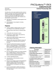
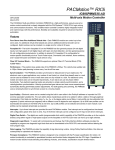
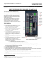
Two independent 10/100/1000 Ethernet LANs.
LAN1 attaches via the dedicated (upper) RJ-45
connector shown in Figure 1. LAN2 attaches via
the lower pair of internally-switched RJ-45
connectors.
Ethernet Global Data (EGD) Class 1 supported on
both LANs.
The embedded Ethernet interface is supported
by a dedicated microprocessor core. This
dedicated processing capability permits the CPU
Figure 1: CPE330 Features at a Glance
to support these two LANs with:
o up to 48 simultaneous SRTP Server connections,
o up to 16 simultaneous Modbus/TCP Server connections.
o 32 Clients are permitted; each may be SRTP or Modbus/TCP.
OPC UA Server with support for up to 5 sessions, 7 subscriptions per session, and up to 12,500 variables.
User may program in Ladder Diagram, Structured Text, Function Block Diagram, or C. Refer to PACSystems RX7i &
RX3i CPU Programmer's Reference Manual, GFK-2950.
Configurable data and program memory.
Supports auto-located Symbolic Variables that can use any amount of user memory.
Reference table sizes include 32k bits for discrete %I and %Q and up to 32k words each for analog %AI and %AQ.
Bulk memory (%W), up to max user memory, is also supported for data exchanges.
Supports up to 512 program blocks. Maximum size for a block is 128KB.
For supported I/O, Communications, Motion, and Intelligent modules, refer to the PACSystems RX3i System Manual,
GFK-2314.
Ability to display serial number and date code in PME Device Information Details.
indicates a trademark of GE Intelligent Platforms, Inc. and/or its affiliates. All other trademarks are the property of their respective
owners.
Copyright © 2015 General Electric Company. All Rights Reserved.
*
2
PACSystems* RX3i 1GHz 64MB CPU w/Ethernet
GFK-2942C
IC695CPE330-AAAD
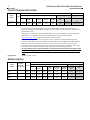
Current Release Information
Firmware Version (Build Number)
Catalog
Number
Date
IC695CPE330AAAD
Aug
2015
Upgrade Strategy:
Comment
Field Upgradeable
Not Field Upgradeable
Primary
OS
Loader
BOC
FPGA
Primary
µController
Primary
ACC402
EP Base
µController
Boot
BIOS
8.60
(E55G)
1.02
(E4OC)
1.19
(43A1)
1.171
(16A14)
1.6
(n/a)
2.20
(n/a)
1.2
(n/a)
0ACEE007
19-Mar-15
Feature
Enhancements
Firmware version 8.60 is being released as a field upgrade kit only.
Firmware version 8.60 adds support for Ethernet Global Data (EGD) and for the advanced
Ethernet configuration parameters necessary for EGD support, as documented in New Features
and Enhancements.
All versions of the CPE330 are field upgradeable to this firmware release using the upgrade kit
listed below. The upgrade is available via download from the GEIP support website
http://support.ge-ip.com. Product download number is DN4340.
The firmware upgrade process may take up to four minutes to complete depending on the
contents of the update. During the update, the RUN and OUTPUTS ENABLED LEDs blink GREEN
and the CPE330 may automatically reset one or more times. All LEDs will be off during the
automatic resets. The IC695ACC402 Energy Pack (if present) may also be updated. The energy
pack blinks all LEDs GREEN and performs an automatic reset following its update.
Do not manually power cycle the CPE330 or remove the Cap Pack from the Energy Pack base
(if present) during the updates as this may place the CPU in an unrecoverable and unusable
state.
Upgrade Kit:
41G2016-FW01-000-A3
Release History
Firmware Version (Build Number)
Catalog
Number
IC695CPE330AAAC
IC695CPE330AAAB
IC695CPE330AAAA
Bundled
w/ACC402
Energy Pack
IC695CPK330
Field Upgradeable
Date
June
2015
May
2015
Mar
2015
Not Field Upgradeable
Primary
OS
Loader
BOC
FPGA
Primary
µController
Primary
ACC402
EP Base
µController
Boot
BIOS
8.55
(E4YL)
8.50
(E4V9)
8.45
(E4P6)
1.02
(E4OC)
1.02
(E4OC)
1.02
(E4OC)
1.19
(43A1)
1.19
(43A1)
1.19
(43A1)
1.171
(16A14)
1.171
(16A14)
1.110
(11A12)
1.6
(n/a)
1.6
(n/a)
1.5
(n/a)
2.20
(n/a)
2.20
(n/a)
2.19
(n/a)
1.2
(n/a)
1.2
(n/a)
1.2
(n/a)
0ACEE007
19-Mar-15
0ACEE007
19-Mar-15
0ACEE007
19-Mar-15
PACSystems* RX3i 1GHz 64MB CPU w/Ethernet
3
IC695CPE330-AAAD
GFK-2942C
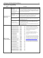
Functional Compatibility
Subject
Programmer Version
Requirements
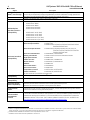
RX3i IO Module
Firmware Upgrade
Description
Feature
Minimum Version of PME Required
CPE330 EGD
Configuration – LAN2
Advanced Ethernet
Configuration Parameters
– LAN1 & LAN2
Proficy™ Machine Edition Logic Developer PLC 8.60 SIM 5 or later
is required for configuration of EGD on CPE330 LAN2. This version
is also required for advanced Ethernet configuration parameter
support on both LAN1 and LAN2.
CPE330 EGD
Configuration – LAN1
Proficy™ Machine Edition Logic Developer PLC 8.60 or later is
required for configuration of EGD on CPE330 LAN1. This version
(without SIM5) does not support EGD on CPE330 LAN2 or
advanced Ethernet configuration parameters for EGD.
CPE330 Configuration
Proficy™ Machine Edition Logic Developer PLC 8.60 or later is
required for native configuration support of the CPE330 and its
embedded Ethernet ports.
CPU315 & CPU320
Compatible Configuration
If the embedded Ethernet ports are not needed, older versions of
Proficy Machine Edition may be used to download a CPU320
configuration to the CPE330.
CPU315 configurations must first be migrated to CPU320, then
downloaded to CPE330.
File Name
41G1485-MS10-000-A2.zip
41G1485-MS10-002-A1.zip
41G1485-MS10-001-A2.zip
41G1485-MS10-003-A1.zip
82A1190-MS10-000-A2.zip
82A1191-MS10-000-A2.zip
41G1289-MS10-000-A2.zip
82A1726-MS10-000-A1.zip
41G1486-MS10-000-A2.zip
41G1486-MS10-001-A2.zip
44A753049-G03.zip
44A753281-G01.zip
44A753282-G01.zip
44A753283-G01.zip
41G1606-MS10-000-A2.zip
44A753277-G06.zip
44A753278-G06.zip
82A1512-MS10-000-A4.zip
82A1844-MS10-000-A0.zip
41G1836-MS10-001-A0.zip
41G2060-MS10-000-A1.zip
41G2076-MS10-000-A1.zip
44A753032-G16.zip
44A753029-G01.zip
41G1522-MS10-000-A0.zip
41G1522-MS10-000-A1.zip
44A753028-G02.zip
41G1520-MS10-000-A0.zip
41G1520-MS10-000-A1.zip
44A73033-G02.zip
41G1444-MS10-000-A6.zip
82A1790-MS10-000-A9.zip
82A1790-MS10-000-B0.zip
82A1729-MS10-000-A1.zip
82A1558-MS10-000-A4.zip
82A1845-MS10-000-A0.zip
41G1930-MS10-000-A0.zip
Module
ALG222
ALG223
ALG232
ALG233
ALG306
ALG312
ALG392
ALG412
ALG442
ALG542
ALG600
ALG704
ALG708
ALG728
APU300
CMM002
CMM004
CMX128
CMX128
ECM850
EDS001
EIS001
ETM001
MDL660
MDL664
MDL664
MDL754
MDL765
MDL765
PBM300
PMM335
PNC001
PNC001
PRS015
RMX128
RMX128
RMX228
Version
1.60
1.60
1.60
1.60
1.02
1.02
1.61
1.02
1.61
1.61
1.14
1.08
1.08
1.01
1.10
1.34
1.34
1.07
2.00
1.00
6.30
6.30
6.30
1.10
1.00
1.01
1.20
1.00
1.01
1.04
1.61
2.11
2.20
1.04
1.07
2.00
2.00
Notes
The CPE330 IO Module Firmware Upgrade
procedure is transacted over Ethernet using a
web browser and contains enhanced security
features. Instructions for this procedure are
included in the CPE330 upgrade kit
documentation.
The upgrade files listed here contain the
necessary security features to allow them to
work with the new enhanced security
procedure.
Older versions may not contain the necessary
security features to allow them to work with the
new enhanced security procedure. Should you
need to use an older version upgrade kit which
is incompatible, contact GE for assistance at
http://www.geautomation.com/how-can-we-help-you.
All future IO module firmware upgrade kits will
be compatible with the new security feature.
4
PACSystems* RX3i 1GHz 64MB CPU w/Ethernet
GFK-2942C
IC695CPE330-AAAD
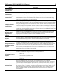
Subject
HART® Pass Through
USB
CFast
RX3i Backplane
Hardware Revision
Compatibility
Series 90-30 Module
Compatibility
IC694 (blue) Module
Compatibility
IC695 (PCI) Module
Compatibility
Description
HART Pass Through entails usage of PC-based applications, RX3i Analog modules with HART
functionality and (optionally) supporting PROFINET products. HART Pass Through operation is
described in the PACSystems HART Pass Through User Manual, GFK-2929.
CPE330 is compatible with USB 1.1 and USB 2.0 devices.
Cfast slot is not enabled in this release.
The following backplane hardware revisions MUST be used:
IC695CHS012-BAMP
IC695CHS016-BAMP
IC695CHS012CA-BAMP
IC695CHS016CA-BAMP
or
IC695CHS007-AA (or later)
IC695CHS012-CA (or later)
IC695CHS016-CA (or later)
IC695CHS012CA-CA (or later)
IC695CHS016CA-CA (or later)
The following Series 90-30 modules are supported by the PACSystems RX3i:
Discrete Input Modules:
IC693ACC300,
IC693MDL230/231/240/241/250/260/632/634/635/645
/646/648/654/655/6601
Discrete Output Modules:
IC693MDL310/330/340/350/390/730/731/732/733
/734/740/741/742/748/752/753/754/758
/760/916/930/931/940
Discrete Combinational:
IC693MAR590, IC693MDR390
Analog I/O Modules:
IC693ALG220/221/222/223/390/391/392/442
High Speed Counter:
IC693APU300
FANUC I/O Link:
IC693BEM320, IC693BEM321
Motion Control:
IC693DSM314, IC693DSM324
GENIUS:
IC693BEM331
Device Net Master:
IC693DNM200
Serial IO Processor:
IC693APU305
Temperature Control:
IC693TCM302, IC693TCM303
Power Transducer:
IC693PTM100, IC693PTM101
No other Series 90-30 modules are supported.
CPE330 supports all IC694* modules.1,2
CPE330 supports all IC695* modules.
Series 90-30 Main
Rack Compatibility
Series 90-30 Main Racks cannot be used in a PACSystems RX3i system.
Series 90-30 CPUs do not operate in PACSystems RX3i Racks.
Isolated 24Vdc
power
In applications that use the IC69xALG220/221/222, consult PACSystems RX3i System Manual,
GFK-2314 for details of wiring the 24Vdc power.
Recommended
IC200ALG240
revision
When a VersaMax™ system Genius® Network Interface Unit (IC200GBI001) interoperates with
a Genius Bus Controller located in a PACSystems PLC, and the VersaMax system contains an
IC200ALG240 Analog Input Module, it is recommended that the IC200ALG240 firmware be
updated to Revision 1.20 or later. Use firmware update kit 44A752313-G02, available here:
http://support.ge-ip.com/support/index?page=docchannel&id=DO506.
HART® is a registered trademark of the HART Communication Foundation of Austin, Texas USA. Any use of the term HART hereafter
in this document, or any document referenced by this document, implies the registered trademark.
1 IC693MDL660/IC694MDL660 firmware must be updated to version 1.10
2 IC694MDL754 firmware must be updated to version 1.10
®
PACSystems* RX3i 1GHz 64MB CPU w/Ethernet
5
IC695CPE330-AAAD
Subject
Configuration of
IC694MDL754
IC695CPE330
AC Power Supply
Compatibility
CPU315 & CPU320
Configuration
Compatibility
GFK-2942C
Description
Always configure sixteen bits of module status when using this module. Configuring zero bits
of module status will result in invalid data in the ESCP status bits of the module.
For new installations using AC power supplies, the CPE330 requires an IC695PSA040H or
IC695PSA140D (or higher) revision power supply to ensure compatibility.
For retrofit installations using AC power supplies, the CPE330 may require an IC695PSA040H or
IC695PSA140D (or higher) revision power supply depending on the total current load in the
backplane. If the total current load exceeds the minimum current threshold of the existing
power supply, no power supply change is required.
The CPE330 may be interchanged with a corresponding CPU320 with no upgrade to Proficy
Machine Edition (PME) software. Logic and configuration equality in PME are maintained when
storing the same project to either a CPU320 or a CPE330. Migration of CPU315 applications to
the CPE330 is possible with no upgrade to PME by converting them to a CPU320 application
and storing the project to the CPE330. Versions of PME with native CPE330 support allow either
a CPU320 or a CPE330 configuration to be stored to the CPE330. When a CPE330 is configured
as a CPU320, Ethernet properties cannot be configured however, the embedded Ethernet ports
may be used with the default IP Addresses.
Migration of CPU315
& CPU320 Serial
Applications to
CPE330
Applications using the embedded serial ports of the CPU315 or CPU320 should move serial
functionality to the IC695CMM002 or IC695CMM004 Serial Communication Modules when
migrating to the CPE330 since it does not have embedded serial ports.
Ethernet AUP File
Support
The CPE330 does not support Advanced User Parameter (AUP) files for its Embedded Ethernet
interfaces. AUP files are supported for external IC695ETM001 Ethernet modules.
Service Request 56 &
57 Logic Driven
Read/Write to Flash
Support
The IC695ACC402 Energy Pack automatically saves all user memory to flash when the CPE330
is powered off, and restores it to RAM when the CPE330 is powered on. Consequently, the
CPE330 does not support Service Requests 56 & 57 Logic Driven Read/Write to Flash. The ENO
output of the function block returns no power flow if these service requests are executed.
When migrating a CPU320 application that uses Service Requests 56 & 57 to a CPE330, the
IC695ACC402 Energy Pack needs to be attached.
Supported Browsers
for CPE330 Firmware
Update
The CPE330 supports secure firmware update over Ethernet using a web browser. Supported
browsers are listed below along with the minimum required version:
Firefox: 31.0
Chrome: 36.0.1985.143 m
Internet Explorer: 8.0.7601.17514
Opera: 23.0.1522.75
Safari: 7.0.5
CIMPLICITY
OPC UA Client
When using CIMPLICITY OPC UA Client with the CPE330, ensure the total number of
subscriptions does not exceed the maximum number of subscriptions per session supported
by the CPE330. (The CPE330 supports up to 5 sessions, 7 subscriptions per session, and up to
12,500 variables.) CIMPLICITY OPC UA Client is configured to create one subscription for every
500 items by default. If, for example, a project contains 1000 monitored items, CIMPLICITY will
create two subscriptions. The number of items per subscription may be modified from the
Device Configuration Panel / OPC UA DA Configuration / Subscriptions / Max. Number of
Monitored Items.
6
PACSystems* RX3i 1GHz 64MB CPU w/Ethernet
GFK-2942C
IC695CPE330-AAAD
Subject
CPE330 vs CPU320
Power Requirements
Description
When migrating a CPU320 application to a CPE330, the power consumption must be
recalculated to ensure adequate power is available in the new system. The maximum power
consumption of a CPE330 is 18W whereas the maximum consumption a CPU320 is 9.3W.
Depending on the total power available in the CPU320 system, it is possible that additional
RX3i power supplies will be required. Users may view the combined power consumption of an
RX3i rack in PME by right-clicking the power supply whose icon has a power usage indicator
and selecting properties.
CPE330 Power Requirements
CPU320 Power Requirements
0.0 A
1.0 A
0.0 A
1.2 A
0.625 A without Energy Pack
0.0 A
0.750 A with IC695ACC402 Energy Pack
+24only
Vdcenergy
Isolated:
A
0.0 A
The
pack 0.0
compatible
with the IC695CPE330 is the IC695ACC402.
+3.3 Vdc:
+5.0 Vdc:
+24 Vdc Relay:
PACSystems Energy
Pack Compatibility
Ethernet Station
Manager
Compatibility
The CPE330 is not compatible with the ICRXIACCEPK01 RXi Controller Energy Pack or the
IC695ACC400 CPE305/310 Energy Pack.
It is not physically possible to connect the CPE330 and the IC695ACC400 CPE305/310
Energy Pack together.
However, it is possible to connect the CPE330 and the ICRXIACCEPK01 RXi Controller
Energy Pack. Connecting the CPE330 to the RXi Energy Pack is not harmful. However, if
power is applied, the CPE330 will continuously reset and not power up. Should this occur,
turn the CPE330 off and disconnect the RXi Energy Pack.
It is possible to connect the ICRXIACCCPK01A RXi Capacitor Pack to the IC695ACC402
Energy Pack Base. If this occurs, the capacitor pack may take longer to charge and a
battery fault may be logged. Do not use the CPK01A RXi Capacitor Pack with the ACC402
Energy Pack Base.
It is also physically possible to connect the IC695ACC402 CPE330 Energy Pack and
IC695ACC412 Capacitor Pack to an ICRXICTL000 controller. If this occurs no errors are
logged. However the capacitors will reach their end-of-life threshold faster than the RXi
Capacitor Pack ICRXIACCCPK01. Do not use the CPE330 Energy Pack or Capacitor Pack
with the RXi Controller.
Ethernet Station Manager utility Version 1.3 Build 2 or later is recommended for use with the
CPE330. Earlier versions are compatible; however they may not display all CPE330 Ethernet
parameters after issuing a parm all command. Should this issue occur, pressing enter, or
issuing another command will cause the station manager to display the remaining
parameters.
Problems Resolved by this Revision
None.
PACSystems* RX3i 1GHz 64MB CPU w/Ethernet
IC695CPE330-AAAD
7
GFK-2942C
New Features and Enhancements
Ethernet Global Data (EGD) Class 1: Ethernet Global Data is data that is automatically sent from one Ethernet
device to one or more others. Once Ethernet Global Data has been configured, the data is sent automatically during
system operation. No program interaction is necessary to produce or consume the global data. The CPE330
supports production and consumption of unicast, multicast, and broadcast EGD exchanges on both the LAN1 and
LAN2 embedded Ethernet interfaces. Refer to GFK-2224P for a description of EGD Class 1.
Advanced Ethernet Configuration Parameters: Advanced Ethernet configuration parameters for Ethernet Global
Data applications may be selected directly in the CPE330 LAN1 and LAN2 Ethernet configuration tabs in Proficy
Machine Edition.
Previously, all RX3i Ethernet products required download of an AUP configuration file to set EGD advanced
parameters. The AUP file is not necessary (and is not supported) on the CPE330. Instead, use the PME configuration
tabs provided. See GFK-2224P for details of Advanced User Parameters configuration.
Refer to Functional Compatibility above for details of PME support.
Restrictions and Open Issues
Subject
ID code
Description
Firmware Update Login
Timeout
DE196
DE205
DE2626
The CPE330 enforces a two minute login activity timeout on the Firmware
Update web page. Selecting an update package on the Firmware Update
page and pressing the Upload File button after the timer expires initiates a
firmware update. However, instead of displaying the firmware update
status, one of these scenarios may occur:
Another login page is presented. After entering the user name and
password the update status is displayed.
The web browser loses connection with the CPE330 and is unable to
display update status because the CPU is automatically resetting
while applying the firmware update. After the reset completes,
pressing the refresh button in the browser shows the installed
firmware version.
These timeout issues may be avoided by having the firmware file ready so
that the firmware update can be initiated immediately after logging in.
Running applications with
fatal faults from flash
DE86
If an application that generates a fatal fault (such as a watchdog timeout)
is stored to flash, the controller is configured to power-up from flash and
go to RUN, and the RUN/STOP switch is disabled, the application may
become stuck in an endless loop. (Power-up from flash, go to RUN,
watchdog timeout, repeat.) Return the CPE330 to the factory if this
condition is encountered. It is recommended that users thoroughly test
their application before writing it to flash.
Clear All clears PLC_BAT
and masks Energy Pack
failures
DE715
A Clear All operation clears the values of all %S bits. After this operation
the PLC_BAT status bit value may not reflect the actual status of the
Energy Pack. For example, an Energy Pack in a failed state prior to the
Clear All operation will remain in the failed state after the Clear All.
Nonetheless, the PLC_BAT bit will indicate a good state as a result of the
Clear All operation. Remove the Cap Pack and reinstall it in order to
reassert the PLC_BAT status bit.
Using OEM Passwords with
Enhanced Security
Disabled
DE755
Single character OEM passwords are not supported when enhanced
security is disabled.
8
GFK-2942C
Subject
PACSystems* RX3i 1GHz 64MB CPU w/Ethernet
IC695CPE330-AAAD
ID code
Description
PME cannot display
reference tables with
Enhanced Security Enabled
and OEM Locked
DE781
When Enhanced Security is enabled and OEM protection is engaged, only
reference areas specified within the Access Control List can be viewed by
a programmer, or HMI, regardless of privilege level. For example, if viewing
%R memory from words 1 to 400 then the Access Control List must include
read access to %R words 1 to 400. A custom reference view table with
smaller reference sizes may also be used.
Controller Communication
Window Timer settings
below 10 ms are ignored
DE845
Normal sweep allows the configuration of the Controller Communications
Window Timer for Limited operation and a time range from 0 to 255 ms
(default 10 ms). However, the system is currently ignoring settings in the
0 to 9 ms range which results in an effective window time of 10 ms for this
configuration range. This means a sweep impact of up to 10 ms may
occur for some complex Controller Communication Window operations. If
this operation is undesired then it is recommended to use a different
sweep mode such as Constant Sweep or Constant Window.
Selecting Variable Publish
State = Internal causes
variable to be published in
Address Space
DE1330
PME allows users to select a Variables Publish State to Internal. In some
cases, this will cause the variable to be published to the OPC-UA address
space. The manual states users should select External Read/Write or
External Read-Only to publish to the address space. This is the
recommended approach.
OPC-UA Server Restart
Fails to complete
DE1326
The OPC-UA server may fail to restart after a large number (~200) of
restart sequences are attempted without an intervening power cycle. A
restart sequence will occur with the following operations: Run Mode or
Stop Mode Store when published variables change and OPCUA server is
running. Whenever this occurs, the server restart bit will stay on
indefinitely. The issue is contained to OPC-UA server operation only. Power
cycling the controller is the only way to address the issue.
CPE330 Firmware Update
and IE 11.0
DE2038
CPE330 firmware may be updated using Internet Explorer 11. In rare
instances, however, it is possible that the web page may not show
firmware update status. If this occurs, wait until the CPE330 OK LED is on
solid green indicating that the firmware update is complete, then click
refresh button in IE. The web page should refresh and show the new
firmware version.
Abrupt Power-down Fault
DE2256
An Abrupt power-down detected at power-up fault is recorded in the
CPE330 PLC Fault Table if both the Logic/Configuration Power-up Source
and Data Power-up Source in the hardware configuration are set to
Always Flash or Conditional Flash and the CPE330 is turned off without an
energy pack connected. This fault indicates that user memory was not
preserved across the power cycle and does not interfere with normal
operation because the application is already configured to power up from
flash if there is no energy pack connected.
Power Supply Loss of
Module Fault After
Configuration Download
DE2257
CR-6257
A Loss of, or missing option module fault may appear for any RX3i power
supply configured in the main rack whenever a hardware configuration
download is performed after a BOC update occurs. (A BOC update occurs
during a firmware update when switching between different CPU models
in a single backlpane and also the first time a particular CPU model is
placed in a backplane. BOC updates are indicated by the RUN and Output
Enabled LEDs blinking in unison briefly during power up.)
This issue does not affect normal operation and may be cleared by power
cycling the CPU.
PACSystems* RX3i 1GHz 64MB CPU w/Ethernet
IC695CPE330-AAAD
Subject
9
GFK-2942C
ID code
Description
Missing Addition of IOC
event, when ECM850
module restarts due to
reason like reset pushbutton and SVC_REQ 24
DE1248
When ECM850 module RESET is triggered using SVC_REQ 24 or via Reset
pushbutton, PLC CPU do not report Addition of IOC fault message in
Controller fault table, after successful reset of module.
Blink Code 1-2-1-8 After
Power On
DE2017
Rarely, after powering on, the CPE330 may display blink code 1-2-1-8 on
its LEDs. If this occurs, cycle power to the CPU to clear the condition.
Loss of IO Modules in
Expansion Rack
DE2336
Rarely, IO modules in an expansion rack may fail to reconfigure if the
expansion rack is turned off and back on while the main rack remains
powered on. If this occurs, turn the expansion rack off and back on again
or, download hardware configuration using PME.
ALG616, ALG626, & ALG628
Terminal Block Present
Status Bit
DE2422
IC695ALG616-Fx, IC695ALG626-Fx, and IC695ALG628-Fx (and later
hardware revision) analog modules may not set the terminal block present
status bit in their module status after a CPE330 firmware update
completes, even if the terminal block is installed. Normal operation of the
terminal block present status bit may be restored by performing one of the
following operations: removing and reinstalling the terminal block,
resetting the analog module using Service Request #24, or power cycling
the rack.
Ethernet COMMREQs not
always delivered on the
first logic sweep
ISS183540
In certain instances where User Logic is of sufficient size and a COMMREQ
is issued on first logic sweep, a race condition existing between
determination of the CPU Run/Stop state and logic-driven issuance of a
COMRREQ which may cause the COMMREQ to be aborted before its
transmission is attempted. To the user, it would appear as if the
COMMREQ was never issued. The condition is much more observable on
COMMREQs issued from the CPU’s embedded Ethernet port. To avoid the
possibility of encountering this condition, users should avoid issuing
COMMREQs on first logic sweep.
PMM335 loss is
occasionally detected on
power down of the
CPU. (Module is not lost on
power up.)
ISS182714
The PMM335 monitors power loss, independently of the CPU. The CPE305,
CPE310, CPU315, CPU320, CRU320, and CPE330 are fast enough that they
can occasionally detect and log the loss of the PMM335 just before the
CPU itself powers down.
No corrective action is required; This situation can be verified in two ways:
(1) by inspecting the timestamp in the loss-of-module report one can
correlate it with the power-down event, and (2) by performing a PME Show
Status Details report one can see that the PMM335 is present after power
up.
Hot Swapping some Analog
modules slowly result in
modules not being
recognized
CR-7365
Occasionally during a hot insertion (hot swap) of IC695 Non-Isolated
Analog Input Modules, input channels may take up to 2 seconds to reflect
actual input values after the module ok bit is enabled in the module status
word. This has only been seen when the hot insertion has been done
slowly (i.e. approximately 1.5 seconds to insert the module).
Ethernet Disconnect
During Word for Word
Change
CR-2234
If the Ethernet connection is broken during a word–for-word change, the
programmer may not allow a subsequent word-for-word change after
reconnecting due to the fact that it thinks another programmer is
currently attached. To correct the issue, go offline and then back online
again.
10
GFK-2942C
Subject
PACSystems* RX3i 1GHz 64MB CPU w/Ethernet
IC695CPE330-AAAD
ID code
Description
Simultaneous Clears,
Loads and Stores Not
Supported
CR-3118
CR-3300
Currently, PACSystems CPUs do not support multiple programmers
changing CPU contents at the same time. The programming software may
generate an error during the operation. Simultaneous loads from a single
PLC are allowed.
Hardware Configuration
Not Equal After Changing
Target Name
CR-3181
If the user stores a hardware configuration to flash that sets Logic/Config
Power up Source to Always Flash or Conditional Flash and then
subsequently changes the name of the target in the programming
software, the hardware configuration will go Not Equal and will not Verify
as equal.
PLC and IO Fault Tables
May Need to be Cleared
Twice to Clear Faulted
State
CR-3191
Both PLC and IO fault tables may need to be cleared to take the CPU out of
Stop/Fault mode. If one of the tables contains a recurring fault, the order
in which the tables are cleared may be significant. If the CPU is still in
Stop/Fault mode after both tables are cleared, try clearing the fault tables
again.
Setting Force On/Off by
Storing Initial Value
CR-3317
Once a Force On or Force Off has been stored to the PLC, the user cannot
switch from Force On to Force Off or vice-versa directly by downloading
initial values. The user can turn off the force by doing a download, and
then change the Force On or Force Off by another download.
Second programmer can
change logic while in Test
& Edit mode
CR-4223
While currently active in a Test and Edit session using Machine Edition on
one PC, Machine Edition running on another PC is not prevented from
storing new logic to the PLC.
Must Have Logic If
Powering-Up From Flash
CR-4633
If the application will configure the CPU to retrieve the contents of flash
memory at power-up, be sure to include logic along with hardware
configuration when saving to flash memory.
Two loss of module faults
for Universal Analog
Module
CR-5462
Occasionally, the hot removal of the Universal Analog Input Module
(IC695ALG600) results in two Loss of I/O Module faults instead of one.
Power up of Series 90-30
HSC module may take as
long as 20 seconds
CR-5666
As power is applied to a 90-30 High-Speed Counter, the module ready bit
in the status bits returned each sweep from the module may not be set for
as long as 20 seconds after the first PLC sweep, even though there is no
loss of module indication. I/O data exchanged with the module is not
meaningful until this bit is set by the module. Refer to pages 4-3 to 4-5 of
High Speed Counter Modules for PACSystems* RX3i and Series 90*-30
User’s Manual, GFK-0293D.
Informational fault at
power-up
CR-5850
Intermittently during power-up, an Informational non-critical CPU software
fault may be generated with fault extra data of 01 91 01 D6. This fault will
have no effect on the normal operation of the PLC. But, if the hardware
watchdog timer expires after this fault and before power has been cycled
again, then the outputs of I/O modules may hold their last state, rather
than defaulting to zero.
Extended Memory Types
for IO Triggers
CR-5952
CR-6319
%R, %W and %M cannot be used as IO triggers.
Possible PME inability to
connect
CR-6067
Infrequently, an attempt to connect a programmer to a PLC via Ethernet
will be unsuccessful. The normal connection retry dialog will not be
displayed. Rebooting the computer that is running the programmer will
resolve the behavior.
GBC30 may not resume
operation after power
cycle
CR-6167
In rare instances, a GBC30 in an expansion rack may not resume normal
operation after a power cycle of either the expansion rack or the main
rack.
PACSystems* RX3i 1GHz 64MB CPU w/Ethernet
IC695CPE330-AAAD
Subject
11
GFK-2942C
ID code
Description
Configuration of 3rd Party
Modules
CR-6207
When configuring a 3rd Party Module in PME, a non-zero reference length
must be assigned to at least one reference type. For example, assign eight
bits of %I. Do not specify a length of zero for all reference types since this
will cause the module to not function properly in the system.
Power supply status after
power cycling
CR-6294
Rarely, turning a power supply on or off may not result in an add or loss
fault. Also, the slot will appear empty in the programmer’s online status
detail view. The power supply continues to operate normally. Power cycle
to restore normal status reporting.
Don’t use multiple targets
CR-6450
In a system in which the hardware configuration is stored from one target
and logic is stored from a different target, powering-up from flash will not
work. The observed behavior is that, following a power up from flash, PME
reports hardware configuration and logic not equal.
Missing Loss of terminal
block fault
CR-6526
The IC695ALG600/608/616 analog input modules do not produce a Loss of
terminal block fault when hardware configuration is stored or the module
is hot-inserted, and the terminal block is not locked into place.
Sequence Store Failure
CR-6586
ISS176888
When downloading projects with very large hardware configuration or
which use large amounts of user memory, it is possible to encounter a PLC
Sequence Store Failure error when writing the project to flash. To work
around this error, either or both of the following actions may be helpful:
1. Perform an explicit clear of flash prior to performing the write.
2. Increase the operation timeout used by PME prior to performing the
write. This is done by expanding the Additional Configuration in the
Inspector window for the target controller, and adjusting the Request
Timeout. The timeout may need to be increased to as much as
60000 ms, depending on the amount of memory used and the
condition of the flash memory.
IC695ALG600 Lead
Resistance Compensation
setting
CR-6689
A configuration store operation will fail if a channel is configured for 3-wire
RTD and Lead Resistance Compensation is set to Disabled. A Loss of
Module fault will be logged in the I/O Fault table at the end of the store
operation. To recover the lost module, the configuration must be changed
to enable Lead Resistance Compensation and module must be power
cycled.
C Toolkit PlcMemCopy
Documentation Incorrect
CR-7082
This routine does allow the destination and source pointers to be outside
of reference memory. If the destination points to discrete reference
memory, overrides and transitions will be honored. Note that the header
for PlcMemCopy has been updated in Release 3.50 of the C toolkit.
Logic and HWC not equal
after power cycle
ISS168431
If the Hardware Config from Target 1, with Logic/Configuration Power-up
Source and Data Source both set to Always from Flash, is stored in Flash,
then Logic and Hardware Config from Target 2, with Logic/Configuration
Power-up Source both set to Always from RAM, are stored to RAM and
there is a good battery, then when power is cycled the programmer may
show that Logic and Hardware Config are not equal. The remedy is to
clear Flash and re-store the Logic and Hardware Config from Target 2.
Multiple Log Events
CR-2014
The Ethernet Interface sometimes generates multiple exception log events
and PLC Fault Table entries when a single error condition occurs. Under
repetitive error conditions, the exception log and/or PLC Fault Table can be
completely filled with repetitive error messages.
12
PACSystems* RX3i 1GHz 64MB CPU w/Ethernet
GFK-2942C
Subject
ID code
Description
IC695CPE330-AAAD
Spurious Ethernet Fault
CR-4104
In rare instances, after power cycle, the Ethernet Interface may log the
following fault, Event = 28H, Entry 2 = 000eH. This fault can be safely
ignored.
Clear of large hardware
configurations may cause
log event 08/20
CR-6577
A Log event 08/20 may occur when very large hardware configurations
are cleared and transfers are active on other Server connections. This log
event can be safely ignored.
PLC response timeout
errors (8/08) in Ethernet
exception log under
extremely heavy SRTP
traffic
ISS010006
Under extremely heavy SRTP traffic conditions, the Ethernet Interface may
log an event in the Ethernet exception log (Event 8, Entry 2 = 08H)
indicating an overload condition. This error terminates the SRTP
connection. If this event appears, either the traffic load should be
reduced, or the application should use an alternate communications
method to verify that critical data transfers were not lost due to the
overload.
SRTP channel transfers
may take up to 20 seconds
after power cycle
ISS155214
When SRTP communications are interrupted by a power cycle, the
Ethernet interface may require up to 20 seconds to reestablish TCP
connection used for SRTP communications.
Intermittent Ethernet log
event 8H/15H after power
cycle
ISS163056
When starting after a power cycle, the Ethernet Interface may
intermittently log an exception (entry 8H, Entry 2 = 15H, Entry 3 = 0000H,
Entry 4 = 00aaH). This exception is benign and may be ignored.
RDSD upload / unintended
OEM protection lock
ISS182099
When an OEM key is set in a controller, and the controller is unlocked, if an
RDSD upload is performed, in rare occasions OEM protection will be
unintentionally locked after the upload completes. To recover, enter OEM
password to unlock the project, then clear the user memory and flash
memory.
Operational Notes
Subject
Description
Default IP Addresses for
CPE330 Embedded
Ethernet
Initial Ethernet communication with the CPE330 may be accomplished using the default IP
Addresses programmed at the factory:
LAN1 (Top Ethernet Port)
LAN2 (Bottom Two Ethernet Ports)
IP Address:
192.168.0.100
10.10.0.100
Subnet Mask:
255.255.255.0
255.255.255.0
Gateway:
0.0.0.0
0.0.0.0
Connecting to CPE330
Embedded Ethernet
when IP Addresses are
not Known
If the IP Addresses of the CPE330 embedded LAN1 and LAN2 Ethernet interfaces are not
known, communication may be established using these methods to set new IP Addresses:
Set a temporary IP Address using the Set Temporary IP Address utility in Proficy Machine
Edition. (PME) After setting the temporary address, connect to the CPE330 using PME
and download a new hardware configuration with the desired permanent IP Addresses.
(The IP Address set by the Set Temporary IP Address utility is temporary and is reset to
match the stored configuration after a power cycle. After using the utility, a permanent
IP Address must be set by storing a hardware configuration.)
Connect to the CPE330 with PME using an IC695ETM001 module with a known
IP Address. Download a new hardware configuration with the desired IP Addresses for
the CPE330 embedded Ethernet interfaces.
PACSystems* RX3i 1GHz 64MB CPU w/Ethernet
IC695CPE330-AAAD
Subject
Set Temporary IP
Address Utility
Limitations
13
GFK-2942C
Description
These limitations apply when using the Set Temporary IP Address utility in Proficy Machine
Edition (PME) with the CPE330. Refer to PME’s help for a complete list of limitations:
The Set IP utility supports communication through network switches and hubs.
Communication through routers is not supported.
The current user logged on the development computer must have full administrator
privileges and PME must be run as an administrator.
The target controller must be located on the development computer’s local subnet, as
specified by the computer’s subnet mask and the IP address of the computer and
controller.
The Set IP utility does not always work on Windows 7 SP1. Refer to PME’s help for
possible work-arounds.
The Set IP utility is not compatible with USB to Ethernet adapters.
Ethernet Event Log Not
Preserved Across Power
Cycle
The CPE330 Ethernet event log for its embedded Ethernet interfaces is not maintained
across a power-cycle. Ethernet log events will be reported in the PLC Fault Table as with
other RX3i CPUs. The PLC Fault Table entries will be preserved if an energy pack is attached.
Station Manager
Commands
The embedded Ethernet interfaces of the CPE330 support a subset of Station Manager
Commands (monitor only commands). Refer to PACSystems TCP/IP Ethernet
Communications Station Manager Manual, GFK-2225, for details.
Programmer Display of
Module Information
The functionality to display module status in Proficy™ Machine Edition Logic Developer will
show 5CPE330A when the CPE330 is configured as a CPU320.
RDSD / Programmer
Interaction
When using RDSD, all Proficy™ Machine Edition Logic Developer PLC connections must be in
the Offline state for the RDSD to function properly.
RDSD OEM / Password
Protection of Former
Uploads Incorrectly
Maintained
When deleting an OEM key from a project, you must remove the Energy Pack and cycle
power before writing to the RDSD. If this procedure is not followed there are rare occasions
where the OEM key that had been deleted may be restored on the RDSD device and
therefore could be unexpectedly downloaded to the CPU on a subsequent RDSD download.
Extra Option Module
Fault after Downloading
CPU320 Configuration
to CPE330
An Extra Option Module fault is logged in the Controller Fault Table after downloading a
CPU320 configuration to a CPE330. This indicates that the Embedded Ethernet interface did
not receive a configuration. This fault is expected and does not interfere with normal
controller operation.
CPE330 Power-up Time
The CPE330 requires more time to power up than the CPU320:
When an IC695ACC402 Energy Pack is not connected, the CPE330 requires
approximately 30 seconds to complete power-up. The CPU OK, RUN, and OUT EN LEDs
remain off for up to 30 seconds after power is applied.
When an energy pack is connected, the CPE330 requires up to 90 seconds to complete
power up. The power up sequence of the CPE330 begins after the energy pack is fully
charged. Charging may require up to 60 seconds depending on the capacitor pack’s
initial charge. (The energy pack’s STAT LED blinks green while it is charging and turns
solid green when charging is complete.)
Hot swap of Cap Pack
during firmware update
results in RXi controller
fatal indication (i.e.,
blink code)
Insertion or removal of the Energy Pack Cap Pack during an Energy Pack firmware update
will cause the CPE330 to become non-responsive. In order to recover from this condition
user must cycle power to the CPE330. The CPE330 controller will enter a fatal blink trap with
code 0x2825.
Insertion of Cap Pack
during controller
power-up could cause
failed battery fault
If the Energy Pack is powered on without a Cap Pack and a Cap Pack is then inserted during
power-up of the CPE330, the CPE330 could log a failed battery fault. The CPE330 expects
the Energy Pack to report fully charged within a certain amount of time. This time limit may
not be met if the Cap Pack is absent at power up.
14
GFK-2942C
Subject
Avoid Overlapping IP
Subnets when
Configuring CPE330 IP
Address and Subnet
Mask
PACSystems* RX3i 1GHz 64MB CPU w/Ethernet
IC695CPE330-AAAD
Description
The CPE330 contains two LAN interfaces, each one supporting a unique IP Address. Care
must be taken when assigning IP Addresses and subnet masks to each LAN so that an
overlapping IP subnet is not created. Intermittent or no Ethernet communication may result
if an overlapping IP subnet is created and the two interfaces are NOT connected (cabled) to
the same physical network.
By default PME prohibits configuring both LAN interfaces on an overlapping IP subnet. (This
may be changed by going to Controller General Options and changing the CPE330 – LAN1,
LAN2 On Same Subnet to Show as Warning.)
Avoid Overlapping
Remote IP Networks
when Configuring
CPE330 IP Address and
Subnet Mask
The CPE330 network interface behaves like a single ETM001 with two LANs / IP Addresses.
(It is a multi-homed device.) Care must be taken when assigning IP Addresses and subnet
masks to each LAN so that each network does not overlap any remote subnets in the
network infrastructure. Intermittent or no Ethernet communication may result if the local
networks on the CPE330 overlap a remote subnet.
CPE330 Ethernet
Gateway Operation
The CPE330 allows configuration of an Ethernet gateway on both LAN1 and LAN2. Since the
CPE330 contains two LAN interfaces, each one supporting a unique IP Address, only one
gateway is active at a time:
If a gateway is configured on only one of the two LAN interfaces and the other is not
configured (0.0.0.0) then, the single gateway is shared by both interfaces.
If a gateway is configured on both LAN interfaces, then the LAN1 gateway is given
priority over the LAN2 gateway as long as LAN1 is functional. If, for example, the LAN1
cable is disconnected then the CPE330 will use the LAN2 gateway as a backup.
LAN1 and LAN2 LED
Network Speed
Indicators
The LAN1 and LAN2 network speed indication LEDs embedded in the RJ-45 Ethernet ports
of the CPE330 use different colors to indicate 1 Gbps data rate. The LAN1 LED is Amber to
indicate a data rate of 1 Gbps; the LAN2 LED is Green.
CPE330 Embedded
Ethernet Protocols &
Performance
The CPE330 has two independent Ethernet LANs with three auto-negotiating, full-duplex
10/100/1000 Ethernet Ports which allow support of two IP Addresses and the following
protocols:
OPC UA Server with support for up to 5 sessions, 7 subscriptions per session, and up to
12,500 variables
SRTP Server with support for up to 48 simultaneous connections
Modbus/TCP Server with support for up to 16 simultaneous server connections
SRTP and Modbus/TCP Client with support for up to 32 clients; each may be SRTP or
Modbus/TCP
Ethernet Global Data (EGD) Class 1
Embedded Ethernet communication is managed by a dedicated processor core.
Applications using Ethernet communication should be validated to ensure adequate
throughput is available to meet the needs of the application. Additional IC695ETM001
Ethernet modules may be added to the system if additional throughput is required.
CPE330 Multicast EGD
Exchange Operation:
Double Consumption
Possibility
In the event that LAN1 and LAN2 are physically connected to the same Ethernet network,
then any multicast EGD consumer exchanges may be consumed twice if both CPE330 LAN
interfaces use the same multicast IP addresses.
This double consumption occurs because the CPE330 has two LAN interfaces and it is
possible for the CPU to receive duplicate multicast packets (one from each interface) and
consume both. If this occurs, issuing a stat g station manager command shows that the
multicast consumer exchange updates twice as fast as the producer sends it.
To avoid this issue, connect the LAN1 and LAN2 to physically separate Ethernet networks
(i.e. no Ethernet switches in common).
PACSystems* RX3i 1GHz 64MB CPU w/Ethernet
IC695CPE330-AAAD
Subject
15
GFK-2942C
Description
The following apply generically to any RX3i CPU:
SRTP or Modbus
Channel COMMREQ
Error Response with
Gateway
SRTP & Modbus TCP Channel commands on RX3i CPUs with embedded Ethernet
(IC695CPE3xx) and the IC695ETM001 RX3i Ethernet module provide different COMMREQ error
codes whenever a request is sent to an unreachable server. When an Ethernet gateway is
configured, the COMMREQ returns error code 0290H; when a gateway is not configured, the
COMMREQ returns error code AA90H.
Cannot Clear
Controller Passwords
Loaded in Flash
WARNING: Passwords loaded to Flash (including OEM Password) cannot be cleared using
clear Flash or by downloading new firmware. Users MUST document the password as it is
not possible for the user to restore a unit to the default, no passwords condition (NULL).
OEM Protection not
enforced on power-up
from User Flash unless
engaged before power
cycle.
The OEM Protection Lock must be explicitly set before power down in order to ensure the
OEM lock will be set on power-up regardless of the type of security being used.
When passwords are
set with Enhanced
Security, connecting
with PME or
establishing SRTP
connections can cause
a temporary increase
in sweep times.
Due to the complex math involved with Enhanced Security authentication, creating SRTP
connections and changing privilege levels will take additional sweep time (several
milliseconds) not required when passwords are set with legacy security. If consistent sweep
time is important to the application, then it is recommended to configure the sweep mode for
Constant Sweep. Alternately, Constant Window or a Normal Sweep with both Limited
Backplane Window and Limited Controller Comm Windows can be configured. These sweep
modes will limit the sweep impact of Enhanced Security authentication and result in
authentication processing across multiple sweeps.
C Toolkit Application
Compatibility
Beginning with Rel 7.00 of the C Toolkit, writes to %S memory will now fail to compile where
in previous releases a compilation warning was issued. This affects use of the GE-supplied
C Toolkit macros Sw(), Si(), and Sd().
For firmware version 6.70 and later, the RUN LED for remote/expansion racks will reflect the
current IO enable/disable state (even when there are no output modules in the expansion
rack).
RUN LED for remote/expansion rack with input modules only will work as follows for All
versions prior to version 6.70:
When a remote or expansion baseplate is used with the RX3i, the RUN LED on the Series 9030 power supply for that baseplate is illuminated when the system is in Run mode only if the
rack contains at least one output module. If the rack contains input modules only, the RUN
LED is not illuminated. This is due to the way input modules are managed in the PACSystems
design and does not indicate an error.
RUN LED is not
illuminated on the
Series 90-30 power
supply for an RX3i
remote/expansion
rack with input
modules only
Undefined Symbols in
C Blocks
In Release 5.00 or later, if an attempt is made to download a C block containing undefined
symbols, the download will fail. Machine Edition will display the following message in the
Feedback Zone: Error 8097: Controller Error – Controller aborted the request [0x05][0xFF]
Prior to Release 5.00, C blocks containing undefined symbols could be successfully
downloaded, but if they were executed the CPU would transition to Stop/Halt mode.
16
PACSystems* RX3i 1GHz 64MB CPU w/Ethernet
GFK-2942C
Subject
IC695CPE330-AAAD
Description
Slot numbering, power 1. The A/C Power-Supply (IC695PSA040) for the RX3i is a doublewide module whose connector is
supply placement, CPU left justified as viewed when installed in a rack. It cannot be located in Slot 11 of a 12-slot rack
nor Slot 15 of a 16-slot rack. No latch mechanism is provided for the last (right-most) slot in a
placement and
rack, therefore it is not possible to place the power-supply in the second to last slot.
reference
2. The doublewide RX3i CPUs are modules whose connector is right justified as viewed when
installed in a rack. They are referenced for configuration and by user logic applications by the
leftmost slot that it occupies. For example, if one of these modules has its physical connector
inserted in to slot 4, which means it occupies slots 3 and 4, the CPU is referenced as being
located in slot 3. The referenced location of the CPU is not determined by what slot the
physical connector is located in, but rather by the left most slot occupied by the entire
module.
3. Due to item #2 above, a doublewide RX3i CPU may be located in Slot 0 of a rack (physical
connector in Slot 1). In addition the CPU cannot be located in Slot 11 of a 12-slot rack nor Slot
15 of a 16-slot rack, since doing so would require the physical connector to be located in the
slot reserved for an expansion module.
4. When migrating a Series 90-30 CPU system to a PACSystems RX3i CPU, be aware that to
maintain the Slot 1 location of the CPU, only a singlewide power-supply may be used in Slot 0.
Either DC power supply can be used (IC695PSD040 or IC695PSD140). Therefore, if the
application using an existing Series 90-30 system must maintain a Slot 1 CPU and uses an AC
power-supply, the RX3i system must have the RX3i AC power-supply located in a slot to the
right of the RX3i CPU in Slot 1.
5. In deciding to place the CPU in slots other than Slot 1, the user should be aware of the
possible application migration issues that could arise. The following lists the areas that could
be affected when migrating an application from one CPU slot to another.
User Logic
H/W
Configuration
Fault Tables
External
Devices
Item Affected
Service Request #15
(Read Last-Logged Fault
Table Entry)
Service Request #20
(Read Fault Tables)
Communications Request
(COMMREQ)
How Affected
Location of CPU faults will not be the standard 0.1
location, but will reflect the slot the CPU is located in.
User logic that decodes fault table entries retrieved by
these service requests may need updating.
COMMREQs directed to the CPU (e.g. those directed to the
serial ports of the CPU) will need to be updated with the
correct CPU slot reference.
CPU Slot location
Slot location of the CPU must be updated in the HW
Configuration to reflect the CPU’s true location.
Faults logged for the CPU
The location of faults logged for the CPU in the fault table
will not be the standard 0.1 (rack.slot) location, but will
reflect the CPU’s actual slot.
Series 90 PLCs
Remote Series 90 PLCs that use SRTP Channels COMMREQs expect the CPU to be in
slot 1. In order to support communications with Series 90 SRTP clients such as Series
90 PLCs using SRTP Channels, the RX3i internally redirects incoming SRTP requests
destined for {rack 0, slot 1} to {rack 0, slot 2}, provided that the CPU is located in rack 0
slot 2 (and the remote client has not issued an SRTP Destination service on the
connection to discover the rack and slot of the CPU). This special redirection permits
Series 90-30 applications that expect the power supply to be located leftmost and the
CPU to be located to the right of the power supply to function. Attempts to establish
channels with CPUs in slots other than 1 or 2 will fail if initiated from Series 90 PLCs.
HMI and External Communication Devices
All external communication devices that interact with the CPU should be checked for
compatibility with CPU slot locations other than slot 1. Problems may arise with, but
are not limited to, initial connection sequences and fault reporting. Machine Edition
View customers should select GE SRTP as their communications driver – it can
communicate with a CPU in any slot.
Host Communications Toolkit (HCT)
Applications that utilize the Host Communications Toolkit may require updated drivers.
PACSystems* RX3i 1GHz 64MB CPU w/Ethernet
IC695CPE330-AAAD
Subject
17
LD-PLC operations
GFK-2942C
Description
Machine Edition LD-PLC no longer supports a function that connects to the PLC, downloads,
and then disconnects from the PLC. The connect and download functions are now separate.
To perform a download to the PLC, you must first connect to the PLC.
Logic Executed in Row
Major instead of
Column Major
Logic execution in PACSystems RX3i is performed in row major order (similar to the Series 9030). This is different from the Series 90-70 that executes in column major order. This means
that some complicated rungs may execute slightly differently on PACSystems RX3i and Series
90-70. For specific examples, see the programming software on-line help.
NaN Handled
Differently than in
S90-30
The PACSystems RX3i CPU may return slightly different values for Not A Number as
compared to Series 90-30 CPUs. In these exception cases (e.g., 0.0/0.0), power flow out of the
function block is identical to Series 90-30 operation and the computed value is still Not A
Number.
PID Algorithm
Improved
The PID algorithm used in PACSystems has been improved and therefore PID will function
slightly differently on PACSystems RX3i than on the Series 90-30. The differences are that the
elapsed time is computed in 100 μS instead of 10 mS units. This smoothes the output
characteristic, eliminating periodic adjustments that occurred when the remainder
accumulated to 10mS.
Also, previous non-linear behavior when the integral gain is changed from some value to 1
repeat/second was eliminated.
Service Requests 6, 15, and 23 have slightly different parameters. Refer to PACSystems
RX7i & RX3i CPU Programmer's Reference Manual, GFK-2950.
PACSystems PLCs support Service Request 26/30 functionality via fault locating
references.
Service Request 13 requires a valid value in the input parameter block (Refer to
PACSystems RX7i & RX3i CPU Programmer's Reference Manual, GFK-2950 for details). On
the Series 90-30 and Series 90-70 the parameter block value was ignored.
Service Requests 48 and 49 are no longer supported (there is no auto-restart) because
most faults can be configured to be not fatal.
IL and SFC are not available.
Some Service Requests
different from 90-30 or
no longer supported
IL and SFC
DO I/O Instruction
The Series 90-30 Enhanced DO I/O instruction is converted to a standard DO I/O instruction
(the ALT parameter is discarded and ignored.)
END Instruction
The Series 90-30 END instruction is not supported. Alternate programming techniques should
be used.
Non-nested JUMP,
LABEL, MCR, &
ENDMCR Instructions
Non-nested JUMPs, LABELs, MCRs, & ENDMCRs are translated to the corresponding nested
JUMPs, LABELs, MCRs, & ENDMCRs when converting from Series 90-30 to PACSystems RX3i.
Changing IP Address
of Ethernet Interface
while Connected
Storing a hardware configuration with a new IP Address to the RX3i while connected via
Ethernet will succeed, then immediately disconnect because the RX3i is now using a different
IP Address than the Programmer. You must enter a new IP Address in the Target Properties in
the Machine Edition Inspector window before reconnecting.
Timer Operation
Care should be taken when timers (ONDTR, TMR, and OFDTR) are used in program blocks that
are NOT called every sweep. The timers accumulate time across calls to the sub-block unless
they are reset. This means that they function like timers operating in a program with a much
slower sweep than the timers in the main program block. For program blocks that are
inactive for large periods of time, the timers should be programmed in such a manner as to
account for this catch up feature.
Related to this are timers that are skipped because of the use of the JUMP instruction. Timers
that are skipped will NOT catch up and will therefore not accumulate time in the same
manner as if they were executed every sweep.
18
GFK-2942C
Subject
Constant Sweep
PACSystems* RX3i 1GHz 64MB CPU w/Ethernet
IC695CPE330-AAAD
Description
Constant Sweep time, when used, should be set at least 10 ms greater than the normal
sweep time to avoid any over-sweep conditions when monitoring or performing on-line
changes with the programmer. Window completion faults will occur if the constant sweep
setting is not high enough.
Large Number of
COMMREQs sent to
Module in one sweep
Causes Faults
A large number of COMMREQs (typically greater than 8) sent to a given board in the same
sweep may cause Module Software faults to be logged in the PLC fault table. The fault group
is MOD_OTHR_SOFTWR (16t, 10h) and the error code is COMMREQ_MB_FULL_START (2). When
this occurs, the FT output of the function block will also be set. To prevent this situation,
COMMREQs issued to a given board should be spread across multiple sweeps so that only a
limited number (typically 8 or less) of COMMREQs are sent to a given board in each sweep. In
addition, the FT output parameter should be checked for errors. If the FT output is set
(meaning an error has been detected), the COMMREQ could be re-issued by the application
logic.
C Block Standard Math
Functions Do Not Set
errno
In C Blocks, standard math functions (e.g. sqrt, pow, asin, acos) do not set errno to the correct
value and do not return the correct value if an invalid input is provided.
Hot Swap
Hot Swap of power supplies or CPUs is not supported
Run Mode Store of EGD
RX3i peripheral Ethernet modules (IC695ETM001) must be running firmware version 6.00 or
greater to utilize the Run Mode Store of EGD feature.
Proper IP Addressing is
Always Essential
The PACSystems Ethernet Interface must be configured with the correct IP Address for proper
operation in a TCP/IP Ethernet network. Use of incorrect IP Addresses can disrupt network
operation for the PACSystems and other nodes on the network. Refer to PACSystems RX7i &
RX3i TCP/IP Ethernet Communications User Manual, GFK-2224 for important information on
IP Addressing. When storing a new HW configuration to the RX3i, be sure that the HW
configuration contains the proper Ethernet addressing data (IP Address, Subnet Mask, and
Gateway IP Address) for the RX3i.
Note: Machine Edition programming software maintains the target IP Address (used to
connect the programmer to the target) independent of the contents of the HW Configuration
for that target). The target IP Address is set in the Target Properties in the Machine Edition
Inspector window. Storing a HW Configuration whose Ethernet addressing data contains an
IP Address that is different from the RX3i target IP Address will change the IP Address used by
the target RX3i as soon as the Store operation is completed; this will break the Programmer
connection. Before attempting to reconnect the Programmer, you must change the target IP
Address in the Target Properties in the Machine Edition Inspector window to use the new IP
Address. To regain communication at the former IP Address, use the manual corrective
action described above.
Storing a HW Configuration containing an incorrect Ethernet addressing data to the
PACSystems RX3i will result in loss of the Programmer connection and will require manual
corrective action as described above.
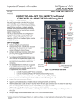
Network Architecture
and Overload
The hub or switch connections in an Ethernet network must form a tree and not a ring;
otherwise duplication of packets and network overload may result. In this situation, the RX3i
Ethernet modules will continually reset.
Caution
The hub or switch connections in an Ethernet network must form a
tree and not a ring; otherwise duplication of packets and network
overload may result
Reporting of Duplicate
IP Address
The PACSystems RX3i does not log an exception or a fault in the PLC Fault Table when it
detects a duplicate IP Address on the network.
SRTP Connections
Remain Open after IP
Address Changed
The Ethernet Interface does not terminate all open SRTP connections before changing its
IP Address. Once the local IP Address has changed, any existing open TCP connections are
unable to normally terminate. This can leave SRTP connections open until their underlying
TCP connections time out.
PACSystems* RX3i 1GHz 64MB CPU w/Ethernet
IC695CPE330-AAAD
Subject
Send Information
Report (COMMREQ
2010) requests may
fail at minimum
intervals less than 200
ms from embedded
Ethernet port.
Modbus/TCP Client
Channels require at
least a 10 ms delay
between bulk channel
close and bulk channel
open processing
Lengthy CPE
Backplane Operations
Incorrect COMMREQ
Status for Invalid
Program Name
FANUC I/O Master and
Slave operation
Lost count at power up
for Serial IO Processor
COMMREQ Status
Words Declared in Bit
Memory Types must
be Byte-Aligned
19
GFK-2942C
Description
Send Information Report COMMREQ requests, with a minimum interval between host
accesses of 200 ms or less, may fail if issued from the CPU’s embedded Ethernet port. A
COMMREQ Status Word value of 0290H, Period expired before transfer completed; still waiting
on transfer indicates this condition occurred. To work around this issue, the user can set the
minimum interval between host accesses to a value greater than 200 ms if issuing a Send
Information Report COMMREQ from the embedded Ethernet port of the CPU.
On CPUs with embedded Ethernet ports, a delay of at least 10 ms must occur between logicdriven attempts to close sixteen Modbus/TCP Channels simultaneously and then re-open
sixteen Modbus/TCP Channels. This delay is necessary to provide external Modbus/TCP
Servers sufficient time to close all channels before the Client issues channel open requests.
Some exceptionally lengthy CPE backplane operations, such as MC_CamTableSelect, Data
Log, and Read Event Queue functions, will take longer to complete compared to other RX3i
CPU models, and may delay backplane operations to IC695 modules.
For example, when an MC_CamTableSelect function block is executed on the PMM335
module, the CPU’s acknowledgement of the PMM355 module interrupt may be delayed. In
this situation, you may see the following fault in the I/O Fault Table, even when the interrupt
has not been dropped: Error initiating an interrupt to the CPU.
The program name for PACSystems is always LDPROG1. When another program name is
used in a COMMREQ accessing %L memory, an Invalid Block Name (05D5) error is generated.
Scansets on the master do not work properly for the first operation of the scanset after
entering RUN mode. They do work properly for subsequent scans.
After downloading a new hardware configuration and logic, a power cycle may be required
to resume FANUC I/O operation.
Use PLCs of similar performance in FANUC I/O networks. If a master or slave is located in an
RX3i system, the other PLCs should be RX3is or Series 90-30 CPU374s.
Repeated power up/down cycles of an expansion rack containing FANUC I/O slaves may
result in failure of the slaves’ operation, with the RDY LED off.
The Serial IO Processor (IC693APU305) will lose the first count after every power up or every
time the module receives a config
In previous releases, the CPU allowed configuration of COMMREQ Status Words in bit
memory types on a non-byte-aligned boundary. Even though the given reference was not
byte-aligned, the firmware would adjust it the next-lowest byte boundary before updating
status bits, overwriting the bits between the alignment boundary and specified location. To
ensure that the application operates as expected, release 3.50 requires configuration of
COMMREQ Status Words in bit memory types to be byte-aligned. For example if the user
specified status bit location of %I3, the CPU aligns the status bit location at %I1. Release 3.50
firmware requires the user to specify the appropriate aligned address (%I1) to ensure that the
utilized location is appropriate for their application. Note that the actual reference location
utilized is not changed, but now is explicitly stated for the user.
20
GFK-2942C
Subject
STOP and RUN Mode
Transition Priority
Suspend IO Function
Block does not
Suspend EGD
Nuisance Faults
Sometimes Logged for
Missing Power Supply
Uploaded Controller
Supplemental Files
lose date and time
PACSystems* RX3i 1GHz 64MB CPU w/Ethernet
IC695CPE330-AAAD
Description
The PACSystems CPU receives requests to change between stop and run mode from many
different sources. These include (but are not limited to) Proficy Machine Edition, HMIs, the user
application, and the RUN/STOP switch. Since there are many potential sources for a mode
change request, it is possible to receive a new mode change request while another is already
in progress. When this scenario occurs, the CPU evaluates the priority of the new mode
change request with the mode change that is in progress. If the new mode change request
has an equal or higher priority than the one already in progress, the CPU transitions to the
new mode instead of the one in progress. If, however, the new mode change request has a
lower priority than the one in progress, the new mode request is discarded and the CPU
completes the mode change that is in progress. The sweep mode priorities are (listed from
highest to lowest priority) STOP HALT, STOP FAULT, STOP, and RUN. (NOTE: The IO
ENABLED/DISABLED state is not part of the mode priority evaluation.) For example, a CPU is in
RUN IO ENABLED mode and a Service request 13 function block is executed to place the CPU
into STOP IO DISABLED mode. Before the transition to STOP IO DISABLED is completed, the
RUN/STOP switch is changed from RUN IO ENABLED to RUN IO DISABLED. In this case, the
CPU ignores the new request from the RUN/STOP switch to go to RUN IO DISABLED mode
because it is already processing a request to go to STOP IO DISABLED mode and STOP mode
has a higher priority than RUN mode.
In a S90-70 the SUSPEND_IO function block suspends EGD in addition to IO Scan.
In PACSystems controllers the SUSPEND IO only suspends IO Scan.
If a power supply is missing or has some fault that makes it appear to be missing, the CPU
may improperly report (upon download of configuration) more than one fault. Such
additional faults may be safely ignored and will not occur in a properly configured rack (with
no mismatches or missing modules),
Controller Supplemental Files uploaded from the CPU are time stamped as 8/1/1980 12:08AM
regardless of PC or PLC time.
Product Documentation
PACSystems RX3i 1GHz 64MB CPU w/Ethernet IC695CPE330 Quick Start Guide
GFK-2941C
PACSystems RX7i & RX3i CPU Reference Manual
GFK-2222W3
PACSystems RX7i & RX3i CPU Programmer's Reference Manual
GFK-2950
PACSystems RX3i System Manual
GFK-2314G
PACSystems RX3i PROFINET IO Controller User Manual
GFK-2571E
PACSystems RXi, RX3i, and RX7i Controller Secure Deployment Guide
GFK-2830D
PACSystems RX7i & RX3i TCP/IP Ethernet Communications User Manual
GFK-2224P3
PACSystems TCP/IP Ethernet Communications Station Manager Manual
GFK-2225M3
PACSystems HART Pass Through User Manual
GFK-2929
User manuals, product updates and other information sources are available on the GE Intelligent Platforms Support
website, http://www.ge-ip.com/support, under Controllers and IO, RX3i Controllers.
3
Will be updated to the indicated version shortly after this product release.