1
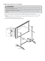
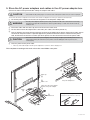
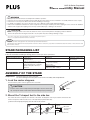
M-17/M-18/N-20/C-20 Series Copyboard Stand Assembly Manual This is the stand assembly manual for the M-17/M-18 and N-20/C-20 Series Copyboard. The copyboard is referred to as "the set" or "the main unit" below. WARNING • • • • • Only specially trained technicians should perform installation operations. Please be sure to perform the installation and assembly based on this manual. Incorrect installation or assembly will be the cause of injury. Please have 2 or more persons lift the main unit when installing or removing it. For details on installation, also refer to the main unit’s “User’s Manual” and “Assembly and Setup Manual”. Remove the 4 stabilizers and unlock the caster stoppers before moving the stand.To prevent the toppling, be sure to remove the stabilizers and unlock the stoppers.The toppling of the unit may result in bodily injury or damage to the machine. CAUTION • When mounting the printer on the main unit, attach the * Velcro to prevent the printer from slipping out due to vibrations. Remove the printer when moving the main unit. If not, the printer may fall, resulting in damage or injury. * The Velcro is meant to prevent slipping, not to fasten the printer in place. * Velcro is a registered trademark of Velcro Industries. Note • Diagrams of printers that appear in this manual are representative illustrations. The illustration may differ from the actual printer. Check the owner's manual of your printer for information about the names of the connectors and their locations and use. STAND PACKAGING LIST Please open the carton and check the parts. In the rare event that something is missing, please contact your store of purchase. Name T-shape legs (with casters) : 2 Horizontal bars:1 Assembly parts Screw caps: 2 Locking knobs 2 Cable cover: Mounted on stand Mount screws (M5 x 20 mm):2 (temporarily fastened on side bar) Mount screws (M5 x 40 mm ): 2 Sleeves: 2 Name Assembly parts Hexagonal socket screws (M5 x 8mm):8 Stabilizers:4 Printer table/AC power adapter box: 1 set (mounted on side bar) Velcro: 2 sets Hexagonal wrench (width across flats: 3 mm): 1 ASSEMBLY OF THE STAND Preparation: Mount the pen tray on the main unit. For the mounting instruction, please refer to the “Assembly and Setup Manual”. 1. Lock the caster stoppers. Press the bottom portion of the stoppers down to lock them. CAUTION Caster • Lock the casters of the T-shaped feet (left and right). If not, the stand could slip, causing the stand or main unit to fall and resulting in injury or damage. 2. Mount the T-shaped feet to the side bar. The shorter side of the T-shaped foot is the back of the stand. The diagrams show the procedure from the back side. Set the T-shaped foot with the cable cover on the right side (the printer table side). Remove the temporary fixing tape from the ends of the side bar. 1 Side bar M5 screw (mounted on side bar) Temporary fixing tape Temporary fixing tape Space of about 2 mm Insert the side bar's screw head into the T-shaped foot's screw hole (on the top), slide downwards, then use the hexagonal wrench to partially fasten. Insert the M5 x 40 screw into the sleeve, then use the hexagonal wrench to partially fasten it to the side bar. • Check that the sleeve is not sticking out. • Once mounting of the left and right T-shaped feet is completed, tighten the four screws, adjusting so there is no looseness. Fasten the screw caps to the screw heads of the left and right T-shaped feet. A: With the screw caps set slightly at an angle, place the hooks into the screw holes in the T-shaped feet and slide downwards. B: Press the stoppers of the screw caps into the hollows in the M5 screw heads. 2 Hexagonal wrench 3 4 Sleeve Side bar * The diagram used for explanation here is see-through. Screw hole A. Hook Screw cap Hexagonal wrench B. Stopper M5 x 40 mm screw M5 screw head Cable cover Printer table Side bar Front (long) Back (short) 3. Attach the stabilizers to the front and back of the T-shaped feet. CAUTION • To prevent toppling, be sure to install the stabilizers at each of the 4 locations. The toppling of this machine could cause bodily injury or damage the machine. Alignment of the screw holes of the T-shape feet with those of the stabilizers. Slide the stabilizers on the T-shaped feet to align with the holes. T-shape foot CAUTION • Do not lift the stand to work on it. This may lead to toppling or bodily injury. Stabilizer Secure the stabilizers on the T-shape feet by hexagonal screws using hexagonal wrench. Hexagonal socket screws (M5 x 8mm) Attach the 4 stabilizers on the feet. Hexagonal wrench 4. Mount the main unit on the stand. CAUTION • To prevent accidental injury due to the main unit dropping or tipping over, the main unit should be held by at least two persons when mounting it on the stand. • Check that the stand's hooks are securely inserted into the main unit's mounting holes. If not, the main unit could drop, resulting in injury and damaging the equipment. • Make sure the locking knobs are tightened when moving. If not, the side bar's mounts could be bent or otherwise damaged. The shorter side of the T-shaped foot is the back of the stand. The diagrams show the procedure from the back side. Place the stand's hooks in the mounting holes in the main unit's support pieces and insert securely in the hook grooves. Holes are located in three positions. The mounted height can be adjusted in three steps of 100 mm (1747, 1847 or 1947 mm (maximum height)) according to which set of holes is used. Fasten the main unit with the locking knobs (left and right). The rear frame Mounting hole 1 Hook 2 Locking knobs Front (long) Back (short) 5. Store the AC power adapters and cables in the AC power adapter box. Connect the main unit and printer before storing the adapters and cables. • Check that the AC power plug is not connected to a wall power outlet. If it is, be sure to unplug it. CAUTION The shorter side of the T-shaped foot is the back of the stand. The diagrams show the procedure from the back side. Put the AC power adapters of the main unit and printer in the AC power adapter box. • The AC power adapters and the power cords generate heat. Be sure to wire them in such a way that they keep apart. Do not bundle the cables together. Doing so could cause them to heat up, leading to fire. WARNING Fasten the cables with the cable clip, then insert them in the cable cover. Put the cables into the AC adapter box's cable hole. (The cables enter when pushed in.) Peel the backing sheet of the Velcro and attach the Velcro to the bottom of the printer and the printer table. Fasten the Velcro on the printer table in a position opposite the position on which the Velcro is attached on the printer. Also, do not attach the Velcro to a sunken part of the printer, or it will not touch the Velcro on the printer table. • The Velcro is attached to prevent slipping. It is not strong enough to prevent falling. Remove the printer when moving the stand. If not, the printer could be damaged or fall on your feet, etc., causing injury. CAUTION Place the printer on the printer table. • Place any extra cable length in the AC power adapter box so that no cable is hanging out. This completes mounting of the main unit on the stand. Make a test print. ce a urf rs a Re ུ Cable clip ཱ ce r ea a urf ཱ s AC power adapter box Cable cover R Main unit's AC power adapter Printer's AC power adapter Velcro ཱི ཱི ི Using the cable clip Cable hole Fasten the cables with the cable clip. Velcro 26-4626-11D