1
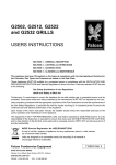
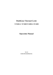
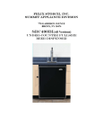
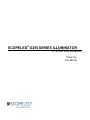
SCOPELED® G250 SERIES ILLUMINATOR
OPERATION MANUAL
Table Top
Pole Mount
COPYRIGHT © 2015-2016 ScopeLED®
All rights reserved. Printed in the United States of America.
This manual may not be reproduced in whole or in part, in any form or by any means, without the express written
permission of ScopeLED® .
NO LIABILITY FOR ERRORS
ScopeLED® reserves the right to correct technical and typographical errors in this manual at any time, without prior notice.
In no event shall ScopeLED® be liable for errors in this manual or for any damages arising out of or relating to this manual.
PRODUCT WARRANTY/LIMITATION OF REMEDITS
ScopeLED® warrants, to the original Buyer, all of its products to be free from defects in both workmanship and material for
a period of one year from the date of shipment. This warranty extends to all products, which have proved defective
through normal use, but excludes products that have been damaged, mishandled, disassembled, modified, or misused by
Buyer or any other person. This warranty is in lieu of all other warranties, and ScopeLED ® disclaims all other warranties
express or implied, including any warranty of merchantability, fitness for a particular purpose, or arising from the course of
dealing between the parties or usage of trade. ScopeLED® does not extend any warranty of any kind whatsoever to any
purchaser of the products from Buyer or to any end-user of the products. ScopeLED® , at its sole choosing, will replace or
repair to proper working condition any products under warranty that are returned. Products repaired or replaced under
warranty are only warranted for the remaining unexpired period of time of the original warranty. ScopeLED ® reserves the
right to issue a credit memo for any defective product as an alternative to product replacement or repair. ScopeLED® will
not accept Buyer generated debit memos. Buyer may not set off or withhold payment because any product is defective. In
no event shall ScopeLED® liability under this warranty and this contract exceed the purchase price of the products. In no
event shall ScopeLED® be liable under this warranty or this contract for consequential, incidental or special damages.
RETURN MATERIAL AUTHORIZATION TERMS
ScopeLED will only accept a return of products for which a ScopeLED® Return Material Authorization ("RMA") Number
has been issued to Buyer prior to the shipment of the return products to ScopeLED ® . This RMA Number must be
displayed on all return shipment documents. ScopeLED® will refuse all returns that are not accompanied by an RMA
Number. All risks of any such refused shipment are the sole responsibility of Buyer.
For warranty returns, ScopeLED® will only accept return products accompanied by a statement of defects. ScopeLED ®
will not evaluate returns not including this information, and such returns will be returned to Buyer at Buyer's expense.
Warranty returns proved defective through damage, mishandling, disassembly, modification, or misuse by Buyer or any
other person, and warranty returns found non-defective, will be subject to evaluation and processing fees, and repair
costs if applicable. Non-warranty returns will be evaluated and will be subject to evaluation and processing fees. If nonwarranty repair work is necessary, Buyer will be notified of repair costs before a repair work order is initiated. Confirming
POs are required for non-warranty repair work.
For warranty returns, Buyer is responsible for one-way freight costs to ScopeLED® , including any duty and taxes.
ScopeLED® will cover freight costs for return shipment to Buyer. Shipment charges billed to ScopeLED® without prior
approval from ScopeLED® will be re-invoiced to Buyer.
For non-warranty returns, Buyer is responsible for two-way freight costs, including any duty and taxes. If shipment
consists of returns that are both warranty and non-warranty, the shipment will be considered as non-warranty.
ScopeLED® will not accept Buyer generated debit memos.
All international return shipments to ScopeLED® , including packaging and airway bill, must be marked "Goods made in
the United States; enter as American Goods Returned ('AGR')" and state the reason for the return to the United States.
ScopeLED® will refuse all returns that are not properly documented. All risks of any such refused shipment are the sole
responsibility of Buyer.
International returns should be sent via Federal Express, UPS or DHL. International returns may be processed using
ScopeLED® ’s brokerage: EWI Inc. 305 Harbor Way, South San Francisco, CA 94080. Contact David Li at TEL: (650) 7941388, FAX: (650) 794-1389. If one of these carriers or ScopeLED® ’s broker is not used, ScopeLED® may invoice Buyer
for any additional costs including duty and taxes.
REVERSE ENGINEERING/CONFIDENTIALITY
Buyer shall not reverse engineer, decompile, disassemble, modify, reproduce or copy any products or any software within
any products. Buyer shall not analyze or identify the chemical composition or the physical characteristics of any products.
Buyer shall not furnish ScopeLED® specifications to any other person.
SOFTWARE LICENSE
ScopeLED® does not transfer ownership of software contained in any products. ScopeLED ® grants to Buyer a perpetual
non-exclusive license to use software in the operation of the product in which it is contained. This license is transferable
only with the transfer of ownership of the product.
SCOPELED® G250 SERIES ILLUMINATOR
TABLE OF CONTENTS
PRODUCT OVERVIEW ........................................................................................ 1
ScopeLED® G250 Series Illuminator Overview ....................................................... 1
ScopeLED® G-Series Family Product Feature Matrix ............................................. 1
Models & Naming Convention .................................................................................. 2
Included Hardware & Accessories ........................................................................... 3
Safety Instruction ...................................................................................................... 4
HARDWARE SETUP ............................................................................................ 5
Table Top Model Installation .................................................................................... 5
Pole Mount Model Installation .................................................................................. 7
Installation Recommendations ............................................................................... 11
MANUAL OPERATION ...................................................................................... 12
Control Panel ........................................................................................................... 12
Basic Operation ....................................................................................................... 13
TROUBLE SHOOTING ...................................................................................... 14
SPECIFICATIONS .............................................................................................. 15
Absolute Maximum Ratings.................................................................................... 15
Optical Specifications ............................................................................................. 15
Mechanical Dimensions .......................................................................................... 15
Mechanical Drawings .............................................................................................. 16
SCOPELED® G250 SERIES ILLUMINATOR
PRODUCT OVERVIEW
This product must be installed in accordance with the applicable installation code by a
person familiar with the construction and operation of the product and hazards involved.
ScopeLED® G250 Series Illuminator Overview
ScopeLED® G250 Series offers high brightness, single color and adjustable intensity in a
compact, flexible, and convenient package. Different colored LED chips packed into DiCon’s
Dense Matrix LED™ Array couple light efficiently into a light guide, illuminating your sample with
selectable colors to enhance contrast, protect wavelength sensitive samples, and optimize
viewing comfort.
The LEDs do not emit in the UV and IR spectral regions, eliminating the need for special filters.
Undesirable light and sample interactions such as photobleaching in fluorescence and
unintended curing in photosensitive adhesives can be avoided by selecting a color channel that
doesn’t interact with the sample.
The G250 Series combine optical power, flexibility, and usability in a compact form and is a great
choice for your application.
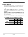
ScopeLED® G-Series Family Product Feature Matrix
Features
Mounting
Controls
Type
Table Top
Pole Mount
Manual Control
USB Control
Tunable White
LED Color
RGB
Single Color
ScopeLED® G-Series
G150
G180
G250
x
x
x
x
x
x
x
x
x
x
x
x
(3 modes)
(6 modes)
x
x
x
x
SCOPELED®
Copyright2015©
Page 1 of 17
Product Overview
SCOPELED® G250 SERIES ILLUMINATOR
Models & Naming Convention
The ScopeLED® G250 Series has two different mounting types:
Table Top
Pole Mount
Both the Table Top and Pole Mount illuminators come in single color output types of 3000K,
4300K, 5600K and 6500K.
Please reference the label at the bottom of the unit to confirm that you are using one of these
models. If not, contact the manufacturer for the proper user manual.
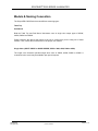
Single Color (G250T-XXXXK or G250P-XXXXK, XXXX = 3000, 4300, 5600 or 6500)
The single color illuminator provides single white color at 3000K, 4300K, 5600K or 6500K. A
customized color model may be available upon special request.
SCOPELED®
Copyright2015©
Page 2 of 17
Product Overview
SCOPELED® G250 SERIES ILLUMINATOR
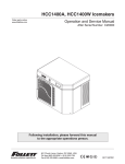
Naming Convention for ScopeLED® G Series family product
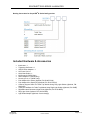
Included Hardware & Accessories
Illuminator x 1
Tightening Set Screw x 1
AC/DC Power Adapter x 1
AC Power Cord x 1
Quick Start Guide x 1
M3 Screw x4 (G250P Only)
Stand Adapter x1 (G250P Only)
Mounting Knob x1 (G250P Only)
Pole Adapter 40 to 32mm (Optional, PN: SLAG-PA32)
Pole Adapter 40 to Specify ID (Optional, PN: SLAG-PACU)
G-Series Support Stand for Table Top Models Using Ring Light Guides (Optional, PN:
SLAG-SS)
G-Series Lead Base for Table Top Models Using Rigid Light Guides (Optional, PN: BASE)
Rigid Bifurcated Gooseneck Light Guide (Optional, PN: SLAG-BIFR)
Ring Light Guide (Optional, PN: SLAG-RING)
Light Guide Adapter (Optional, Custom design)
SCOPELED®
Copyright2015©
Page 3 of 17
Product Overview
SCOPELED® G250 SERIES ILLUMINATOR
Safety Instruction
Warnings
Never look directly at the light output port.
Inappropriate usage of ScopeLED® G-Series products could result in eye damage.
Installation of the product onto readily available microscopes should always be performed
according to the written guidelines.
Attention (also see Installation Recommendations & Absolute Maximum Ratings)
The statements regarding safety of operation of the G-Series will apply only when the
product is operated correctly.
Any installation or attachment of light guide to the G-Series Illuminator should always be
performed with power adapter and other cables disconnected.
When installing or removing a light guide, the G-Series Illuminator ON/OFF switch should
always be set to OFF.
The G-Series must not be operated in explosion prone environments. The G-Series
products must always be operated with shielded cables.
SCOPELED®
Copyright2015©
Page 4 of 17
Product Overview
SCOPELED® G250 SERIES ILLUMINATOR
HARDWARE SETUP
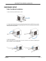
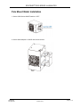
Table Top Model Installation
1. Set the G250 Series ON/OFF switch to “OFF”
2. If using a rigid self-supporting single or bifurcated light guide with the G250T table top models,
the auxiliary stand will support the extended light guide. Pull out both stands and extend them
until they reach the end position.
3. Light Guide Installation
Insert a light guide into the Light Output Port until it meets the end. Rotate the Tightening Set
Screw clockwise to secure the light guide.
SCOPELED®
Copyright2015©
Page 5 of 17
Hardware setup
SCOPELED® G250 SERIES ILLUMINATOR
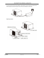
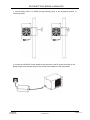
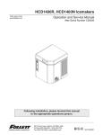
4. Connect the 24V AC/DC Power Adapter to the illuminator at the DC power port shown on the
model images below and then plug the 24V AC/DC Power Adapter to wall socket
Table Top Controls
SCOPELED®
Copyright2015©
Page 6 of 17
Hardware setup
SCOPELED® G250 SERIES ILLUMINATOR
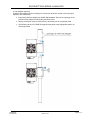
Pole Mount Model Installation
1. Set the G250 Series ON/OFF switch to “OFF”
2. Secure Stand Adapter on G250P with four M3 screws.
SCOPELED®
Copyright2015©
Page 7 of 17
Hardware setup
SCOPELED® G250 SERIES ILLUMINATOR
3. Use Mounting Knob to fix G250P through Mounting Hole at the appropriate position on
microscope stand.
4. Connect the 24V AC/DC Power Adapter to the illuminator at the DC power port shown on the
Model images below and then plug the 24V AC/DC Power Adapter to wall socket stand.
SCOPELED®
Copyright2015©
Page 8 of 17
Hardware setup
SCOPELED® G250 SERIES ILLUMINATOR
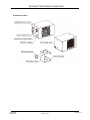
4. Pole Adapter (optional)
SLAG-PA Pole Adapter will be necessary for microscope stand with vertical or horizontal pole
diameters less than 40mm.
Insert SLAG-PA Pole Adapter into G250P Stand Adapter. Be sure the openings on the
SLAG-PA Pole Adapter are facing the post thumbscrew
Slip the set with the insert over the vertical or horizontal pole of microscope stand.
Use Mounting Knob to fix G250P through Mounting Hole at the appropriate position on
microscope stand.
SCOPELED®
Copyright2015©
Page 9 of 17
Hardware setup
SCOPELED® G250 SERIES ILLUMINATOR
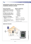
Pole Mount Controls
SCOPELED®
Copyright2015©
Page 10 of 17
Hardware setup
SCOPELED® G250 SERIES ILLUMINATOR
Installation Recommendations
Mounting
The G250 Series Illuminator is available as a Table Top unit, or as a Pole Mount unit that is
intended for mounting on typical microscope stands from 32mm to 40mm in diameter. The
following considerations should be made before choosing a mounting option.
Environment
The illuminator is not suited for wet or damp locations. Be sure to protect all electronics from
moisture.
Do not mount or locate the unit in an explosive environment near combustible material.
Air Volume
Do not encase or bury the unit in any way that restricts airflow.
Orientation
The post-mount version can be oriented vertically, horizontally, or inverted. Be sure that the
mounting method and location is capable of supporting the weight of the illuminator.
Power Adapter
The output connector of the power adapter must be a female barrel connector for direct
compatibility with the G250 Series Illuminator.
Though the fitting between the output connector of the power adapter and input connector of the
Microscope Illuminator may be snug, the connection will not be able to support the weight of the
Illuminator. Do not use the power adapter as its own hanging device.
Light Guides
The G250 Series Illuminator is most efficient for light guides in the range of 4 to 25.4 mm outer
diameter. The Microscope Illuminator is designed to accept a variety of light guides. Custom size
adapters can be made upon request.
SCOPELED®
Copyright2015©
Page 11 of 17
Hardware setup
SCOPELED® G250 SERIES ILLUMINATOR
MANUAL OPERATION
Control Panel
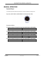
To manually operate the G250 Series Illuminator, one knob is available for intensity levels.
Single Color (G250T-XXXXK or G250P-XXXXK, XX = 3000, 4300, 5600 or 6500)
Preprogrammed Modes
Preprogrammed Modes for Single Color Output Type (G250T-3000K or G250P-3000K)
Mode
White Light CCT Value
1
3000K
Preprogrammed Modes for Single Color Output Type (G250T-4300K or G250P-4300K)
Mode
White Light CCT Value
1
4300K
Preprogrammed Modes for Single Color Output Type (G250T-5600K or G250P-5600K)
Mode
White Light CCT Value
1
5600K
Preprogrammed Modes for Single Color Output Type (G250T-6500K or G250P-6500K)
Mode
White Light CCT Value
1
6500K
SCOPELED®
Copyright2015©
Page 12 of 17
Manual Operation
SCOPELED® G250 SERIES ILLUMINATOR
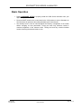
Basic Operation
1.
Follow HARDWARE SETUP to properly install the G250 Series Illuminator onto your
application system.
2.
Press the ON/FF switch on the control panel to the “ON” position to turn the illuminator on.
The illuminator will operate at the setting indicated by the control knobs.
3.
The Intensity knob is used to manually adjust the intensity or brightness of the modes
without changing its color parameters. Turning the knob fully clockwise results in
maximum brightness of the selected mode. Turning the knob fully counter-clockwise
results in dimming the selected mode to zero.
SCOPELED®
Copyright2015©
Page 13 of 17
Manual Operation
SCOPELED® G250 SERIES ILLUMINATOR
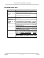
TROUBLE SHOOTING
Problem
Illuminator
turn on
Solution
does
not
Check that the green light on the power adapter is on and
verify that all of the connections to the adapter and the
Microscope Illuminator are properly connected.
Turn the intensity knob to maximum intensity
Light
output
appears red
only
Fan does not turn on
Illuminator
emitting
is
not
Illuminator is flickering
Illuminator has
down and is hot
shut
Make sure that the protective dust cover on the end cap has
been removed.
The fan should be on constantly. If the fan fails to engage, turn
off the unit immediately and contact the manufacturer.
Turn the intensity knob to maximum intensity. If any of the
colors appear unusually dim, please contact the manufacturer.
Flickering is often a result of the driver not receiving a high
enough DC voltage. Verify that the 12V DC output from the
power adapter is correct.
Shorten the line from the power adapter to the Microscope
Illuminator. Never exceed more than a 15 ft length from the
power adapter.
Power cycle the Microscope Illuminator by shutting off the
power to the power adapter and restarting.
Check to make sure the fan is operating properly and the
device is being used within its environmental temperature
range (see Installation Recommendations & Absolute
Maximum Ratings)).
Make sure there is nothing obstructing the airflow to the
Microscope Illuminator. It is required that a minimum of eight
cubic feet of airspace is provided around the device.
SCOPELED®
Copyright2015©
Page 14 of 17
Trouble Shooting
SCOPELED® G250 SERIES ILLUMINATOR
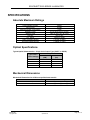
SPECIFICATIONS
Absolute Maximum Ratings
Power Adapter Voltage
Input Current
Maximum Power Consumption
Operating Temp
Storage Temp
Humidity
CCT Range
Table Top Model Weight
Pole Mount Model Weight
24VDC
5A Max
110W
0ºC to 40ºC (32ºF to 104ºC)
-20ºC to 75ºC (-4ºF to 167ºF)
10% to 90%
3000K to 6500K
1.471KG (3.24lbs)
1.239KG (2.73lbs)
Optical Specifications
Typical Optical Characteristics – Single Color Output Type (G250T or G250P)
Typical CCT /
Color Settings
3000K
4300K
5600K
6500K
8mm Light Guide
Radiant Flux Luminous Flux
(mW)
(Lm)
1950
550
2300
700
2350
750
2350
750
Mechanical Dimensions
Mechanical Dimensions for all Microscope Illuminator models
Model
Dimensions (Illuminator only, unit in mm)
Table Top
177 (L) x 155 (W) x 93 (H)
Pole Mount
171 (L) x 111 (W) x 93 (H)
SCOPELED®
Copyright2015©
Page 15 of 17
Specifications
SCOPELED® G250 SERIES ILLUMINATOR
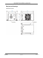
Mechanical Drawings
G250 Table Top Series
SCOPELED®
Copyright2015©
Page 16 of 17
Specifications
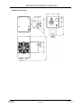
SCOPELED® G250 SERIES ILLUMINATOR
G250 Pole Mount Series
SCOPELED®
Copyright2015©
Page 17 of 17
Specifications