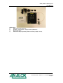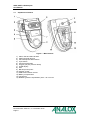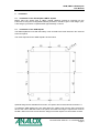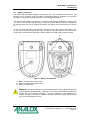
1
ADM, HBOT & Sub Aspida
User Manual
Analox Ltd.
15 Ellerbeck Court, Stokesley Business Park
North Yorkshire, TS9 5PT, UK
T: +44 (0)1642 711400
W: www.analox.net
F: +44 (0)1642 713900
E: [email protected]
ADM, HBOT & Sub Aspida
User Manual
List of Contents
1
2
3
4
5
6
7
8
Safety information ...............................................................................................................3
Package contents checklist .................................................................................................4
Aspida devices overview .....................................................................................................6
3.1
Aspida main features ...................................................................................................8
Installation ...........................................................................................................................9
4.1
Installation of the Sub Aspida & HBOT Aspida ............................................................9
4.1
Installation of the ADM Aspida .....................................................................................9
4.2
Gaining access to the ADM Aspida ...........................................................................10
4.3
Battery installation ......................................................................................................11
4.4
Charging the Analox Aspida.......................................................................................12
Operation...........................................................................................................................13
5.1
Button functions .........................................................................................................13
5.2
Switching the device on/off ........................................................................................13
5.3
User registration .........................................................................................................13
5.4
The main display ........................................................................................................14
5.5
Screen saver ..............................................................................................................14
5.6
Battery status .............................................................................................................15
5.7
Menus.........................................................................................................................15
5.8
Common menu items .................................................................................................16
5.9
Gas alarms .................................................................................................................17
5.10
Global alarm options...............................................................................................18
5.11
Alarm latching .........................................................................................................18
5.12
Alarm muting ..........................................................................................................18
5.13
Quiet alarms ...........................................................................................................18
5.14
Data logging ...........................................................................................................19
5.15
Man-down alarm .....................................................................................................19
5.16
Panic alarm.............................................................................................................20
5.17
Time-weighted average (TWA) monitoring of carbon dioxide ................................20
5.18
Maintenance reminders ..........................................................................................21
5.19
Calibration reminders .............................................................................................21
5.20
Sensor replacement reminders ..............................................................................21
5.21
Faults ......................................................................................................................22
5.22
Troubleshooting......................................................................................................22
Maintenance ......................................................................................................................23
6.1
Spares & accessories ................................................................................................23
6.2
Calibration ..................................................................................................................24
6.3
Sensor calibration ......................................................................................................24
6.4
Oxygen sensor replacement ......................................................................................26
6.5
Cleaning .....................................................................................................................33
Specifications ....................................................................................................................34
Disposal.............................................................................................................................36
8.1
WEEE statement........................................................................................................36
8.2
Oxygen sensor disposal.............................................................................................36
Document Ref: PSA-811-10 - November 2012
Page 1
ADM, HBOT & Sub Aspida
User Manual
Document Ref: PSA-811-10 - November 2012
Page 2
ADM, HBOT & Sub Aspida
User Manual
1
Safety information
WARNING: Read the safety information fully before using the aspida.
WARNING: Do NOT attempt to charge the batteries while the device is inside the
hyperbaric chamber.
High volume audible alarm
The Aspida employs high volume warning alarms with a sound pressure level at 1m of 95dB
in the case of normal gas alarms, and up to 110dB in the case of the man-down alarm.
As the man down sounder is disabled by default when supplied but may be user enabled,
care should be taken to minimise exposure to the sounder. The aspida unit should always be
worn away from the head in order to minimise close range exposure to the alarm.
WARNING: The 110dB man-down alarm can, when enabled, be manually activated
at any time by holding the
button if the panic alarm is configured to be available.
Care should be taken not to activate this alarm when the Aspida unit is in close
proximity to the ears.
WARNING: Do NOT exceed 2 bar/min atmospheric pressure change when using the
HBOT Aspida.
Electrochemical oxygen sensor
The oxygen sensor used in the Aspida is an electrochemical sensor which contains
potassium hydroxide. Under normal conditions the sensor is sealed. To prevent leakage, the
unit must not be exposed to temperatures outside the specified range, or be exposed to
organic vapours, which may cause physical damage to the body of the sensor. The unit must
not be stored in areas containing organic solvents or in flammable liquid stores.
Document Ref: PSA-811-10 - November 2012
Page 3
ADM, HBOT & Sub Aspida
User Manual
2
Package contents checklist
Sub Aspida
a)
Analox Aspida main unit
b)
2xAA rechargeable batteries
c)
Wall mounting plate (Including fixing kit) or belt-clip attachment (only one supplied)
d)
Charger power supply to suit
e)
USB communication cable
f)
Software disc
g)
Quick start guide
h)
Calibration adaptor
HBOT
a)
b)
c)
d)
e)
f)
g)
h)
i)
Aspida
Analox Aspida main unit
2xAA rechargeable batteries
Wall mounting plate (Including fixing kit)
Charger power supply to suit
USB communication cable
Software disc
Quick start guide
Calibration adaptor
Test certificate
Document Ref: PSA-811-10 - November 2012
Page 4
ADM, HBOT & Sub Aspida
User Manual
ADM Aspida
a)
ADM panel mount main unit
b)
Universal charger/power supply (Including adaptors)
c)
Quick start guide
d)
Calibration adaptor (Including 300mm of tubing, single or dual)
Document Ref: PSA-811-10 - November 2012
Page 5
ADM, HBOT & Sub Aspida
User Manual
3
Aspida devices overview
The Analox Aspida is a purpose designed compact portable gas monitor capable of
continuous monitoring of both carbon dioxide (CO2) and oxygen (O2).
Each instrument in the Aspida family gives clear audible and visible warning of potentially
dangerous gas levels. A high resolution Organic Light-Emitting Diode (OLED) display shows
clear, live gas levels in all light conditions.
The Analox Aspida is housed in a robust, IP65 splash proof enclosure. The instrument
operates using rechargeable battery technology, allowing it to run for more than 12 hours
continuously between charges. An Analox Aspida allows for easy replacement of the
rechargeable batteries with standard, AA, non-rechargeable batteries in circumstances where
recharging is not possible.
Sub Aspida overview
The inclusion of a pressure sensor in the Sub Aspida provides accurate, pressure
compensated O2 and CO2 readings across 800 to 1200mbar pressure.
The inclusion of a belt clip attachment allows for secure and comfortable attachment of the
Sub Aspida to clothing for portable, personal protection.
Sub Aspida factory default settings
Parameter
Setting
O2 Alarms
%Vol Version
18%
19.5%
23%
CO2 Alarms
%Vol Version
0.5%
1.5%
4%
0.5% TWA Alarm
Alarm Latch State
Non-latching
Alarm Muting State
Mutable
Man-down State
Disabled
Logging Rate
30 seconds
Document Ref: PSA-811-10 - November 2012
Page 6
mbar ppO2 versions
180 mbar ppO2
195 mbar ppO2
230 mbar ppO2
mbar ppCO2 versions
5 mbar ppCO2
15 mbar ppCO2
40 mbar ppCO2
5 mbar ppCO2 TWA Alarm
ADM, HBOT & Sub Aspida
User Manual
HBOT Aspida overview
Reinforcement of the unit allows for the HBOT Aspida to provide accurate, pressure
compensated O2 and CO2 readings across an extended pressure range of 800 to 3000 mbar
absolute.
HBOT Aspida factory default settings
Parameter
Setting
O2 Alarms
%Vol
18%
19.5%
23%
CO2 Alarms
%SEV
0.5%
1.5%
4%
Alarm Latch State
Alarm Muting State
Man-down State
Logging Rate
Non-latching
Mutable
Disabled
30 seconds
ADM Aspida overview
The ADM Aspida is a static panel system that offers continuous monitoring of O2, CO2 or dual
gas.
ADM Aspida factory default settings
Parameter
Setting
O2 Alarms
%Vol Version
18%
19.5%
23%
CO2 Alarms
%Vol Version
0.5%
1.5%
4%
Alarm Latch State
Alarm Muting State
Man-down State
Logging Rate
Non-latching
Mutable
Disabled
30 seconds
Document Ref: PSA-811-10 - November 2012
Page 7
ADM, HBOT & Sub Aspida
User Manual
3.1
Aspida main features
Figure 1 - Main features
1)
2)
3)
4)
5)
6)
7)
8)
9)
10)
11)
12)
13)
14)
Alarm, fault and OK indicators
Carbon dioxide gas port
Cancel/exit/panic-alarm button
Cycle button
Confirm/on/off button
Oxygen gas port (if sensor fitted)
OLED display
Horn
Belt loop mount point
Charger socket
USB communication socket
Battery compartments
Lanyard pin
Breather (pressure equalisation) hole – do not cover
Document Ref: PSA-811-10 - November 2012
Page 8
ADM, HBOT & Sub Aspida
User Manual
4
Installation
4.1
Installation of the Sub Aspida & HBOT Aspida
Before using the Analox Sub or HBOT Aspida, batteries should be inserted into the
instrument. If using the rechargeable batteries provided, it should be given a full charge cycle.
A full charge cycle will be complete within approximately 4.5 hours.
4.1
Installation of the ADM Aspida
The ADM Aspida will come with the battery cover secured to the main unit and in turn secured
to the front panel.
The cutout required for the ADM Aspida is shown below.
Optional fixing kits are available from Analox, see spares and accessories list at section 6.1
To install the ADM Aspida into your panel place the captive nuts from the fixing kit through
each of the 10mm diameter holes in the panel, then while securing the captive nuts screw in
the M5 x 25mm Pozi Pan screws from the fixing kit until the captive nut comes back on itself.
Document Ref: PSA-811-10 - November 2012
Page 9
ADM, HBOT & Sub Aspida
User Manual
Make sure that the pipework supplied with the ADM Aspida has been connected to your gas
line and the supplied 9V PSU’s DC jack is connected to the rear of the unit.
Remove the screws and align the ADM Aspida front panel mounting holes up with the captive
nuts, then re-insert the M5 x 25mm Pozi Pan screws through and tighten.
The diagram below shows the exploded view of the ADM installation.
4.2
Gaining access to the ADM Aspida
To gain access to the ADM Aspida for either USB connection or sensor change the following
steps should be followed.
Firstly remove the ADM Aspida from the instrument panel by removing the four M5 x 25mm
Pozi Pan screws.
Turning the ADM Aspida over, remove the two left most screws and washers from the tie
bases.
You should now be able to remove the Aspida main unit from the panel and be able to
remove the battery cover as described in section 4.3
Document Ref: PSA-811-10 - November 2012
Page 10
ADM, HBOT & Sub Aspida
User Manual
4.3
Battery installation
The Analox Sub and HBOT Aspida’s are powered by a pair of standard AA batteries. The
devices can be powered using the NiMH re-chargeable batteries included in the product
package or using a pair of standard alkaline, non-rechargeable batteries.
The Analox ADM Aspida is powered by a universal mains adaptor, 90-264VAC to 9VDC, with
a 2.1mm x 5.5mm x 12mm DC jack plug – centre pin positive. Battery backup is available as
an optional extra, this can be supplied by Analox, see spares and accessories list at section
6.1
To gain access to the battery compartment, undo the screw in the centre of the battery cover
on the rear of the device and lift the cover off. Before removing batteries from the device,
ensure that it is switched off and that the mains charger and USB cable are disconnected.
Figure 2 - Battery compartment
1) Battery compartment access screw
2) Sensor compartment access screws
3) Battery compartments
WARNING: Care should be taken when inserting batteries, paying particular attention
to the orientation of each battery. Markings on the inside of the battery compartment
indicate the correct battery orientation. Incorrect orientation of the batteries may
result in damage to the device. Batteries should be inserted by hand without use of
tools using reasonable force only.
Document Ref: PSA-811-10 - November 2012
Page 11
ADM, HBOT & Sub Aspida
User Manual
4.4
Charging the Analox Aspida
WARNING: The following safety warnings should be observed before attempting to
charge the Analox Aspida:
The Analox Aspida should only be charged when the NiMH batteries supplied with
the product are fitted. Attempting to recharge non-rechargeable alkaline batteries will
in most cases result in an aborted charge, and this will be indicated by a flashing
icon on the display. However, connecting the mains charger whilst using
alkaline batteries is not recommended and may result in damage to the device.
The Analox Aspida may be used with standard rechargeable AA batteries which have
been charged using a third-party charging device. However, only NiMH batteries
provided by Analox should be used when attempting to charge batteries within the
device using the mains charger.
Do NOT attempt to charge the batteries in the HBOT Aspida while the device is
inside the hyperbaric chamber.
Do not attempt to charge the device using a mains charger other than the one
supplied with the device. Use of an incorrect mains charger may damage the device
and invalidate the warranty.
The battery cover should always be securely fitted before performing a charge.
•
•
•
With the mains charger disconnected from the wall outlet, insert the power jack into
the socket on the rear of the Aspida device.
Insert the mains charger into the wall outlet.
Switch on the mains at the wall outlet.
NOTE: The unit can be charged whilst switched on or switched off.
The following lists the conditions that may be observed during a charge.
Battery icon state
Audible warning
Charge status
>>
(animated)
None
Charging (charge setup)
>>
>>
None
Charging
>>
(animated)
None
Charging
(approx. 1.5 hours remain)
Success beep
Charge complete
Fault beep
Charge fault
Batteries not rechargeable
Fault beep
No batteries
(flashing)
(animated)
The normal charge period for a set of fully discharged batteries is approximately 4.5 hours.
WARNING: During charging, the device will warm up. This effect is normal. It is
however suggested that the device is charged indoors at room temperature to ensure
a full charge cycle completes.
Document Ref: PSA-811-10 - November 2012
Page 12
ADM, HBOT & Sub Aspida
User Manual
5
Operation
5.1
Button functions
The Analox Aspida has three buttons that are used as follows:
Button
Function
• Power on/off
• Confirm
• Select button
• Show device menu
• Cycle through options
•
•
5.2
Cancel
Return to main screen
Switching the device on/off
To switch the Analox Aspida on, press the
button.
After a few seconds, the main gas display screen will be shown. If multiple user-names are
registered to the device then the user-name selection screen will be shown instead. See the
section ‘User registration’ for further instructions.
On start-up, the sensors have a short warm-up period. Live gas values will not be displayed
until the sensors have completed their warm-up. Typically, for oxygen, the warm-up takes 15
seconds and for carbon dioxide, the warm-up takes 30 seconds. Sensor warm-up will be
shown on the display.
To switch off the device, from the main display press and hold the
goes blank then release the button.
button until the screen
To return to the main display from the menu system, press and release the
required to exit the menus
button as
NOTE: The device cannot be turned off when powered from USB.
5.3
User registration
The Analox Aspida allows for registration of up to two usernames. This allows users to share
use of the device. On start-up, a username is selected, and all subsequent gas information is
logged internally against the selected user ID. Users can be registered to a device using the
Aspida configuration software. See the Aspida configuration software for instructions.
On device power up, if a single user is registered, the username will be displayed for a few
seconds, after which the device will operate normally.
If 2 users are registered, both usernames will be displayed in a menu for the user to select.
Pressing the
button will cycle between highlighted usernames. The
the highlighted user.
button will select
NOTE: If a user is not selected within 2 minutes of start-up, a ‘no user’ ID will be selected
automatically and the device will proceed to run normally. During these two minutes, a
reminder beep will be sounded to prompt the user to select an ID.
Document Ref: PSA-811-10 - November 2012
Page 13
ADM, HBOT & Sub Aspida
User Manual
5.4
The main display
Under normal operation, gas values for each of the sensors fitted are shown in their own
window along with the description of the gas type and measurement units. The current gas
value for each sensor will be updated on the display once per second.
Figure 3 - Dual sensor display (left), single sensor display (right)
1)
2)
3)
4)
5)
Man-down detection enabled icon
Clock
Measured gas types (dual sensor)
Measured gas values (dual sensor)
Measured gas units (dual sensor)
6)
7)
8)
9)
10)
11)
Quiet mode enabled icon
5
Atmospheric pressure (mBar)
Battery status icon
Measured gas type (single sensor)
Measured gas value (single sensor)
Measured gas units (single sensor)
NOTE: The ADM Aspida does not include a pressure sensor, it has a fixed atmospheric
pressure reading of 1000 mbar. This value is displayed as above but will remain at 1000
mbar.
5.5
Screen saver
The screen saver function is intended to extend the battery life of an Aspida and reduce
screen burn-in. If the user does not operate any buttons for one minute then the screen saver,
when enabled, will automatically dim the display.
Pressing any button will wake the device from screen saver mode.
If the device is connected to the charger or connected to a PC via USB, the screensaver will
not be shown, but the display will still dim as normal.
During screen saver mode, gas values are still monitored as normal. Any gas alarm will wake
the display from screen saver immediately and the main gas display will be shown.
It is possible to enable/disable the screen saver option via the supplied PC software.
5
NOTE: For the ADM aspida the pressure reading is fixed at 1000 mbar.
Document Ref: PSA-811-10 - November 2012
Page 14
ADM, HBOT & Sub Aspida
User Manual
5.6
Battery status
The battery status icon is shown in the top right hand corner of the display. This icon gives a
representative indication of the power remaining in the batteries. As the batteries run down
from full to empty, the battery icon will be displayed in various states.
Icon
Battery status
Battery sufficiently charged
,
Battery low
(flashing)
Battery nearly empty. Approx. 1 hour of operation
remaining. A reminder beep will sound periodically.
The device is powered from the mains charger. The icon
will be shown next to the battery icon.
The device is attached to and powered by a computer via
a USB cable. The USB symbol will be shown instead of
the battery icon (in addition to, if charging).
NOTE: Due to the nature of the battery type, the battery status icon may temporarily indicate
a capacity higher than the true remaining battery capacity upon switch-on. This effect is
usually seen in devices which have been switched off for an extended period of time. The true
battery status will be indicated within a few minutes of power-up.
5.7
Menus
The device main menu can be accessed by pressing the
screen similar to the one shown below.
button. This will display a menu
Figure 4 - A typical menu
NOTE: The menu icons displayed will vary depending on the configuration of the device and
the sensor fitted.
Press
to cycle through the menu options and highlight the chosen option. If an arrow is
present at either end of the menu, it indicates that there are more options beyond the edges
of the visible menu. Advancing the menu cursor past the end of the visible menu will reveal
the extra menu items.
Pressing the
Pressing
button when the chosen option is highlighted will select that option.
at any time whilst the menu is shown will return to the main gas display.
Document Ref: PSA-811-10 - November 2012
Page 15
ADM, HBOT & Sub Aspida
User Manual
5.8
Common menu items
Menu Icon
Function
Information - Selecting this menu item will display a screen with
information related to the specific device, such as serial number and
firmware version.
Back - Selecting back exits the menu and returns to the main gas
display.
Carbon dioxide calibration - (carbon dioxide configurations only)
Select this option to perform a calibration of the carbon dioxide sensor.
This feature is described in further detail in the section 6.3.
Oxygen calibration - (oxygen configurations only) Select this option to
perform a calibration of the oxygen sensor. This feature is described in
further detail in the section 6.3.
Carbon dioxide sensor information - (carbon dioxide configurations
only). This option displays a page which gives information about when
the sensor is next due a calibration.
Oxygen sensor information - (oxygen configurations only). This option
displays a page which gives information about when the sensor is next
due a calibration and also when replacement of the sensor is due.
Document Ref: PSA-811-10 - November 2012
Page 16
ADM, HBOT & Sub Aspida
User Manual
5.9
Gas alarms
The Analox Aspida has a range of configurable alarms to warn the user of potentially
dangerous atmospheres. For each gas sensor fitted to the device, up to 3 configurable alarms
are available. In the case of carbon dioxide, an extra time weighted average (TWA) alarm is
provided. See section 5.17 for more details.
In the case of an alarm condition being detected, the horn will activate giving an audible
warning to the user. At the same time, the red alarm indicators will flash.
The device also has a vibrating alert to accompany gas alarms. When an alarm is triggered
the unit will vibrate (vibration limited to 10 seconds when man down detection is enabled).
The unit will not vibrate whilst connected to USB or the charger.
A gas alarm condition will also be shown on the display, giving a clear indication of the gas
that has triggered the alarm. In the case of an alarm, the gas warning symbol
will appear
below the gas reading which will be surrounded by a flashing border, as shown below.
Figure 5 - The main gas display showing that carbon dioxide levels have triggered an
alarm
Each alarm is configurable as either high-going or low-going. In the case of a high going
alarm, if the gas value exceeds the configurable set-point, the alarm will be activated. The 3
gas alarms are also ranked in order of priority, so that if a more dangerous level of gas is
detected, the user is notified.
Example
Two low going alarms are normally configured for detection of low oxygen levels.
•
•
Priority 1 alarm is configured as a low going alarm with a set-point of 18.0% or
180mBar.
Priority 2 alarm is configured as a low going alarm with a set-point of 19.5% or
195mBar.
If using this setup the detected level of oxygen falls below 19.5%, priority 2 alarm will be
activated. The red indicators, vibration and horn will all activate, pulsing at a moderate
rate, and a visual warning will be given on screen. The oxygen value will be highlighted
and the gas warning symbol
shown below the reading.
If the detected oxygen level falls further so that it is below 18.0%, priority 1 alarm will be
activated. This alarm is of a higher priority than the priority 2 alarm so the urgency of the
alarm will be increased. The indicators, vibration and horn will begin to pulse more rapidly
to indicate that the severity of the alarm has increased.
There is also normally a priority 3 alarm is configured as a high going oxygen alarm with a
set-point of 23.0% or 230mBar
Document Ref: PSA-811-10 - November 2012
Page 17
ADM, HBOT & Sub Aspida
User Manual
5.10 Global alarm options
There are three configurable options which affect all of the Analox Aspida's alarms. Muting,
latching and quiet options are set using the Aspida configuration software. See the Aspida
configuration software manual for instructions.
5.11 Alarm latching
Sometimes it is useful for a user to be alerted to a harmful gas level, even after the level of
gas has dropped to a safe level. The Analox Aspida can be configured to use latching alarms
so that alarms triggered by harmful gas levels will not be missed. The latching alarms option
can be enabled using the Aspida configuration software.
If the device is configured to use latching alarms then any alarm that is triggered will remain
active until it is acknowledged by pressing the
button.
Example
If a high-going alarm is activated by an increasing level of gas, the alarm will continue
to sound even after the gas level has dropped below the alarm set-point. The alarm
can be acknowledged by pressing the
below the set-point.
button when the gas reading has fallen
In the case of multiple alarms, the highest priority alarm that was triggered will be
latched. If the priority 1 alarm is latched and the gas level drops below the priority 1
set-point, pressing the
button will clear the priority 1 alarm, however, if the gas
level is still sufficient to trigger the priority 2 alarm, the device will continue to alarm at
a priority 2 level.
5.12 Alarm muting
Sometimes it is desirable to be able to mute the horn or stop the device vibrating when an
alarm is triggered. The Analox Aspida provides an option to allow alarms to be muted. The
mutable alarms option can be set using the Aspida configuration software.
If the alarm muting option is set on the device, any active alarm can be silenced by pressing
the
button whilst in an alarm state. Pressing
will deactivate the horn and the vibration.
The red indicators and the on-screen warning will continue to flash until the alarm condition is
cleared by safe levels of gas. In the case where a lower priority alarm has been muted and a
higher priority alarm is triggered, the alarms will be un-muted.
Example
If a priority 2 alarm is activated and muted and the detected gas level changes so as
to activate a priority 1 alarm, the horn and vibration will re-activate to warn the user of
the increased severity. A muted alarm will not be un-muted in the case where the
alarm level drops to a lower priority.
5.13 Quiet alarms
Sometimes it is desirable to suppress the audible indication when alarm is triggered. The
Analox Aspida provides an option to allow alarms to be silenced. The quiet alarms option can
be set using the Aspida configuration software. The display will indicate quiet mode with an
icon
in the status area.
Document Ref: PSA-811-10 - November 2012
Page 18
ADM, HBOT & Sub Aspida
User Manual
5.14 Data logging
The Analox Aspida has a built in data-logging facility which will automatically log gas readings
for all fitted sensors and pressure, whenever the device is active. Readings are logged to
internal memory at a rate configurable through the user software. The device is capable of
storing over 7 days of continuous data. All data is logged with a date and time stamp, and
where multiple users are registered with the device, each set of readings is logged against the
selected user ID.
The data-log can be downloaded from the device for analysis using the Aspida configuration
software. See the Aspida configuration software manual for instructions.
5.15 Man-down alarm
The Analox Aspida is equipped with a man-down alarm which is disabled by default. If the
man-down alarm feature is enabled the Aspida device will monitor any movement the device
is subject to. If the user who is wearing the alarm is somehow incapacitated, an alarm will be
sounded to alert others in the nearby area of the accident.
NOTE: By default, the feature is disabled. Enabling or disabling the alarm is performed using
the Aspida configuration software (see the section on alarm settings for further details).
If the man-down feature is enabled, the device will sound a low volume pre-warning alarm
after it detects no movement over a period of 4 minutes. The pre-warning alarm will sound for
a period of 1 minute, during which a simple shaking of the device or pressing the
button
will reset the alarm timer. If after this 1 minute period there has still been no movement
detected then the device will activate its ultra loud siren to warn others of the incident. Once
the high volume alarm has been activated, the alarm can only be cancelled by pressing the
button. During a man down alarm condition, following screen will be shown.
Figure 6 - Display shown when the man-down alarm is triggered
WARNING: Care must be taken whilst using the Aspida device with the man down
alarm enabled. If the device is detached from the user's person and left on a
stationary surface, the man-down condition will be triggered. This can lead to
unintentional activation of the very high volume siren. As this siren sounds in excess
of 100dB, this may be potentially harmful to hearing. To avoid nuisance alarms, the
device should be switched off when left unattended.
NOTE: The man-down high volume siren causes a large strain on the Aspida’s batteries and
as such, the expected operating period for the device is significantly reduced if the man-down
alert is frequently triggered or allowed to run for extended periods of time.
NOTE: Use in a moving vehicle may provide enough movement to defeat the man-down
detection
NOTE: Man-down is disabled if the instrument is connected to USB or charger.
Document Ref: PSA-811-10 - November 2012
Page 19
ADM, HBOT & Sub Aspida
User Manual
5.16 Panic alarm
In cases where a worker is in distress and still conscious, it is possible to activate the ultraloud siren manually. To activate the panic alarm, press and hold the
of 1 second.
button for a minimum
5.17 Time-weighted average (TWA) monitoring of carbon dioxide
Carbon dioxide is toxic to the human body as concentrations increase. Short term exposure to
the gas can be potentially lethal. Longer term exposure to more moderate levels of carbon
dioxide can also be detrimental to health, so health and safety bodies such as UK HSE define
occupational exposure levels (OEL) for the gas. These OELs provide a recommended safe
exposure to carbon dioxide whilst under working conditions. The occupational exposure levels
are based on a calculated time-weighted average (TWA) level of carbon dioxide in any one 24
hour period. The TWA calculation is based on average carbon dioxide levels weighted to an
assumed standard 8-hour daily working shift.
The Analox Aspida has a facility which automatically calculates a TWA value on a per-user
basis. When a user powers on the device and selects a user ID, the Analox Aspida begins
calculating and continuously updating that user’s own TWA. The device also takes into
account any historic data from the last 24 hours which is relevant to the selected user. TWA
data is logged alongside the actual gas readings in the internal data log.
NOTE: If no users IDs are registered to the device, the TWA values will all be attributed to a
default user.
An alarm feature is provided which will warn of a high TWA exposure to carbon dioxide. In
th
addition to the normal 3 available gas alarms per sensor, carbon dioxide sensors have a 4
alarm (priority 4) which is triggered when the calculated TWA value exceeds the TWA setpoint. This alarm is set by default to the UK HSE recommended OEL for carbon dioxide of
5000ppm (0.5%). When this alarm is triggered, the red indicators, vibration and horn warnings
will activate as with other gas alarms. In the case of a TWA alarm, a TWA symbol will be
shown below the carbon dioxide reading on the display, as shown below. The TWA alarm is
the lowest priority alarm and as such will be over-ridden by any gas alarms triggered by a
short term increase in carbon dioxide levels.
Figure 7 - The main gas display showing that to user has exceeded their TWA
exposure to carbon dioxide
As with the standard gas alarms, the TWA alarm can also be fully configured using the Aspida
configuration software.
Document Ref: PSA-811-10 - November 2012
Page 20
ADM, HBOT & Sub Aspida
User Manual
5.18 Maintenance reminders
The Aspida has the ability to track the due dates for the various maintenance tasks that are
required during the products life and will display a warning symbol on the display when a
maintenance task is due. Reminders will be shown for the following tasks.
Sensor calibration due (carbon dioxide and oxygen sensors)
Sensor replacement due (oxygen sensors only)
The due dates for maintenance tasks (dd/mm/yyyy) can be viewed at any time by accessing
the sensor information screen for each sensor by selecting either
menu. An example is shown in Figure 8.
or
from the main
Figure 8 - Oxygen sensor information
5.19 Calibration reminders
When a sensor is due for a re-calibration, the calibration due reminder symbol ( ) will be
displayed flashing below the reading of the sensor that is due calibration, as shown in Figure
9. This symbol will continue to flash until a calibration has been performed.
Figure 9 - Carbon dioxide calibration due reminder
In the case of an oxygen sensor, the calibration due reminder will be cleared upon a
successful calibration. In the case of a carbon dioxide sensor, the reminder will only be
cleared once a zero and span calibration have been performed consecutively. See the
‘Calibration’ section of this manual for details of how to calibrate the sensors.
5.20 Sensor replacement reminders
Oxygen sensors will need to be periodically replaced as they deplete. When an oxygen
sensor is due to be replaced, the replacement due reminder icon ( ) will be displayed
flashing below the sensor’s gas reading, as shown in Figure 10. See section 6.4 for details of
how to replace the oxygen sensor. The sensor replacement reminder can only be reset by
using the Aspida configuration software. See the Aspida configuration software manual for
details of how to reset the sensor replacement reminder.
Figure 10 - Oxygen replacement due reminder
Document Ref: PSA-811-10 - November 2012
Page 21
ADM, HBOT & Sub Aspida
User Manual
5.21 Faults
If at any point during operation the device detects a fault, an audible alarm will be sounded
and the amber indicator will flash. A fault will also be indicated by a symbol on the display
top bar. If the fault is related to a particular sensor, the sensor window will show ‘---‘ and the
symbol will be shown below the sensor’s gas reading window, as shown below. A fault alarm
can be acknowledged by pressing the
button.
Figure 11 - Display showing a carbon dioxide sensor fault
WARNING: If at any time the GREEN ‘OK’ indicator is not flashing and the AMBER
‘FAULT’ indicator is flashing the Aspida must not be used and the supplier should be
contacted.
5.22 Troubleshooting
Symptom
Device does not switch on
Device does not switch on
Possible cause
No batteries, or
orientated batteries
Batteries are flat
Batteries will not charge (
shown flashing)
Batteries
may
rechargeable type
Batteries will not charge (
shown flashing)
Aged batteries causing a charge
fault
Batteries will not charge (
shown)
Battery charge completes but
battery life is short
No batteries fitted
Flashing
symbol underneath
gas reading
Flashing
symbol underneath
oxygen gas reading
The
sensor
is
due
a
recalibration
The oxygen sensor is due to be
replaced
incorrectly
not
be
Battery ageing reduced battery
capacity
Document Ref: PSA-811-10 - November 2012
Page 22
Action
Check that batteries are inserted
correctly
Check that the batteries are
inserted correctly and are
rechargeable
NiMH
then
perform a device charge.
Check that the batteries fitted
are the rechargeable NiMH
batteries supplied with the
Aspida
Contact supplier for information
about replacing rechargeable
batteries
Check
that
rechargeable
batteries are fitted
Contact supplier for information
about replacing rechargeable
batteries
Refer to section 6.2 of this
manual for instructions
Refer to section 6.4 of this
manual for instructions
ADM, HBOT & Sub Aspida
User Manual
6
6.1
Maintenance
Spares & accessories
PART NUMBER
DESCRIPTION
Aspida download kit, comprising:
9300-1008K
1 x software disk
1 x USB lead
9300-1009K
Wall mount clip
9300-1010
Leather belt clip with press-stud fastener
2822-0005A
9V DC UK Charger (For Sub & HBOT
Aspida’s only)
2822-0007A
9V DC Euro Charger (For Sub & HBOT
Aspida’s only)
2822-0008A
9V DC US Charger (For Sub & HBOT
Aspida’s only)
2822-0011A
9V DC Aust Charger (For Sub & HBOT
Aspida’s only)
2822-0035
9V Universal Charger/PSU (For ADM Aspida
only)
PGA-607
9V DC Car Charger
P0132-401
ADM Aspida mounting brackets (Optional –
to replace ties and bases)
P0132-602
ADM Aspida fixing kit (Comprises four M5
cage nuts and four M5x2mm Pozi Pan
screws)
P0132-603
ADM Aspida battery backup (Comprises two
NiMH re-chargeable batteries)
PGA-401DK
Dual calibration adaptor
PGA-401SK
Single calibration adaptor
CO2 calibration gas kit, comprising:
PGA-611
1 x 20l 3% CO2 in N2
1 x 20l 100% N2
1 x Fine control valve and tubing
O2 calibration gas kit, comprising:
PSA-612
1 x 20l 21% O2 in N2
1 x 20l 100% N2
1 x Fine control valve and tubing
9100-1060RK
Replacement O2 sensor and extraction kit
Document Ref: PSA-811-10 - November 2012
Page 23
ADM, HBOT & Sub Aspida
User Manual
6.2
Calibration
The sensors within the Aspida device should be calibrated periodically to compensate for the
effect of aging. It is therefore important that the sensors are periodically re-calibrated.
The regularity of calibration depends upon the sensor.
• Carbon dioxide sensors should be calibrated every 12 months.
• Oxygen sensors should be calibrated every 3 months and also when a new sensor is
installed.
Additionally, if the unit is dropped or accidentally immersed this can affect the oxygen
sensor calibration so recalibration may be required. See section 6.5 below in case of
accidental immersion.
Since charging the batteries causes the unit to heat up which in turn causes some variation in
readings, it is inadvisable to calibrate the unit when actively charging the batteries or soon
after.
6.3
Sensor calibration
Each Aspida offers an on-device calibration feature. The set of calibrations available on each
Aspida type are shown in the table below. In order for a calibration due notification to be
cleared for a particular sensor, the user must perform all of the calibrations available for the
sensor. For example, an ADM Aspida requires both a low and high oxygen calibration to be
performed using calibration gas in order to clear a calibration due notification, whereas a Sub
Aspida and a HBOT Aspida need only a high oxygen calibration in fresh air.
Aspida type
Carbon dioxide
calibrations available on
device
High and low
High and low
High and low
Sub Aspida
HBOT Aspida
ADM Aspida
Oxygen calibrations
available on device
High cal (fresh air) only
High cal (fresh air) only
High and low
WARNING: Always ensure that the calibration gas is suitable for use. Inaccuracy in
calibration of the unit will cause an inaccuracy of the displayed and alarmed values.
Certified calibration gas should always be used when calibrating CO2 sensors.
HBOT Aspida: For accurate measurements of high concentrations of O2 Analox
would recommend that the device is calibrated on 100% O2.
To perform a sensor calibration:
1) Press the
2) Use the
button to access the device menu.
button multiple times to highlight the
the right) and press
icon (initially off the display to
.
3) Using the
and
. Buttons and and icons, adjust the displayed value to the
correct calibration value corresponding to the calibration gas used.
4) When correctly set, confirm the calibration using the
icon and
. button.
Figure 12 – Calibration data entry screen (ready to confirm calibration)
Document Ref: PSA-811-10 - November 2012
Page 24
ADM, HBOT & Sub Aspida
User Manual
5) The unit will now sample the ambient air for 30 seconds to detect a stable gas
reading. The progress of the sampling will be displayed on screen as shown below.
Figure 13 - Calibration progress
6) When the sampling process has complete, an audible alert will be given and a
calibration confirmation screen will be shown as below.
Figure 14 - Calibration failed
Figure 15 - Calibration passed
7) If the calibration passed then the tick icon will be shown. The new calibration
information will then be stored to the device memory and the device is ready for use.
Press the
button to confirm the operation and return to the main screen.
8) If a stable oxygen reading cannot be detected then the confirmation screen will show
a cross icon. Press the
button to acknowledge the failed calibration. A failed
calibration will leave the previous gas calibration unchanged. To attempt the
calibration again repeat steps 3 – 8.
9) Once calibrated successfully, the calibration due date for the sensor will be reset.
Document Ref: PSA-811-10 - November 2012
Page 25
ADM, HBOT & Sub Aspida
User Manual
6.4
Oxygen sensor replacement
The oxygen sensor used in oxygen versions of the Aspida is an electrochemical cell, and
hence the sensor output will deplete over time. After a 12 month period of service, an oxygen
sensor should be replaced with a fresh sensor. (Contact supplier for a replacement sensor).
WARNING: Before replacing the sensor, ensure the device is switched off
(disconnect from any USB cable or charger). Open the battery compartment and
remove the batteries from the device.
WARNING: The sensor in the Aspida is an electrochemical device and contains a
caustic electrolyte. The sensors are themselves sealed and do not under normal
circumstances present a health hazard however if leakage of the Potassium
Hydroxide electrolyte has occurred use rubber gloves and wear chemical splash
goggles to handle and clean up and do not allow the electrolyte onto any part of your
body or clothing. Rinse contaminated surfaces with water. In the event that you do
come into contact with the electrolyte wash the contaminated part with copious
amounts of water
For ADM Aspida’s section 4.2 should be followed to gain access to the instrument.
To replace the oxygen sensor:
1) Remove the top 4 screws (see Figure 2) from the device using a cross-head
screwdriver as shown in Figure 16. Retain the screws along with the sealing
washers.
Figure 16- Remove the sensor cap screws
Document Ref: PSA-811-10 - November 2012
Page 26
ADM, HBOT & Sub Aspida
User Manual
2) Gently remove the sensor cap as shown in Figure 17.
Figure 17 - Remove the sensor cap
WARNING: Do not touch the inside of the (instrument other than as noted in these
instructions) without appropriate anti-static precautions.
3) Locate the alignment rib on the sensor extraction tool as shown in Figure 18.
Figure 18 - Locate the alignment rib
Document Ref: PSA-811-10 - November 2012
Page 27
ADM, HBOT & Sub Aspida
User Manual
4) Gently slide the sensor extraction tool over the oxygen sensor (right hand sensor)
being careful not to cause damage to the carbon dioxide sensor (left hand sensor, if
fitted). Ensure that the alignment rib on the extraction tool lines up with the alignment
marker on the Aspida case as shown in Figure 19.
Figure 19 - Align the extraction tool
5) The extraction tool should now be positioned as shown in Figure 20.
Figure 20 - Correct extraction tool position
Document Ref: PSA-811-10 - November 2012
Page 28
ADM, HBOT & Sub Aspida
User Manual
6) Squeeze the grip on the extraction tool so as to achieve a firm hold on the oxygen
sensor as shown in Figure 21.
Figure 21 - Squeeze the extraction tool
7) Lift the extraction tool vertically away from the device and the oxygen sensor should
lift out of its socket as shown in Figure 22.
Figure 22 - Removing the oxygen sensor
8) Remove the old sensor from the extraction tool by gently pushing the sensor from the
wide, top end of the extraction tool, whilst not squeezing the grip.
The sensor contains lead and according to WEEE regulation must not be placed
in household waste bins. Please check local regulations for information on the
disposal of electronic products in your area.
Document Ref: PSA-811-10 - November 2012
Page 29
ADM, HBOT & Sub Aspida
User Manual
9) Remove the new sensor from its packaging. Oxygen sensors are supplied in sealed
bags. Before the bag is opened check that the sensor has not leaked – if it has, then
please refer to the safety information at the start of this section.
Figure 23 - Insert the new sensor into the extraction tool
10) Insert the new sensor as show in Figure 23, ensuring that the two pins of the new
sensor are away from, but align with the extraction tool alignment rib, as shown in
Figure 24.
Figure 24 - Align the new sensor in the extraction tool
Document Ref: PSA-811-10 - November 2012
Page 30
ADM, HBOT & Sub Aspida
User Manual
11) Align the extraction tool rib with the Aspida case alignment mark as in step 4 as
shown in Figure 25
Figure 25 - Align the new sensor with the Aspida device
12) Push the tool and sensor gently downwards into the case until the sensor locates
firmly within its socket.
13) Hold the top ring of the extraction tool gently, without squeezing the grip (Figure 26)
and lift the tool vertically upwards to remove the extraction tool whilst leaving the new
sensor in place. (A gentle twisting of the tool may help to separate the tool from the
sensor).
Figure 26 - Remove the extraction tool
Document Ref: PSA-811-10 - November 2012
Page 31
ADM, HBOT & Sub Aspida
User Manual
14) Replace the sensor cap ensuring that the oxygen cell is centrally sited in the gas port
with the white gasket visible around the whole of the gas port. If misaligned, remove
the sensor cap, and adjust the oxygen cell position using the extraction tool. Then
refit the cap and recheck the alignment.
Figure 27 – Centralised and misaligned sensors
15) Holding the sensor cap in position, turn the unit over and fit the 4 cross-head screws
(including washers) into the rear of the case as shown in
Figure 28.
Figure 28 - Replace the sensor cap and secure the screws
WARNING: Any new sensor fitted to a device will take time to settle to a stable
reading. For this reason, once the sensor has been fitted, the device should be left
un-powered for at least 2 hours before attempting to power-up and calibrate.
Once the sensor has been allowed to settle, replace the batteries and fit the battery cover.
Power the device and allow the sensor(s) to warm up. The new oxygen sensor will require
calibration and may be showing a fault due to an over-range reading (this is possible for a
new sensor). To calibrate the oxygen sensor, follow the instructions in the section 6.2.
NOTE: The oxygen sensor may require further fresh air calibrations as the sensor continues
to settle. The oxygen reading should be checked frequently in fresh air during the first few
hours of operation with a new oxygen sensor.
To ensure the sensor replacement reminder ( icon) occurs at the correct time for the new
sensor, the reminder should be reset using the Aspida configuration software. See the Aspida
software configuration manual for instructions.
Document Ref: PSA-811-10 - November 2012
Page 32
ADM, HBOT & Sub Aspida
User Manual
6.5
Cleaning
The Aspida units should be cleaned using a damp cloth only. Abrasive or solvent products
should not be used.
The only exception to this is if the unit has been accidentally immersed in dirty or salt water.
In this situation only, the gas sensing ports should be rinsed with a gentle flow of clean water
before leaving the unit to dry, to ensure the pores of the membranes over the sensors are not
blocked by dirt or salt. The unit should be turned off after accidental immersion and not
turned on again until it has completely dried. After accidental immersion (and rinsing if
necessary), excess water should be shaken from the unit then the unit must be allowed to airdry completely before using.
This may take a few hours in cool or damp conditions, during which time unit should be left
turned off. If the unit is turned on whilst the membrane is damp, the reading will be low (due
to excess water vapour) often enough to cause an alarm, and will also drift as the water
evaporates. If the unit is recalibrated whilst the membrane is still damp, this drift will continue
so invalidating the calibration. For this reason, after accidental immersion the unit should be
left in a dry environment to completely dry before subsequent use.
Document Ref: PSA-811-10 - November 2012
Page 33
ADM, HBOT & Sub Aspida
User Manual
7
Specifications
Operating temperature:
0 to 50°C
Operating pressure:
800 to 1200 mbar (Sub Aspida)
800 to 3000 mbar (HBOT Aspida)
Atmospheric pressure (ADM Aspida)
Display:
High-visibility, Organic Light Emitting Diode (OLED)
display
Alarm horn:
95dB @ 30cm (110dB – man-down alarm)
LED indicators:
1 x Green – OK
1 x Amber – Fault
3 x Red – Alarm
Internal data log:
1 log every 30 seconds for at least 7 days of
continuous use
Batteries:
2 x NiMH 2100 mAh AA batteries
Battery discharge time:
12 hours under normal operation (passive
atmospheric monitoring, minimal user interaction, no
alarms)
Battery lifespan:
2 years
Battery charge time:
4.5 hours (from flat)
Charger power supply rating:
9v DC to 0.55A
DC jack 5.5x12.0x2.1mm centre +ve
Calibration adapter max flow
0.5 l/min
EMC performance:
Portable unit fully satisfies MIL STD 461F
Charger compliant @ 14cm for emissions RE101
2004/108/EC
Carbon dioxide sensor (where fitted)
Sensor type:
Analox infra-red MIR
Range:
0.01 to 50.00 mbar ppCO2 (0.01 to 5.00% at
1000mbara)
Response time:
T90 < 60 seconds
Sensor life span:
5 years
For Sub Aspida
Accuracy (at standard
temperature and pressure):
±(1% of full scale+ 2% of reading)
For HBOT Aspida
Accuracy (at standard
temperature):
± (1% of full scale + 2% of reading) at
950 to 1050 mbara ambient pressure
± (2% of full scale + 2% of reading) otherwise
Document Ref: PSA-811-10 - November 2012
Page 34
ADM, HBOT & Sub Aspida
User Manual
For ADM Aspida
Accuracy (at standard
temperature and pressure):
±(1% of full scale+ 2% of reading)
Oxygen sensor (where fitted)
Sensor type:
Electrochemical
Range:
0.1 to 2000.0 mbar ppO2 (0.1 to 100.0% O2 at
1000mbara)
Response time:
T90 < 30 seconds
Sensor life span:
1 year (expected)
For HBOT and Sub Aspida
Accuracy:
±1% of full scale
For ADM Aspida
Accuracy (at standard
temperature and pressure):
±1% of full scale
Document Ref: PSA-811-10 - November 2012
Page 35
ADM, HBOT & Sub Aspida
User Manual
8
8.1
Disposal
WEEE statement
According to WEEE regulation this electronic product can not be placed in
household, waste bins. Please check local regulations for information on the
disposal of electronic products in your area.
8.2
Oxygen sensor disposal
The oxygen sensor used contains toxic compounds irrespective of physical condition. It
should be disposed of according to local waste management requirements and environmental
legislation. It should not be burnt since it may evolve toxic fumes.
Document Ref: PSA-811-10 - November 2012
Page 36