1
5.5
VxWorks for MIPS
®
Architecture Supplement
EDITION 2
Copyright 2003 Wind River Systems, Inc.
All rights reserved. No part of this publication may be reproduced or transmitted in any
form or by any means without the prior written permission of Wind River Systems, Inc.
Wind River, the Wind River logo, Tornado, and VxWorks are registered trademarks of
Wind River Systems, Inc. Any third-party trademarks referenced are the property of their
respective owners. For further information regarding Wind River trademarks, please see:
http://www.windriver.com/company/terms/trademark.html
Corporate Headquarters
Wind River Systems, Inc.
500 Wind River Way
Alameda, CA 94501-1153
U.S.A.
toll free (U.S.): (800) 545-WIND
telephone: (510) 748-4100
facsimile: (510) 749-2010
For additional contact information, please visit the Wind River URL:
http://www.windriver.com
For information on how to contact Customer Support, please visit the following URL:
http://www.windriver.com/support
VxWorks for MIPS Architecture Supplement, 5.5
Edition 2
21 Apr 03
Part #: DOC-14309-ZD-02
Contents
1
Introduction ..............................................................................................................
1
2
Building Applications ..............................................................................................
2
Defining Compiler Options ..............................................................
Supported MIPS Devices and Libraries ..........................................
2
4
Interface Variations ..................................................................................................
7
dbgLib .................................................................................................
intArchLib ...........................................................................................
taskArchLib .........................................................................................
MMU .................................................................................................
Cache Support ....................................................................................
7
8
8
8
8
Architecture Considerations ...................................................................................
9
Memory Ordering ..............................................................................
Debugger .............................................................................................
gp-rel Addressing ..............................................................................
Reserved Registers .............................................................................
Signal Support ....................................................................................
Floating-Point Support ......................................................................
Interrupts .............................................................................................
Memory Management Unit Support ...............................................
Virtual Memory Mapping .................................................................
9
9
10
10
10
11
12
22
22
3
4
iii
VxWorks for MIPS, 5.5
Architecture Supplement
5
Memory Layout .................................................................................
64-Bit Support ....................................................................................
Hardware Breakpoints and the bh( ) Routine ...............................
23
25
25
Reference Material ....................................................................................................
26
iv
VxWorks for MIPS
Architecture Supplement
5.5
1. Introduction
This document provides information specific to development for VxWorks for
MIPS 5.5. It includes the following topics:
■
Building Applications. Information on how to compile modules for your target
architecture.
■
Interface Variations. Information on changes or additions made to particular
VxWorks features in order to support the MIPS architecture.
■
Architecture Considerations. Special features and limitations of the MIPS
processors. Also addressed are the architectural differences among the
supported families of MIPS processors and how those differences affect
writing applications for VxWorks.
■
Reference Material. Sources for current information regarding development
on the MIPS architecture.
For general information on the VxWorks development environment’s
cross-development tools, see the Tornado User’s Guide.
1
VxWorks for MIPS, 5.5
Architecture Supplement
2. Building Applications
The Tornado project facility is correctly pre-configured for building Wind River
BSPs. However, if you choose not to use the project facility or if you need to
customize your build, you may need the information in the following sections.
This includes information on compiler options and supported MIPS devices and
libraries.The GNU and Diab toolkits require this information in order to compile
correctly for MIPS targets.
Defining Compiler Options
MIPS devices use two preprocessor constants to define compiler options for a
specific device. These constants are provided by the variables CPU and TOOL. The
value of the CPU variable defines either a 32-bit MIPS processor or a 64-bit MIPS
processor. The value of the TOOL variable defines other architecture-specific
features. Each portion of the TOOL variable represents a certain feature. These
features are defined as follows:
sf
r3k
gnu
diab
le
soft float
R3000 family support
GNU toolchain
Diab toolchain
little-endian byte order
NOTE: Modules built with either gnu or diab can be linked together in any
combination, except for modules that require C++ support. Cross-linking of C++
modules is not supported in this release. For more information, see the Tornado
Migration Guide.
Table 1 lists the available CPU and TOOL combinations, what each setting means
in terms of major architecture-specific features, the Instruction Set Architecture
(ISA) level, and the command-line options for the compiler. Note that the ISA level
describes the set of instructions supported by the device.
NOTE: For makefiles having command-line options that differ from those in
Table 1, always rely on the options set in the makefile. The exact compiler options
for each setting are listed in installDir/target/h/tool/gnu/make.$CPU$TOOL or
installDir/target/h/tool/diab/make.$CPU$TOOL file.
2
2
Building Applications
Table 1
Supported MIPS Libraries
CPU
TOOL
Register Floating-Point ISA
Size
Unit
Level
Command Line Options
MIPS32
sfr3kgnu
32-bit
Software
I
-G 0 -EB -mips1 -msoft-float
sfr3kdiab
32-bit
Software
I
-tMIPS1FS:vxworks55
sfgnu
32-bit
Software
II
-G 0 -mips2 -mno-branch-likely -EB -msoft-float
sfdiab
32-bit
Software
II
-tMIPS2FS:vxworks55
sfgnule
32-bit
Software
II
-G 0 -mips2 -mno-branch-likely -EL -msoft-float
sfdiable
32-bit
Software
II
-tMIPS2MS:vxworks55
gnu
64-bit
32 FP
III
-G 0 -mips3 -mno-branch-likely -EB
diab
64-bit
32 FP
III
-tMIPS3XH:vxworks55
gnule
64-bit
32 FP
III
-G 0 -mips3 -mno-branch-likely -EL
diable
64-bit
32 FP
III
-tMIPS3ZH:vxworks55
MIPS32
MIPS32
MIPS64
MIPS64
NOTE: When using the GNU compiler, the -mno-branch-likely switch is
recommended. This switch suppresses the branch-likely version of the branch
instructions. The -G 0 switch is required. This switch prevents short data
references from being generated by the GNU compiler. This type of code
generation model is not supported by VxWorks for MIPS.
Setting the CPU and TOOL preprocessor constants can be done in a number of
ways.
For example, define CPU and TOOL on the make command line as follows:
For GNU:
% make CPU=MIPS64 TOOL=gnule ...
For Diab:
% make CPU=MIPS64 TOOL=diable ...
3
VxWorks for MIPS, 5.5
Architecture Supplement
It is also possible to set the definition directly in a makefile using the following
lines:
For GNU:
CPU=MIPS64
TOOL=gnule
For Diab:
CPU=MIPS64
TOOL=diable
Supported MIPS Devices and Libraries
VxWorks supports a number of MIPS microprocessors, which can be categorized
by the libraries that support them.
■
MIPS32sfr3k. This category represents the 32-bit, R3000-style processors.
■
MIPS32sf. This category includes both big- and little-endian versions of the
library. The 32-bit, R4000-style processors are represented here.
■
MIPS64. This category includes both big- and little-endian versions of the
library. The 64-bit, post-R4000 processors are represented here.
The VxWorks for MIPS 5.5 libraries support a wide range of MIPS CPUs, including
MIPS32 and MIPS64 implementations. Because of the wide range of MIPS
processors available, it is beyond the scope of this document to provide a complete
listing of supported CPUs. However, Table 2 provides information for a
representative group of CPUs supported by VxWorks.
When reviewing the information in the table, you should note that the cache
support for a particular processor is independent of the library.
Also note that a supported MIPS device can use any library with an ISA level less
than or equal to its own. However, as discussed in Defining Compiler Options, p.2,
each MIPS library supports only a certain ISA level. Therefore, using the
MIPS32sfxxx library (where xxx is defined as gnu or diab), for example, limits ISA
support to level II. Finally, only 64-bit devices that support MIPS ISA III and above
can use the MIPS64 libraries.
4
2
Building Applications
Table 2
Summary of Supported MIPS Devices and Libraries
CPU
CPU Variant
ISA Level
Library
Cache Support
Alchemy Semiconductor Devices
au1000
_au1xxx
MIPS32
MIPS32sfxxx
MIPS32sfxxxle
cacheAuLib
au1100
_au1xxx
MIPS32
MIPS32sfxxx
MIPS32sfxxxle
cacheAuLib
au1500
_au1xxx
MIPS32
MIPS32sfxxx
MIPS32sfxxxle
cacheAuLib
Broadcom Devices
bcm1250
_bcm125x
MIPS64
MIPS64xxx
cacheSb1Lib
bcm1250e
_bcm125x
MIPS64
MIPS64xxx
MIPS64xxxle
cacheSb1Lib
bcm1125
_bcm125x
MIPS64
MIPS64xxx
MIPS64xxxle
cacheSb1Lib
R3051
_rc3000
I
MIPS32sfr3kxxx cacheR3kLib
R3081
_rc3000
I
MIPS32sfr3kxxx cacheR3kLib
rc32332
_rc32xxx
MIPS32
MIPS32sfxxx
MIPS32sfxxxle
cacheR32kLib
rc32334
_rc32xxx
MIPS32
MIPS32sfxxx
MIPS32sfxxxle
cacheR32kLib
rc32355
_rc32xxx
II
MIPS32sfxxx
MIPS32sfxxxle
cacheR32kLib
rc32364
_rc32xxx
II
MIPS32sfxxx
cacheR32kLib
4kc
_mti4kx
MIPS32
MIPS32sfxxx
MIPS32sfxxxle
cache4kcLib
4kec
_mti4kx
MIPS32
MIPS32sfxxx
MIPS32sfxxxle
cache4kcLib
IDT Devices
MTI Devices
5
VxWorks for MIPS, 5.5
Architecture Supplement
Table 2
Summary of Supported MIPS Devices and Libraries
CPU
CPU Variant
5kc
ISA Level
*
Library
Cache Support
MIPS32sfxxx
MIPS32sfxxxle
cache4kcLib
_mti5kx
MIPS32
Vr4100
_vr41xx
III
MIPS32sfxxx
MIPS32sfxxxle
cacheR4kLib
Vr4121
_vr41xx
III
MIPS32sfxxx
MIPS32sfxxxle
cacheR4kLib
Vr4122
_vr41xx
III
MIPS32sfxxxle
cacheR4kLib
Vr4131
_vr41xx
III
MIPS32sfxxx
MIPS32sfxxxle
cacheVr4131Lib
Vr5432
_vr54xx
IV
MIPS32sfxxx
MIPS32sfxxxle
MIPS64xxx
MIPS64xxxle
cacheR10kLib
Vr5500
_vr55xx
IV
MIPS32sfxxx
MIPS32sfxxxle
MIPS64xxx
MIPS64xxxle
cacheR10kLib
IV
MIPS32sfxxx
MIPS32sfxxxle
MIPS64xxx
MIPS64xxxle
cacheR7kLib
III
MIPS32sfxxx
MIPS32sfxxxle
MIPS64xxx
MIPS64xxxle
cacheTx49Lib
NEC Devices
PMC Sierra Devices
Rm7000
Rm7000a
_rm7xxx
Toshiba Corporation Devices
TX4927
_tx49xx
* The 5kc is a MIPS64 device with an optional floating-point unit. However, because
VxWorks does not provide MIPS64 support for this device, it is listed at a MIPS32
ISA level.
6
3
Interface Variations
NOTE: The library support examples provided in Table 2 represent both Diab- and
GNU-compiled libraries. For example, MIPS32sfxxx represents both
MIPS32sfdiab (the Diab-compiled library) and MIPS32sfgnu (the GNU-compiled
library). You should substitute the appropriate option (diab or gnu) based on your
chosen compiler.
Keep in mind that MIPS CPUs are organized by CPU variant. This allows the
VxWorks kernel to take advantage of the specific architecture characteristics of one
variant without negatively impacting another variant. As shown in Table 2, this
organization leads to certain library-to-CPU variant mappings. For example, the
MIPS32sfxxx and MIPS32sfxxxle libraries are provided for all CPUs with the
_vr41xx CPU variant. Of course, the available libraries are subject to individual
processor limitations. For example, although both big- and little-endian libraries
are provided for the _vr41xx CPU variant, the Vr4122 CPU supports little-endian
only and therefore, only a single library is listed in Table 2.
3. Interface Variations
This section describes particular routines and tools that are specific to MIPS targets
in any of the following ways:
■
available only on MIPS targets
■
parameters specific to MIPS targets
■
special restrictions or characteristics on MIPS targets
For complete documentation, see the reference entries for the libraries,
subroutines, and tools discussed in the following sections.
dbgLib
In VxWorks for MIPS, the routine tt( ) displays the first four parameters of each
subroutine call, as passed in registers a0 through a3. For routines with fewer than
four parameters, ignore the contents of the remaining registers. For a complete
stack trace, use GDB.
7
VxWorks for MIPS, 5.5
Architecture Supplement
intArchLib
In VxWorks for MIPS, the routines intLevelSet( ) and intVecBaseSet( ) have no
effect. For a discussion of the MIPS interrupt architecture, see Interrupts, p.12.
taskArchLib
The routine taskSRInit( ) is specific to the MIPS architecture. This routine allows
you to change the default status register with which a task is spawned. For more
information, see Interrupts, p.12.
MMU
The MIPS memory management unit (MMU) is not supported by VxWorks 5.5.
Thus, neither INCLUDE_MMU_BASIC nor INCLUDE_MMU_FULL is included in
the project facility. Moreover, it is not necessary to define sysPhysMemDesc[ ] in
sysLib.c. For more information on MIPS virtual memory mapping, see Virtual
Memory Mapping, p.22.
Cache Support
For most MIPS devices, the cache must be enabled or disabled at startup time only,
using the CONFIG register. For these devices, it is not possible to dynamically
enable or disable a MIPS cache. As a result, use of the VxWorks cacheEnable( ) and
cacheDisable( ) routines on these devices returns ERROR.
Generally, MIPS devices that fall into the MIPS32sfr3k category (see Supported
MIPS Devices and Libraries, p.4) allow this type of cache control. Devices using the
following cache libraries support the VxWorks cacheEnable( ) and
cacheDisable( ) routines:
■
■
cacheCW400xLib
cacheR3kLib
NOTE: There are exceptions to the MIPS32sfr3k categorization. For example, the
rc32364 processor, which uses the cacheR32kLib library, is not an r3k processor but
it does allow enabling and disabling of the cache.
8
4
Architecture Considerations
4. Architecture Considerations
This section describes characteristics of the MIPS architecture that you should keep
in mind as you write a VxWorks application. The following topics are addressed:
■
■
■
■
■
■
■
■
■
■
■
■
memory ordering
debugger
gp-rel addressing
reserved registers
signal support
floating-point support
interrupts
memory management unit support
virtual memory mapping
memory layout
64-bit support
hardware breakpoints
Memory Ordering
Most MIPS RISC processors are capable of big-endian or little-endian memory
ordering. The MIPS32sfgnule, MIPS32sfdiable, MIPS64diable, and
MIPS64gnule are supported little-endian libraries. All other libraries are
big-endian.
Debugger
On all MIPS targets, the tt( ) routine displays the first four parameters of each
subroutine call, as passed in registers a0 through a3. For routines with fewer than
four parameters, ignore the contents of the remaining registers. Note that tt( ) is
provided for heuristic-based investigations. However, it can be confused by
optimized code, causing it to return an inappropriate subroutine call. For a
complete stack trace, use the debugger provided with VxWorks.
9
VxWorks for MIPS, 5.5
Architecture Supplement
gp-rel Addressing
All three families of MIPS microprocessors (32-bit, R3000-style; 32-bit, R4000-style;
and 64-bit, post-R4000) use gp-rel (gp-relative) addressing in the VxWorks kernel.
However, the VxWorks module loader cannot dynamically load tasks that use
gp-rel addressing.
To keep the loader from returning an error, compile application tasks with the -G 0
option when using the GNU compiler. This option tells the compiler not to use the
global pointer. If you are using the Diab compiler, the same result is achieved by
using the proper -t compiler option for your processor.
Reserved Registers
Following standard MIPS usage, registers k0 and k1 on all MIPS targets are
reserved for VxWorks kernel use. Because only the kernel uses gp-rel addressing,
the gp register is also reserved for the VxWorks kernel. Avoid using these registers
in your application.
Signal Support
VxWorks provides software signal support for all architectures. However, the
manner in which MIPS maps its own exceptions onto the software signals is
architecture-dependent. Table 3 shows this mapping.
Table 3
Mapping of MIPS Exceptions onto Software Signals
MIPS Exception Name
MIPS Exception Description
Software Signal
IV_TLBMOD_VEC
Translation Lookaside Buffer Modification
SIGBUS
IV_TLBL_VEC
Translation Lookaside Buffer Load
SIGBUS
IV_TLBS_VEC
Translation Lookaside Buffer Store
SIGBUS
IV_ADEL_VEC
Address Load
SIGBUS
IV_ADES_VEC
Address Store
SIGBUS
IV_IBUS_VEC
Instruction Bus Error
SIGSEGV
IV_DBUS_VEC
Data Bus Error
SIGSEGV
IV_SYSCALL_VEC
System Call
SIGTRAP
10
4
Architecture Considerations
Table 3
Mapping of MIPS Exceptions onto Software Signals (Continued)
MIPS Exception Name
MIPS Exception Description
Software Signal
IV_BP_VEC
Breakpoint
SIGTRAP
IV_RESVDINST_VEC
Reserved Instruction
SIGILL
IV_CPU_VEC
Coprocessor Unusable
SIGILL
IV_FPA_UNIMP_VEC
Unimplemented Instruction
SIGFPE
IV_FPA_INV_VEC
Invalid Operation
SIGFPE
IV_FPA_DIV0_VEC
Divide-by-zero
SIGFPE
IV_FPA_OVF_VEC
Overflow
SIGFPE
IV_FPA_UFL_VEC
Underflow
SIGFPE
IV_FPA_PREC_VEC
Inexact
SIGFPE
Floating-Point Support
VxWorks supports the same set of math functions for all MIPS targets using either
hardware facilities or software emulation. The following double-precision routines
are supported for MIPS architectures:
acos( )
exp( )
sin( )
asin( )
fabs( )
sinh( )
atan( )
floor( )
sqrt( )
atan2( )
fmod( )
tan( )
ceil( )
log10( )
tanh( )
cos( )
log( )
trunc( )
cosh( )
pow( )
Few 32-bit MIPS processors supported by the MIPS32sfr3k and MIPS32sf
libraries have a hardware floating-point unit. As a result, floating-point hardware
for these processors is not supported by VxWorks. However, VxWorks provides
software emulation support for the math routines listed above. These math
routines are provided using the VxWorks math libraries.
On 64-bit MIPS III and above microprocessors, a hardware floating-point unit is
often available. On these devices, there is an option of either emulating thirty-two
single-precision (32-bit) floating-point registers, or using the thirty-two
double-precision (64-bit) floating-point registers. Note that VxWorks hardware
floating-point support is available only for processors that include both a complete
double-precision floating-point hardware implementation and the ISA III
instruction set. Table 4 shows the available MIPS libraries and the level of
floating-point support provided by each for all possible MIPS CPU types. Note
11
VxWorks for MIPS, 5.5
Architecture Supplement
that access to the 32-bit, single-precision floating-point registers is not provided by
any VxWorks library. CPUs with this type of floating-point unit must use the
software floating-point emulation provided in the MIPS32 libraries.
Table 4
MIPS Library Compatibility Matrix
Floating-Point
Hardware
32-bit Core and CPU
ISA I
32-bit Core and/or
ISA II or ISA III
64-bit Core and
ISA III
None
or
Single-Precision
MIPS32sfr3kxxx
MIPS32sfxxx
MIPS32sfxxxle
MIPS32sfxxx
MIPS32sfxxxle
Double-Precision
n/a
MIPS32sfxxx
MIPS32sfxxxle *
MIPS32sfxxx
MIPS32sfxxxle
MIPS64xxx
MIPS64xxxle *
* MIPS32sfxxx and MIPS32sfxxxle libraries do not utilize the floating-point
coprocessor.
To utilize MIPS floating-point support in VxWorks, you must spawn a
floating-point task with the VX_FP_TASK option set. Spawning a task with this
option sets the coprocessor usable bit (CU1) in the MIPS CP0 register. For
floating-point tasks, all registers are saved and restored on context switches. Thus,
you do not need to be concerned about storing and restoring floating-point
registers on a per-task basis. Floating-point tasks should use the five floating-point
exceptions. These exceptions can be enabled on a per-task basis by changing the
floating-point status and control register. However, you must provide the function
that manipulates the register.
Interrupts
MIPS Interrupts
The MIPS architecture has inputs for six external hardware interrupts and two
software interrupts. In cases where the number of hardware interrupts is
insufficient, board manufacturers can multiplex several interrupts on one or more
interrupt lines.
The MIPS CPU treats exceptions and interrupts in the same way; that is, it branches
to a common vector and provides status and cause registers that let the system
software determine the CPU state. The CPU does not generate an IACK cycle. This
function must be implemented in software or in board-level hardware. (For
12
4
Architecture Considerations
example, the VMEbus IACK cycle is a board-level hardware function.) VxWorks
for MIPS has implemented an interrupt and exception stack for all tasks, including
both user and kernel tasks.
Because the MIPS CPU does not provide an IACK cycle, the interrupt handler
must acknowledge (or clear) the interrupt condition. If the interrupt handler does
not acknowledge the interrupt, VxWorks hangs while repeatedly trying to process
the interrupt condition. The unacknowledged interrupts can fill the work queue
and cause a workQPanic( ) event.
VxWorks for MIPS uses a 256-entry table of vectors. Exception or interrupt
handlers can be attached to any given vector with the intConnect( ) and
intVecSet( ) routines. Note that for interrupt sources whose lines are shared on a
PCI bus, the pciIntConnect( ) routine should be used to attach the handler. The
files installDir/target/h/arch/mips/ivMips.h and bspname.h list the vectors used by
VxWorks.
Interrupt Support Routines
Because the MIPS architecture does not use interrupt levels, the intLevelSet( )
routine is not implemented. The six external interrupts and two software
interrupts can be masked or enabled by manipulating eight bits in the status
register with intDisable( ) and intEnable( ). Be careful to pass correct arguments
to these routines because the MIPS status register controls much more than
interrupt generation.
For interrupt control, the intLock( ) and intUnlock( ) routines are recommended.
The intLock( ) routine prevents interrupts from occurring while the current task is
running. However, if some action is taken that causes another task to run (such as
a call to semTake( ) or taskDelay( )), the intLock( ) routine is not honored while
the other task is running. For more information, see the reference entry for
intLock( ).
To change the default status register with which all tasks are spawned, use the
taskSRInit( ) routine. The taskSRInit( ) routine is provided in case the BSP must
mask any interrupts from all tasks. This is useful for systems that do not connect
each interrupt line to an appropriate signal or that connect the lines to unwanted
signals. Such lines can cause spurious interrupts. Masking these interrupts can
prevent this from occurring. When using this routine, call it before kernelInit( ) in
sysHwInit( ).
!
CAUTION: Masking interrupts must be performed using taskSRInit( ). It is not
possible to mask, enable, or disable interrupts by writing to the status register.
13
VxWorks for MIPS, 5.5
Architecture Supplement
The intConnect( ) and intVecSet( ) routines handle attaching interrupt handlers to
any given vector. Any vectors not currently defined in ivMips.h are available for
use. Vector numbers should be defined in the board-specific include file. The
intVecBaseSet( ) routine has no meaning on MIPS processors; calling it has no
effect.
The data structure intPrioTable, found in sysLib.c, is a board-dependent array
that aids in the processing of the eight MIPS interrupt sources. Each entry in the
array consists of a structure composed of four fields: the interrupt ID, the vector
number, the mask field, and the demultiplex field. A typical structure definition
and table are as follows:
typedef struct
{
ULONG intCause;
ULONG bsrTableOffset;
ULONG intMask;
ULONG demux;
} PRIO_TABLE;
/*
/*
/*
/*
CAUSE IP bit of int source
index into BSR table
interrupt mask
demultiplex argument
PRIO_TABLE intPrioTable[] =
{
{CAUSE_SW1,(ULONG) IV_SWTRAP0_VEC, 0x0100, 0},
{CAUSE_SW2,(ULONG) IV_SWTRAP1_VEC, 0x0200, 0},
{CAUSE_IP3,(ULONG) sysVmeDeMux, 0x0400,
IV_VME_BASE_VEC},
{CAUSE_IP4,(ULONG) sysIoDeMux, 0x0800,
IV_IO_BASE_VEC},
{CAUSE_IP5,(ULONG) IV_TIMER0_VEC, 0x1000, 0},
{CAUSE_IP6,(ULONG) sysFpaDeMux, 0x2000,
IV_FPA_BASE_VEC},
{CAUSE_IP7,(ULONG) IV_TIMER1_VEC, 0x4000, 0},
{CAUSE_IP8,(ULONG) IV_BUS_ERROR_VEC, 0x8000, 0}
};
*/
*/
*/
*/
/* sw trap 0 */
/* sw trap 1 */
/* VME muxed */
/* IO muxed
/* timer 0
*/
*/
/* FPA muxed */
/* timer 1
*/
/* bus error */
When an interrupt is received, the handler maps the highest-priority pending line
to its corresponding table entry. It does so in three steps. First, the demultiplex field
is read. If the field is zero, field two is taken as the vector number for the BSR table.
Otherwise, field two is interpreted as a demultiplex function and called with field
four passed as its parameter. When multiple sources share an interrupt line, the job
of the demultiplex function is to calculate a desired vector number and pass it back
to the handler. Next, the mask field is read, and interrupts not currently pending
and not masked are re-enabled. Finally, the handler uses the vector number as an
index into the BSR table and calls the interrupt service routine previously installed
by the user with intConnect( ) or intVecSet( ).
Because tying interrupting sources to the processor’s interrupt lines is
board-dependent and sometimes arbitrary, VxWorks allows the BSP author to set
the prioritization of interrupt lines. The pointer sysHashOrder points to a lookup
14
4
Architecture Considerations
table that the interrupt handler uses to perform the actual mapping of pending
interrupt lines to a corresponding table entry in intPrioTable. The operation of the
lookup table is simple; that is, the IP field of the cause register is used as an index
into the lookup table to obtain a value that is then used as an index into
intPrioTable.
Acknowledging the Interrupt Condition
Because MIPS processors do not provide an IACK cycle, it is the job of the
user-attached interrupt handler to acknowledge (or clear) the interrupt condition.
The sysAutoAck( ) routine must be provided as a default handler for any possible
interrupt condition. If a spurious interrupt occurs, it is the job of sysAutoAck( ) to
acknowledge the interrupt condition. If an interrupt condition is not
acknowledged, VxWorks tries continuously to process the interrupt condition,
resulting in a workQPanic( ) event. If this occurs, a warm reset will fail to
auto-boot the target because the VxWorks environment variables have been
corrupted by an interrupt stack that has overflowed. A cold start will copy the
variables back into memory. VxWorks for MIPS implements a single interrupt
stack and uses task stacks for exceptional conditions.
Interrupt Inversion
When a single interrupt is pending in the cause register, the kernel masks out that
interrupt’s bit before dispatching it to the interrupt handler. The kernel performs
this mask operation using the contents of the cause register in combination with
field three of the table intPrioTable. Interrupts not masked and not currently
pending are re-enabled. Often, the field three value only explicitly masks its own
interrupt. As a result, any subsequent interrupt, even if it is of a lower priority, can
interrupt the interrupt service routine (ISR). This is known as interrupt inversion.
To prevent interrupt inversion, modify the interrupt masks listed in intPrioTable.
The new values should mask not only the interrupt in question, but all
lower-priority interrupts as well. For example, the interrupt mask for the
highest-priority interrupt is 0xff00. Similarly, the next-highest priority interrupt
mask is 0x7f00. These values explicitly mask the interrupt and all lower-priority
interrupts.
Keep in mind that the value of the appropriate interrupt mask is also dependent
upon whether the LSB (least significant bit) or the MSB (most significant bit) of the
15
VxWorks for MIPS, 5.5
Architecture Supplement
mask is the highest priority. If the LSB is the highest priority, the masks are as
shown in Table 5:
Table 5
Interrupt Mask Values When LSB Is Highest Priority
Priority of the interrupt
being serviced
Mask value required to prevent an equal- or
lower-priority interrupt from being acknowledged
0 (software, highest)
0xff00
1
0xfe00
2
0xfc00
3
0xf800
4
0xf000
5
0xe000
6
0xc000
7 (lowest)
0x8000
If the MSB is the highest priority, the masks are as shown in Table 6:
Table 6
Interrupt Mask Values When MSB Is Highest Priority
Priority of the interrupt
being serviced
Mask value required to prevent an equal- or
lower-priority interrupt from being acknowledged
0 (software, lowest)
0x0100
1
0x0300
2
0x0700
3
0x0f00
4
0x1f00
5
0x3f00
6
0x7f00
7 (highest)
0xff00
16
4
Architecture Considerations
Note that due to the processor’s mapping of bits 1 and 0 to software interrupts,
most MIPS BSPs select the MSB as the highest priority. This causes hardware
interrupts to take precedence over software interrupts.
VMEbus Interrupt Handling
The VMEbus has seven interrupt levels. On most MIPS VME boards, these
interrupts are bound to a single interrupt line. This requires software to sense the
VMEbus interrupt and demultiplex the interrupt condition to a single pending
interrupt level. This can be performed using intPrioTable.
It is possible to bind to VMEbus interrupts without vectored interrupts enabled, as
long as the VMEbus interrupt condition is acknowledged with sysBusIntAck( ). In
this case, there is no longer a direct correlation with the vector number returned
during the VMEbus IACK cycle. The vector number used to attach the interrupt
handler corresponds to one of the seven VMEbus interrupt levels as defined in
bspname.h. Mapping the seven VMEbus interrupts to a single MIPS interrupt is
board-dependent.
Vectored interrupts do not change the handling of any interrupt condition except
VMEbus interrupts. All of the necessary interrupt-acknowledgement routines are
provided in either sysLib.c or sysALib.s.
Extended Interrupts on the RM7000
In the original MIPS architecture, provision is made for eight interrupt sources: six
hardware interrupts and two software interrupts. For most MIPS targets, this is
sufficient. With the advent of more complex embedded systems, six hardware
interrupts may not suffice. One common solution is to multiplex multiple interrupt
sources onto a single interrupt pin. This approach requires two levels of processing
to handle each interrupt. First, it must be determined that the interrupt came from
the multiplexed interrupt input. Second, the multiplexed input that caused the
interrupt must be determined.
The PMC Sierra RM7000 family of processors provides an alternative solution.
These processors make provisions for four additional hardware interrupt inputs.
This allows additional expansion without requiring multiple interrupts to be
multiplexed on a single input.
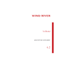
PMC Sierra implemented this change in a manner consistent with the original
design of the status and cause registers. Specifically, the Interrupt Pending (IP)
field of the cause register was extended from 8 to 16 bits, as shown in Figure 1. Six
of these bits are now defined; the remaining two are reserved for future use. This
expansion of the IP field was possible because the added bits were not previously
defined.
17
VxWorks for MIPS, 5.5
Architecture Supplement
However, the status register did not have extra bits available for the needed
additional interrupt mask fields. Therefore, the mask bits had to be placed in a new
register, the interrupt control register (Coprocessor 0, Set 1, register 20), shown in
Figure 1. This field is considered to be an extension of the Interrupt Mask (IM)
field, and mask bits for interrupts 15:8 are placed in bits 15:8 of the interrupt
control register.
Figure 1
RM7000 Register Formats
31
BE
23
0
CE
0
W2 W1 IV
0
8
Interrupt Pending (IP[15:0])
0
Exc Code 0
Cause Register
31
15
8
0
XX CU CO FR RE DS Interrupt Mask (IM[7:0]) KX SX UX KSU ERL EXL IE
Status Register
31
15
0
0
8
Interrupt Mask (IM[15:8])
TE
0
VS
Interrupt Control Register
While four additional hardware interrupts have been added, six bits of the
extensions to the IP and IM fields have been used. Bits 11:8 of these fields
correspond to the newly added hardware interrupt inputs. Bit 12 is used to control
the Timer interrupt source that was multiplexed with Interrupt input 5 in the
original design. For backward compatibility, the Timer interrupt may still be
placed on Interrupt 5, but setting the TE bit (bit 7) of the interrupt control register
frees Interrupt 5 for use solely as a hardware input, and moves the Timer interrupt
to Interrupt 12. The second additional interrupt input is used in conjunction with
the Performance Counters implemented in the RM7000 family. This has been
placed on Interrupt 13.
The additional hardware interrupts on the RM7000 family add to the intPrioTable
that is used by the exception and interrupt handling routines in excLib to call a
user-attached interrupt handler. A typical extended interrupt table is as follows:
18
4
Architecture Considerations
PRIO_TABLE intPrioTable[] =
{
{CAUSE_SW1,(ULONG) IV_SWTRAP0_VEC,
{CAUSE_SW2,(ULONG) IV_SWTRAP1_VEC,
{CAUSE_IP3,(ULONG) IV_IORQ0_VEC,
{CAUSE_IP4,(ULONG) IV_IORQ1_VEC,
{CAUSE_IP5,(ULONG) IV_IORQ2_VEC,
{CAUSE_IP6,(ULONG) IV_IORQ3_VEC,
{CAUSE_IP7,(ULONG) IV_IORQ4_VEC,
{CAUSE_IP8,(ULONG) IV_TIMER_VEC,
#ifdef INCLUDE_RM7K_EXT_INT
{CAUSE_IP9,(ULONG) IV_IORQ6_VEC,
{CAUSE_IP10,(ULONG)IV_IORQ7_VEC,
{CAUSE_IP11,(ULONG)IV_IORQ8_VEC,
{CAUSE_IP12,(ULONG)IV_IORQ9_VEC,
{CAUSE_IP13,(ULONG)IV_IORQ10_VEC,
{CAUSE_IP14,(ULONG)IV_IORQ11_VEC,
{CAUSE_IP15,(ULONG)IV_IORQ12_VEC,
{CAUSE_IP16,(ULONG)IV_IORQ13_VEC,
#endif
};
0x000100,
0x000200,
0x000400,
0x000800,
0x001000,
0x002000,
0x004000,
0x008000,
0},
0},
0},
0},
0},
0},
0},
0},
/*
/*
/*
/*
/*
/*
/*
/*
sw trap 0
*/
sw trap 1
*/
Reserved
*/
Uart
*/
Expansion Conn */
Expansion Conn */
Expansion Conn */
Timer
*/
0x010000,
0x020000,
0x040000,
0x080000,
0x100000,
0x200000,
0x400000,
0x800000,
0},
0},
0},
0},
0},
0},
0},
0},
/*
/*
/*
/*
/*
/*
/*
/*
Expansion Conn
Expansion Conn
Expansion Conn
Expansion Conn
Alternate Tmr
Perf Counter
Reserved
Reserved
*/
*/
*/
*/
*/
*/
*/
*/
Corresponding to the expansion of intPrioTable for extended interrupts, the
sysHashOrder table lookup also required modification. Due to memory
considerations, the size of the lookup table was not increased from 256 (2^8) to
16384 entries (2^14). Instead, the lookup table pointed to by sysHashOrder is left
at 256 entries, and the cause register pending bits are checked in two separate
iterations. The first iteration uses the interrupt sources corresponding to IP[7:0]. If
none of those sources is active, a second lookup is performed using the interrupt
sources corresponding to IP[15:8]. The value from the lookup table in the second
iteration is automatically increased by 8 to place the proper offset into
intPrioTable. As a result of this design decision, interrupt sources in the status
register IM[7:0] are always given higher priority than those sources in the interrupt
control register IM[15:8]. For implementations in which this trade-off is not
acceptable, it is suggested that vectored interrupts be used.
For more details on register formats on the RM7000, please see the PMC Sierra
RM7000 Family User Manual.
Vectored Interrupts on the RM7000
The RM7000 provides an interrupt handling mechanism that alleviates the need
for software to parse interrupt sources and prioritize among them. The RM7000
hardware implements 15 priority levels, each of which has a unique interrupt
handler. Each interrupt source is assigned to a priority level. When the interrupt
occurs, the corresponding handler is automatically executed. Parsing the cause
register, separating exceptions from interrupts, prioritizing among concurrently
active interrupts, checking for masked interrupts, and so forth is no longer
19
VxWorks for MIPS, 5.5
Architecture Supplement
required of the software. This streamlines interrupt processing and enhances
performance.
In support of this functionality, VxWorks has added the data structure
intVecTable. This data structure is an array of structures consisting of two fields:
vector number and interrupt mask. When an interrupt occurs, the RM7000
hardware automatically vectors to the unique handler for that source, based on the
value in its interrupt priority level (IPL) register. The IPL value is used as an index
into the intVecTable array. The interrupt mask field is applied and interrupts are
re-enabled. The vector number is then used as an index into the BSR table to call
the appropriate interrupt service routine, which the user previously installed with
intConnect( ) or intVecSet( ).
Interrupt priority level 15 is reserved. The handler for this level is implemented to
provide backwards compatibility with intPrioTable. Interrupt sources that are set
to use a priority level of 15 use a handler that parses the cause register and uses
intPrioTable as implemented in previous versions of VxWorks.
The intVecTable is very similar to the intPrioTable. For the benefit of those
familiar with intPrioTable, Table 7 provides a summary of the key differences
between this structure and intVecTable.
Table 7
Key Differences Between intPrioTable and intVecTable
Area of Difference intPrioTable
intVecTable
Ordering
Ordered according to the IP field in the
cause register.
Ordered according to interrupt priority levels.
Prioritization
Uses sysHashOrder.
Relies on RM7000 hardware.
Mask Field
Masks only those interrupts that have bits set in
Masks all currently pending interrupts
and any interrupts that have bits set in the the mask field. It has no offset; bit 0 is the mask
for sw trap 0.*
mask field. Its offset matches the cause
register; bit 8 is the mask for sw trap 0.
Demultiplexing
Supported.
Not supported. If required, set the priority level
for those sources that require demultiplexing to
15 and use the intPrioTable.
* Care must be taken in this case. If the hardware calls the highest-priority interrupt, and no other
sources are masked off, a lower-priority pending interrupt will be immediately called once interrupts
are re-enabled.
20
4
Architecture Considerations
With the exception of the following data structure, all other aspects of interrupt
processing are unchanged for the BSP author or application developer (in other
words, intConnect( ) is still used to attach service routines to vectors, and so forth).
#ifdef INCLUDE_RM7K_VEC_INT
typedef struct
{
ULONG
bsrTableOffset;
ULONG
intMask;
} INT_VEC_TABLE;
INT_VEC_TABLE intVecTable[] =
{
{(ULONG) IV_TIMER_VEC,
{(ULONG)
0,
{(ULONG)
0,
{(ULONG)
0,
{(ULONG)
0,
{(ULONG)
0,
{(ULONG)
0,
{(ULONG)
0,
{(ULONG)
0,
{(ULONG)
0,
{(ULONG)
0,
{(ULONG)
0,
{(ULONG)
0,
{(ULONG)
0,
{(ULONG) IV_PERF_VEC,
{(ULONG)
0,
};
#endif
/* index into BSR table
/* interrupt mask
0x3fff},
0x3fff}
0x3fff}
0x3fff},
0x3fff},
0x3fff},
0x3fff},
0x3fff},
0x3fff},
0x3fff},
0x3fff},
0x3fff},
0x3fff},
0x3fff},
0x2000},
0x3fff},
/*
/*
/*
/*
/*
/*
/*
/*
/*
/*
/*
/*
/*
/*
/*
/*
*/
*/
IPL_0 - sysClk
IPL_1 IPL_2 IPL_3 IPL_4 IPL_5 IPL_6 IPL_7 IPL_8 IPL_9 IPL_10 IPL_11 IPL_12 IPL_13 IPL_14 - perf counter
IPL_15 - intPrioTable
*/
*/
*/
*/
*/
*/
*/
*/
*/
*/
*/
*/
*/
*/
*/
*/
The vectored interrupts affect WindView interrupt monitoring. WindView records
interrupt events with a number corresponding to the interrupt’s location in
intPrioTable. For example, int*4 is shown as INT7 on the Event Graph. Because
intVecTable can be used concurrently with intPrioTable, a different scheme must
be used for recording interrupt events that are handled by intVecTable. Interrupts
handled by intVecTable are numbered according to their row (as with
intPrioTable interrupts); however, their numbering begins with the last row of the
intPrioTable. Thus, in the above example, the MIPS timer interrupts are displayed
as INT17 on the Event Graph, and performance counter interrupts are displayed
as INT31. An int*4 interrupt is still displayed as INT7 on the Event Graph because,
in the example, that source is still being handled by intPrioTable. This scheme
guards against potential ambiguity of interrupt events when recorded by
WindView.
For more details on the vectored interrupt register formats on the RM7000, see the
PMC Sierra RM7000 Family User’s Manual.
21
VxWorks for MIPS, 5.5
Architecture Supplement
Memory Management Unit Support
MIPS processors include a minimal memory management unit commonly referred
to as the Translation Lookaside Buffer (TLB). VxWorks does not support use of the
TLB. MIPS processors provide three different modes of operation: user mode,
kernel mode, and supervisor mode. The VxWorks kernel runs under kernel mode
at all times.
Virtual Memory Mapping
The MIPS memory map is arranged in segments that have pre-determined modes
of operation. Unlike some processors that can set specific virtual memory
addresses to any mode of operation, MIPS processors pre-assign certain ranges of
virtual memory addresses to kernel mode or user mode.
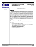
In Figure 2, there are four memory segments: kseg0, kseg1, kseg2, and kuseg.
VxWorks for MIPS operates exclusively in kernel mode and makes use of the kseg0
and kseg1 address spaces. A physical addressing range of 512 MB is available. The
on-chip translation lookaside buffer (TLB) is not supported.
Figure 2
MIPS Memory Map
FFFF FFFF
kseg2
C000 0000
kseg1
A000 0000
kseg0
8000 0000
kuseg
512 MB
0000 0000
0
Virtual Memory
22
Physical Memory
4
Architecture Considerations
To summarize the segments:
kseg0
When the most significant three bits of the virtual address are 100, the 229-byte
(512 MB) kernel physical space labeled kseg0 is the virtual address space
selected. The physical address selected is defined by subtracting 0x8000.0000
from the virtual address. The cache mode for these accesses is determined by
the K0 field of the configuration register, which is initialized in the BSP
romInit( ) routine.
kseg1
When the most significant three bits of the virtual address are 101, the 229-byte
(512 MB) kernel physical space labeled kseg1 is the virtual address space
selected. The physical address selected is defined by subtracting 0xA000.0000
from the virtual address. Caches are always disabled for accesses to these
addresses; physical memory or memory-mapped I/O device registers are
accessed directly.
Memory Layout
The memory layout of a MIPS device operates in kernel segments kseg0 and
kseg1. The value LOCAL_MEM_LOCAL_ADRS, defined in the BSP config.h file,
indicates the start of memory for the system. This value is 0x8000.0000, the virtual
starting address of kseg0.
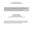
The boot ROM is responsible for setting up the system and loading the VxWorks
kernel into memory. The memory layout is set up by the boot ROM in a three-step
process, as shown in Figure 3. First, the initial boot loading routines located at
ROM_TEXT_ADRS are executed. These routines copy data from ROM_TEXT_ADRS
to RAM_LOW_ADRS and uncompress the data, if necessary. Once in RAM, the boot
process continues by loading the VxWorks kernel. The constants
RAM_LOW_ADRS, RAM_HI_ADRS, and ROM_TEXT_ADRS are located in the BSP
config.h and Makefile files. LOCAL_MEM_SIZE and LOCAL_MEM_LOCAL_ADRS
are located in config.h.
23
VxWorks for MIPS, 5.5
Architecture Supplement
Figure 3
1
MIPS Memory Layout Process
The initial boot-loading
routines are executed.
ROM Image
ROM_TEXT_ADRS
ROM Image
(copied into RAM)
2
The remainder of ROM
is copied into RAM and
uncompressed, if necessary.
RAM_HI_ADRS
LOCAL_MEM_SIZE
VxWorks Image
(loaded by ROM)
3
The VxWorks image is
loaded into RAM.
RAM_LOW_ADRS
LOCAL_MEM_LOCAL_ADRS
The details of the VxWorks image are shown in Figure 4. The figure contains the
following labels:
■
Exception Vectors. Table of exception and interrupt vectors. It is located at
LOCAL_MEM_LOCAL_ADRS.
■
Initial Stack. Initial stack set up by romInit( ) and used by usrInit( ) until
usrRoot( ) has allocated the stack. Its size is determined by STACK_SAVE.
■
System Image. The VxWorks image entry point. The VxWorks image consists
of three segments: .text, .data, and .bss.
■
Interrupt Stack. The stack used by interrupt service routines. Its size is
determined by ISR_STACK_SIZE. It is placed at the end of the VxWorks image,
just after the .bss segment.
■
System Memory Pool. The memory allocated for system use. The size of the
memory pool is dependent on the size of the system image and interrupt stack.
The end of the system memory pool is determined by sysMemTop( ).
24
4
Architecture Considerations
Figure 4
VxWorks Image in MIPS Memory Layout
Address
sysMemTop( )
System Memory Pool
ISR_STACK_SIZE
Interrupt Stack
end
System Image
bss
data
text
Initial Stack
STACK_SAVE
Exception Vectors
RAM_LOW_ADRS
LOCAL_MEM_LOCAL_ADRS
64-Bit Support
VxWorks for MIPS provides real-time applications with access to a 64-bit data
type. This allows applications to perform 64-bit calculations for enhanced
performance.
The long long data type is available for both MIPS32 and MIPS64. However, in
MIPS32, two 32-bit registers are paired to represent a 64-bit value. In MIPS64, such
a value is a true 64-bit value represented by a 64-bit register. For better
performance in your MIPS64 applications, use the long long data type when
representing 64-bit values.
Hardware Breakpoints and the bh( ) Routine
Support for the bh( ) debugger command is provided for those MIPS CPUs that
have hardware breakpoint support. For example, the MIPS cp7000 BSP, which
utilizes the RM7000 CPU, provides hardware breakpoint support for two
hardware breakpoints. To determine if your BSP includes bh( ) support, refer to
your CPU documentation.
25
VxWorks for MIPS, 5.5
Architecture Supplement
5. Reference Material
The information given in this section is current at the time of writing; should you
decide to use these documents, you may wish to contact the manufacturer or
publisher for the most current version.
See MIPS Run. Sweetman, Dominic. Morgan Kaufmann Publishers, Inc.,
San Francisco, CA. 1999.
26