1
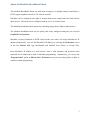
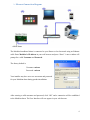
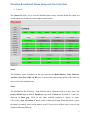
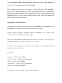
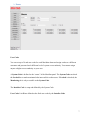
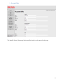
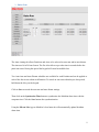
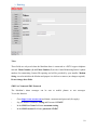
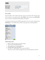
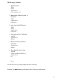
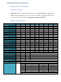
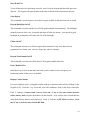
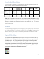
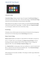
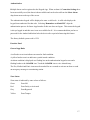
Meridian 8 and Meridian 16 Broadband Alarms User Manual Micron Security Products Ltd November 2014 1 Table of Contents About the Meridian Broadband Alarm ........................................................................................... 3 Ethernet Connection Diagram.............................................................................................. 4 Meridian Broadband Alarm Setup and User Interface ................................................................... 5 Control ................................................................................................................................. 5 Users .................................................................................................................................... 7 Account Info ........................................................................................................................ 8 Auto-Arm ............................................................................................................................. 9 Routing............................................................................................................................... 10 Save .................................................................................................................................... 12 Meridian Keypad Commands ....................................................................................................... 13 Keypad hold down commands ........................................................................................... 13 Change User Code 1 ................................................................................................................. 13 Keypad Command Table ................................................................................................... 13 Access Reader LED’s and Buzzer ................................................................................................ 15 NiteWatch ..................................................................................................................................... 15 Apple and Android Apps .............................................................................................................. 15 Android WiFi Touch Keypad ....................................................................................................... 16 Electrical Specification ................................................................................................................. 20 2 About the Meridian Broadband Alarm The Meridian Broadband Alarm can send alarm messages via multiple internet connections, a PSTN copper telephone network or 3G wireless network. Meridian can be configured with eight or sixteen alarm zones using both wired and wireless input devices. The alarm can be configured with up to 8 or 16 wireless zones. The Meridian has six individual outputs for controlling garage doors, lights or other devices. The Meridian broadband alarm can be quickly and easily configured using the web accessed Graphical User Interface. Meridian is factory defaulted to DCHP which means your router will assign Meridian its IP address automatically. You can find Meridian’s IP address by selecting the Preferences screen in the free Micron Lite App downloaded and installed from iTunes or Google Play. Enter Meridian’s IP address in a web browser, enter a valid username and password when requested and a connection is made to Meridian programming. Alternatively, you can use the ‘Program Panel’ option in Micron Lite’s Preferences screen on your smart phone or tablet to connect to alarm programming. 3 Ethernet Connection Diagram The Meridian broadband alarm is connected to your Router or local network using an Ethernet cable. Enter Meridian’s IP address in your web browser and press “Enter”. A new window will prompt for a valid Username and Password: The factory default is: Username: micron Password: micron Your installer may have set a new user name and password for your Meridian alarm during product installation. After entering a valid username and password, click “OK” and a connection will be established to the Meridian alarm. The User Interface will now appear in your web browser. 4 Meridian Broadband Alarm Setup and User Interface Control The Control tab allows you to view the Meridian alarm’s status, arm and disarm the system and switch outputs by clicking the virtual output control buttons. Status The Meridian’s status is displayed in the top section by the Mains, Battery, Telco, Ethernet, Aux Fuse, Siren Fuse, SMS and RF icons. A green colour indicates that status is OK. When the icon is red a fault condition exists. Zones The Meridian has four Partitions. Each Partition can be configured with up to four Areas. The factory default displays Area A Partition 1 only in the Control tab. Partitions 2, 3 and 4 are displayed in dark grey. Click on any other available partition to display its status. Click on the “Area A Partition 1” button to arm or disarm this Area. When this button is green the Area is disarmed, when red the Area is armed. Greyed Areas indicate those Areas are not assigned within that Partition. 5 The alarm cannot be armed if one or more zones within that Area have a fault condition (red zone colour) and are not programmed for forced arming. All the configured zones in Area A of Partition 1 are listed under the “Area A Partition 1” button. A zone’s status is indicated by its colour. Green indicates the zone is in its normal state. Red indicates the zone is alarmed or a fault condition exists. Click on an individual zone button to bypass that zone if it is bypass enabled and then arm the system. Greyed Zones indicate those Zones are not assigned within that Area. Output Buttons and Function Keys These buttons are displayed at the bottom of the screen. Function Key 1, Function Key 2 and Function Key 3 are mapped to the F1, F2 and F3 buttons on the keypad. Output 1, Output 2, Output 3, Output 4, Output 5 and Output 6 work as toggle switches. Click on them to turn on or off the respective outputs. Clicking the Fire, Medical or Panic buttons will send the fire, medical or panic messages to a Central Monitoring Station (CMS) should that service be enabled. The names of all displayed icons and buttons can be changed to more meaningful labels that better match their actual function. For example: “Partition 1” could be named “House” “Area A Partition 1” could be named “Downstairs” “Zone 1” could be named “Kitchen” “Function Key 1” could be named “Garage Door” “Output 1” could be named “Lights” The installer can make these changes for you during installation. 6 Users User Codes You can set up to 30 end user codes for each Meridian alarm and assign each user a different username and password and a different level of system access authority. You cannot assign anyone a higher access authority to your own. A System Code is defined as the “owner” of the Meridian panel. The System Code can check the Locked box to make nominated tabs inaccessible to other users. If Locked is checked, the Monitoring tab is only accessible to the System Code. The Installer Code is setup and defined by the System Code. User Codes 1 to 30 are defined as the final user codes by the Installer Code. 7 Account Info The Installer Name, Monitoring Station and Site details can be entered in this page. 8 Auto-Arm The Auto Arming tab allows Partitions and Areas to be selected to auto-arm and/or auto-disarm. The time used is in 24 hour format. The Pre-Alert allows a pre-alert time in seconds before the panel auto arms. During this period the keypad will sound an audible alert. Two Auto-Arm and Auto-Disarm schedules are available for each Partition and can be applied to each of the four Areas within each Partition. To cancel an auto arm within the pre-alert period, hold down the 0 key on the keypad. Click on Save to record the auto arm and auto disarm settings. Then click on the Synchronize Time button to synchronize the Meridian alarm time with the computer time. Click the Save button after synchronization. Using the Micron Lite App on Meridian’s local network will automatically update Meridian alarm time. 9 Routing Telco These fields are only used when the Meridian alarm is connected to a PSTN copper telephone network. Phone Number (1) and Phone Number (2) are the Central Monitoring Station’s phone numbers for transmitting Contact ID reporting and will be provided by your installer. Modem String is used to initialize the Modem and prepare it to dial out or answer (no changes required). Do not change these fields. SMS User Name and SMS Password The Meridian’s alarm messages can be sent to mobile phones as text messages. To use this function: - Go to https://www.nexmo.com and obtain a username and password (fees apply). - Say you obtain a Username: testing and Password: 1234567. - In the SMS User Name field enter username=testing - In the SMS Password field enter password=1234567 10 Phone Number Enter the number of the cell phone that will be used for receiving the alarm messages in this field. For instance, if your phone number is 021-1234567, then you need to enter 64211234567 (where 64 is the New Zealand international dialing code identifier). It is important to specify the types of SMS messages that are to be received by a cell phone in the Monitoring tab. Your installer needs to set these message types for you during installation. SMS Messaging Setup 1. 2. 3. 4. 5. Remove ‘Alarm’ from Event 130 and leave blank Type ‘FULL’ in Event 400 (Full Arm) Type ‘PARTIAL’ in Event 402 (Partial Arm) For SMS reported events enter SMS = 1 For Event 354 ‘Communication Fail’ you must select SMS = 1 This alerts to a failure of SMS messaging when alarm communications have been lost. 11 SMS Messaging Examples 1. Quick Arm (1#) ARM FULL Upstairs Area 099 (unknown user) 2. Disarm User Code 1111 (User 1) DISARM FULL Upstairs Area 01 (User 1) 3. Arm User Code 2222 (User 2) ARM FULL Upstairs Area 02 (User 2) 4. Activation on Zone 1 (Kitchen) ALARM Upstairs Area Kitchen 5. Restore on Zone 1 (Kitchen) RESTORE Upstairs Area Kitchen 6. Fire, Medical, Panic Alarm ALARM PANIC or FIRE or MEDICAL Upstairs Area 001 Save Use this tab to save any setting changes that have been made. Remember you must save any tab changes before clicking on a different tab. 12 Meridian Keypad Commands Keypad hold down commands Change User Code 1 Hold down F3 for 2 seconds until two beeps are heard, then press 0 to change User Code 1 (factory default for User Code 1 is 1234). For instance to change the default User Code 1 from 1234 to 5678: F3 (2 seconds)<beep><beep>0 1234 5678# Keypad Command Table Function Quick Arm All Quick Arm A Quick Arm B Quick Arm C Quick Arm D Arm All Disarm All Arm A Arm B Arm C Arm D Disarm A Disarm B Disarm C Disarm D Arm A (duress) Arm B (duress) Arm C (duress) Arm D (duress) Disarm A (duress) Disarm B (duress) Disarm C (duress) Disarm D (duress) Start Walk Test Zone Bypass (Two Digit Zones) Keypad Backlight On/Off Chime On/Off Keypad Fault Sound On/Off Panic Medical Fire Change User Code 1 Cancel Auto Arm Display Control Status Digit 1 0 1 2 3 4 <n> <n> 1 2 3 4 1 2 3 4 1 2 3 4 1 2 3 4 5 9 9 4 (hold) 5 (hold) 6 (hold) 7 (hold) 8 (hold) 9 (hold) F3 (hold) 0 (hold) * Digit 2 # # # # # <n> <n> * * * * * * * * * * * * * * * * # <Z> <Z> 0 Digit3 Digit4 Digit5 Digit6 Digit7 Digit8 Digit9 <n> <n> <n> <n> <n> <n> <n> <n> <n> <n> <n1> <n1> <n1> <n1> <n1> <n1> <n1> <n1> <n> <n> <n> <n> <n> <n> <n> <n> <n> <n> <n2> <n2> <n2> <n2> <n2> <n2> <n2> <n2> # * <n> <n> <n> <n> <n> <n> <n> <n> <n3> <n3> <n3> <n3> <n3> <n3> <n3> <n3> <n> <n> <n> <n> <n> <n> <n> <n> <n4> <n4> <n4> <n4> <n4> <n4> <n4> <n4> # # # # * * * * <n3> <n3> <n3> <n3> <n3> <n3> <n3> <n3> <n4> <n4> <n4> <n4> <n4> <n4> <n4> <n4> # # # # * * * * # <Z> # See Previous Section Numbers on the LCD Keypad indicate: 1 Mains Off (OK) 2 Battery Off (OK) 3 Telco Off (OK) 4 Ethernet Off (OK) 5 Auxiliary Output Off (OK) 6 Siren Fuse Off (OK) 7 SMS Off (OK) 8 RF Off (OK) Press any key to cancel system status fault attention beep On (Faulty) On (Faulty) On (Faulty) On (Faulty) On (Faulty) On (Faulty) On (Faulty On (Faulty) 13 Start Walk Test To test all detectors are functioning correctly, enter 5# on the keypad and then walk past each detector. The keypad will sound to indicate that the each detector has functioned correctly. Zone Bypass This command is used to bypass a zone that is bypass enabled so that the alarm can be armed Keypad Backlight On/Off This command is used to turn the Icon LCD keypad backlight on permanently. The backlight normally turns on when a key is touched and turns off after one minute. Leaving the keypad backlight on permanently will reduce the life of the backlight. Chime On/Off This command can turn on or off the keypad chime function for any zone that has been programmed as a chime zone, such as a shop entry zone for example. Keypad Fault Sound On/Off This command is used to turn off the Icon LCD keypad’s audible fault alert. Panic, Medical, Fire Hold these keys to activate the alarm and send a panic, medical or fire emergency to a monitoring station if that service is enabled. Display Control Status If a fault condition exists, a triangular symbol with an exclamation mark will be flashing on the keypad’s LCD. Press the * key to list and view fault conditions. Refer to the above fault table. Fault ‘2’ indicates a battery fault condition. Press the ‘2’ key to view any wireless detector with a battery fault. Replace the batteries in that detector. If no wireless zone is listed then the main alarm backup battery needs replacing. Fault ‘8’ indicates an RF Fault condition. Press the ‘8’ key to view the zone with the RF fault. 14 Access Reader LED’s and Buzzer If an access reader is configured to your Meridian alarm, the reader’s green and red LED’s and buzzer are used to indicate the alarm and door status as follows. Armed Disarmed Arming Disarming Slow Flash Green LED Red LED Buzzer Partially Armed or Disarmed On Off Door Unauthorised Opening Card Fast Flash On Flash Mimics Keypad Flash Mimics Keypad 2 Beeps Long Beep Hold a card or tag against the card reader for a few seconds to arm the system. Swipe a card to open the door and disarm the system if it is armed. Two short beeps and a flashing green LED indicates the alarm has been disarmed and access has been granted. One long beep indicates access has been denied. NiteWatch If a Nitewatch night arming station has been configured to your system, press the Arm button to arm Meridian (and disarm if that function is enabled). Press the Emergency button to activate the alarm and send a panic message to the monitoring station if that service has been enabled. Apple and Android Apps Download Meridian’s ‘Micron Lite’ App from Apple’s iTunes store, or Google Play store for the Android version. The App provides alarm and output control from your Apple or Android smartphone or tablet. The App will automatically retrieve Meridian’s local network address details and load these into the ‘Preferences’ page of the App. If the username and password are different to the factory defaults (micron, micron), enter the correct username and password and touch Save. Valid usernames and passwords will reveal the App Home page. Refer to ‘About’ in the App for a full description of Micron Lite functionality. 15 Android WiFi Touch Keypad Connection Settings Connection Settings is displayed when the App is first opened. Local Network Settings are entered automatically by the alarm. There is no need to make changes. Local Network Settings can only be saved on the Meridian’s local network and are then hidden. When making and saving changes on remote networks you must hide Local Network Settings, if this has been opened, before saving changes. Any fields visible in the Connection Settings view will attempt to validate and overwrite current alarm settings. Panel Settings If Meridian’s factory default username (micron) and password (micron) have been changed you must enter the new username and password in Panel Settings and touch Save. Remote Network Settings Remote Network Access can be enabled via a Static Public IP or DNS address or Dynamic IP Service. To enable remote access to Meridian, open Remote Network Settings to enter the Panel Remote Port and a valid Static Public IP, DNS or Dynamic IP Service setting in the appropriate fields. Turn on the Use Remote Connection Settings switch. If a ‘Connection Error’ message appears, check your Android device’s network connection and that it is connected on the same network as the Meridian alarm. Touch Connection Settings to check that all setup parameters are entered correctly. When all changes have been made, touch Save. If all settings are valid the App’s authentication keypad will display. 16 Authentication Multiple alarms can be registered to the Keypad App. When an alarm’s Connection Settings have been successfully saved, the alarm is then available and can be selected from the Select Alarm drop down menu at the top of the screen. The authentication keypad will be displayed to enter a valid code. A valid code displays the keypad icons authorised for that code. Selecting ‘Remember as default PIN’ skips the authentication process for future App launches if this user does not logout. This means the keypad is always logged in and this users icons are available for all. It is recommended that you have a password for the Android tablet that locks the device after a period when using this feature. The factory default system code is 1234. Function Panel General App Rules A red border to an icon indicates an armed or fault condition. A yellow border to an icon indicates a partial armed condition. An alarm condition is displayed as a flashing bar on the authentication keypad screen and a flashing border to the iALARM icon. Touch the iALARM icon to view alarm history. The Fire, Medical and Panic icons must be touched for two seconds to activate an alarm or send an emergency message to a monitoring station. Zone Status Zone status is indicated by zone colour as follows: Green Zone OK Red Zone Faulty or Activated Grey Zone Bypassed Yellow Zone Tamper 17 Default Setup Icons House Fire White Cross Exclamation Car Light Temperature iALARM Laptop Wheel iAREA iZone X Camera LOGIN PIN (Arm/Disarm All) (Fire) (Medical) (Panic) (Function Key 1) (Function Key 2) (Function Key 3) (Alarm History) (Program Alarm) (Panel Status) (Area Status) (Zone Status) (Bypass Zones) (Live Video) (Change Login) (Change PIN) Touch the Action Bar (menu point) on any screen to reveal menu options. ‘Logout’ This logs out the App and requires a valid code to be re-entered. ‘Refresh’ The App continually updates alarm status on the local network. Touch Refresh to update Meridian alarm status on a remote network or when Configuration Settings have been changed. Camera Live Video Tap on the camera icon to open Live Video streaming for cameras. Select a camera from the drop down menu at the top of the screen. Tap on Options to add a new camera or update a current camera’s settings. Select one of the five communication protocols for the camera from the drop down menu. Enter a username and password if required by the camera for authentication. Enter the Local IP address and the Local Port the camera is using. Enter additional parameters required by the camera in the Extra URL Parameter field. Camera URL format: protocol://Username:Password@IPaddress:Port/Extra_Parameters Example Format: rtsp://admin:[email protected]:80/live/h264 18 Turn on Enable Remote Access to access the camera remotely. Enter the Remote Port of the camera. Turn on Use Panel Remote IP if the camera and the Meridian alarm use the same external IP address. Otherwise, turn off Use Panel Remote IP and enter the camera’s remote IP address. Touch Save to save all settings and close the setup window. Preferences Select User: The User saved in Connection Settings is the default master user. The master user can manage other user preferences and enable those users to manage their own preferences. Screen Icons: Select the number of icons to be displayed for this valid code from the drop down menu. Default is 16. Auto Lock: Select the time in minutes from the drop down menu after which the icon screen will lock and require a valid code to be re-entered. Default 5 minutes. Image Selection: Touch an icon to scroll, display and select Function Selection: Select the function from the drop down menu to apply to this icon. Touch Update to save icon selections. 19 Electrical Specification AC Input 14.2V DC voltage from switch mode power supply Accessory Power 13.8V DC voltage, 500mA maximum current rating Siren Output 13.8V DC voltage, maximum 1.5 Amp current rating to non-inductive load Output 1, Output 2 and Output 6 13.8V DC voltage, maximum 1.5 Amp current rating to non-inductive load Output 3, Output 4 13.8V DC voltage, maximum 250mA current rating Battery 12 Volt, 7.2A/H Siren Fuse, RS485 Keypad Bus Fuse and Battery Fuse 1.85 Amp resettable fuse 20 WARRANTY 1. Subject to clause 2 below, micron warrants this product against defects in materials and workmanship for a period of 24 months from the date of delivery to the purchaser as follows: (a) Micron will repair or replace free of charge any goods or part thereof found to be defective by reason of faulty material or workmanship. (b) The purchaser must give micron notice of the alleged defect within 14 days of it becoming apparent and must return the defective goods or part thereof to micron. 2. This warranty does not apply or extend to: (a) Any product altered or repaired by any person other than micron so as in micron’s sole judgment to adversely affect the product. (b) Damage, malfunction or failure arising from accident, misuse or misapplication, neglect, modifications, use of unauthorised replacement parts or accessories, exceeding the specific ratings, improper voltage or connection of any wire to any part of the circuit board other than the terminal block. (c) Any product where the rating label or serial number is removed or altered. (d) Any consequential or indirect loss. Notice of Liability While every effort has been made to ensure the accuracy of this document, neither Micron Security Products Ltd nor any of its official representatives shall have any liability to any person or entity with respect to any liability, loss or damage caused or alleged to be caused directly or indirectly by the information contained in this manual. Should any error or inconsistency be found, please notify us. Micron Security Products Ltd reserves the right to make changes to features and specifications at any time, without notification, in the interest of ongoing product development and improvement. Designed and manufactured by 21