1
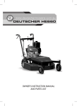
DEUTSCHER
CHIPPER SHREDDER 650
Operation and Maintenance
Manual
www.deutschermowers.com.au
INDEX
2
3
General Description
4
Initial Assembly
5
Safety Procedures
7
Decals
8
Storage & Transporting
9
Pre-Start Checks and Starting
10
Chipping
11
Shredding
12
Maintenance
16
Spare Parts and Warranty
GENERAL DESCRIPTION
Engine fuel cap
Hopper
Clutch lever, at rear
Engine oil fill hole/
dipstick under cap
Chipper tube
Engine oil drain
Belt guard
Deflector pin
Upper grate pin
Discharge deflector
Shredding chamber
Lower grate pin
The Deutscher Chipper Shredder is designed to chip branches up to 65mm diameter (via Chipper Tube) and shred
a range of garden waste including branches up to 12mm diameter (via Hopper). A Swedish Viking steel chipper
blade attached to a rotating disc behind the chipper tube does the chipping, and nine hardened steel flails inside
the shredding chamber rotate at high speed to shred lighter material. Material does not exit the unit until it is
small enough to pass though the holes in the internal perforated grate. Most material will not clog the perforated
grate. A bar grate for processing soft vegetable matter is available as an optional extra. A clutch has been fitted
to allow easy starting.
3
INITIAL ASSEMBLY
The following instructions apply when the unit has not been assembled.
1. Do not put oil into the engine until the unit is assembled.
2. Remove the discharge deflector, then lower the shredding chamber onto its front as shown
below. Fit the front leg using the four countersunk screws provided.
Important. The screws must be fitted from the inside of the chamber, with the nyloc nuts on the
outside of the chamber.
3. Fit the rear axle assembly using four 20mm bolts and nyloc nuts.
4. Attach the wheels using 4 plain washers and 2 “E” Clips. (The slotted holes in the machine
body allow adjustment of the axle height and axle level.)
5. Put the shredding chamber onto its wheels, then attach the discharge deflector. The clutch
handle can now be attached. The washers are placed either side of the lever, then attach the
nyloc nut. The nyloc nut must not be fully tightened, or the lever will not move.
6. Attach the hopper to the shredder chamber using the two 10mm nyloc nuts provided.
See below.
‘U’ Handle
10mm Nut
7. Attach the ‘U’ handle to the hopper sides using the four M8x40 bolts provided (Nyloc nuts
inside hopper).
7. Fill the engine with 600ml of engine oil (See engine manual for correct oil). Check the level is
correct by using the dipstick. Add unleaded petrol to the fuel tank.
WARNING WHEN HANDLING PETROL, KEEP AWAY FROM ANY NAKED FLAMES, THIS
INCLUDES THE PILOT LIGHT ON GAS APPLIANCES. PETROL FUMES ARE HIGHLY VOLATILE.
8. Become familiar with this booklet before starting or operating the chipper shredder.
4
SAFETY PROCEDURES
PREPARATION
1. Do not allow children to operate this equipment.
2. Do not operate this equipment in the vicinity of bystanders.
3. Do not run the unit in an enclosed area since the exhaust from the engine contains some
carbon monoxide, which is a colourless, odourless, tasteless and poisonous gas.
4. Wear safety glasses and hearing protection at all times when operating the machine.
5. Avoid wearing clothing that is loose fitting or has hanging cords or ties.
6. Only operate the machine in open space, not close to a wall or other fixed object, and on a
firm, level surface.
7. Do not operate the machine on a paved or gravel surface, where ejected material could
cause injury.
8. Before starting the machine, check that all screws, nuts, bolts, and other fasteners are
properly secured and that guards and screens are in place.
9. Replace damaged or unreadable labels.
10. Use extra care in handling fuels. They are flammable and the vapours are explosive. The
following points should be observed:
• Use only an approved container.
• Never remove the fuel cap or add fuel with the power source running. Allow engine and
exhaust components to cool before refuelling.
• Do not smoke.
• Never refuel the machine indoors.
• Never store the machine or fuel container inside where there is an open flame, such as
a water heater.
• If fuel is spilled, do not attempt to start the power source, but move the machine away
from the area of spillage before starting.
• Always replace and securely tighten the fuel cap after refuelling.
• If the fuel tank is drained, this should be done outdoors.
5
SAFETY PROCEDURES
OPERATION:
1. Before starting the machine, look into both the chipper tube and the hopper to ensure they
are empty.
2. Keep your face and body away from the feed intake opening.
3. Do not allow hands or any other part of the body or clothing inside the hopper, chipper tube,
discharge area, or near any moving part.
4. Keep proper balance at all times. Do not overreach. Never stand at a higher level than the
base of the machine when feeding material into it.
5. Always stand clear of the discharge area when operating the machine.
6. When feeding material into the machine be extremely careful that pieces of metal, rocks,
bottles, cans or other foreign objects are not included.
7. If the cutting mechanism strikes any foreign objects or if the machine should start making
any unusual noise or vibration, shut off the power source and allow the machine to stop.
Disconnect the spark plug wire from the spark plug and take the following steps:
• Inspect for damage.
• Check for, and tighten, any loose parts.
• Have any damaged parts replaced or repaired with parts of equivalent specifications.
8. Do not allow processed material to build up in the discharge zone; this may prevent proper
discharge and can result in kickback of material through the feed intake opening.
9. If the machine becomes clogged, shut off the engine and disconnect the spark plug wire
before clearing debris.
10. Keep the engine clear of debris and other accumulations to prevent damage to the engine,
overheating or a possible fire.
11. Keep all guards and deflectors in place and in good working condition.
12. Do not tamper with the engine governor settings; the governor controls the safe maximum
speed and protects the engine and all moving parts from damage caused by over-speeding.
Seek authorised service if a problem exists.
13. Do not move the machine while the engine is running.
14. Shut off the engine using the electrical switch whenever you leave the work area.
15. Do not tilt the machine while the power source is running.
16. Even when wearing safety glasses, do not look into the hopper and push the rubber flap
aside while the machine is running. Material can be ejected at high speed.
6
DECALS
The decals shown below are attached to each new machine. It is the operators responsibility to
ensure these decals are in place and legible. They can be purchased from Deutscher Mowers
Pty Ltd as a set. See “Spare Parts”, in this manual.
On the discharge chute and
On the side of hopper.
beside the chipper tube.
On belt guard near clutch lever.
On the rear of the machine, below the hopper.
On the front of the hopper.
7
STORAGE & TRANSPORTING
STORAGE
Always allow the machine to cool before storing.
Store the machine in a dry area away from children and where petrol vapours cannot be ignited
by a spark, such as a welder, or a flame from say the pilot light in a gas appliance.
When storing the unit for longer than three months, it is a wise practice to run the fuel tank
dry beforehand. Fuel can lose volatiles and becomes ”stale” when left in the tank. This may
prevent starting in the future.
TRANSPORTING
Warning: As stated above, never move the unit when it is running.
1. To move the unit around the garden, stand at the back of the unit facing the lowest edge
on the top of the hopper. Grasp the hopper by both sides using both hands, and pull the top
of the hopper towards you until the unit is evenly balanced over the rear wheels. Push the
unit forward; ensuring it remains evenly balanced over the rear wheels. Try not to descend
steep slopes, and maintain a secure footing if you are descending slopes. NEVER DESCEND A
SLOPE WITH A BYSTANDER BELOW YOU. Do not traverse across steep slopes. The unit may
fall sideways.
2. Do not attempt to move the unit up or down stairs unless you are capable of holding the
weight. Always proceed slowly down stairs with the unit below you. Lower the unit onto each
step carefully, to avoid high impact loads on the wheels and axle. When climbing stairs, again
ensure the unit is below you, and walk backwards holding both sides of the hopper firmly.
3. Transporting from one location to another is best accomplished using a trailer behind a car or
a utility. Always tie the unit in place securely. To prevent the unit falling over, it is safer to remove
the hopper. KEEP THE UNIT UPRIGHT, AS OIL WILL SPILL OUT OF THE ENGINE THROUGH THE
EXHAUST OR THE CARBURETTOR, IF IT IS TILTED SIGNIFICANTLY. If the chipper shredder
must be transported in a station wagon or a car boot, it is easiest to remove the hopper and the
engine. If the engine contains oil, it must be transported upright, but the unit can then be laid
on its side. (Removing the legs and the hopper for transport is not a safe option, as the resulting
assembly is “top heavy” and may fall over inside the vehicle.)
8
PRE-START CHECKS & STARTING
PRE-START CHECKS
• Ensure you are wearing safety glasses and hearing protection.
• Avoid wearing loose fitting clothing.
• Place the machine on a level “dirt or grass” surface.
• Check that all fasteners on the machine are secure and all guards are in place.
• Check engine oil level.
• Ensure the hopper, the shredding chamber and the chipper tube are clear.
• Keep bystanders away.
• Follow safety instructions (Page 5) when filling the fuel tank.
STARTING
1. Disengage the clutch. Pull the lever up.
2. Turn the fuel tap to “ON”.
3. Switch on the ignition. Push the “ON” end of the red toggle switch inwards.
4. Push the throttle lever to “FAST”. (Rabbit)
5. Move the choke control to “CHOKE”.( Generally not necessary if the engine is hot.)
6. Stand facing the engine control panel and slightly to the right of the panel. With your left hand
holding the top of the hopper and your right hand holding the starting cord handle, swiftly pull
the starting handle to the right. Repeat until the engine starts. If the engine seems to be flooded,
you may need to try a few pulls of the starter with the choke fully off.
7. As soon as the engine fires, start reducing the choke setting.
8. Once the engine sounds stable, and the choke is fully off, slowly push the clutch lever down
until it reaches the end of its stroke.
9. Check that the rotor is spinning by observing the end of the shaft near the chipper tube.
10. Reduce the throttle setting to the position you need for effective machine operation. Large
diameter branches or a heavy shredding load will require full throttle.
IMPORTANT: The clutch is fitted to make starting easier. It may not fully disengage the drive
to the rotor, especially when the drive belt is new. NEVER rely on the clutch to disengage the
drive. ALWAYS switch off the engine and disconnect the spark plug lead before clearing a
jam or checking the machine.
CHOKE
FUEL TAP
THROTTLE
6.5
ON-OFF SWITCH
STARTER HANDLE
Control Panel Layout (INTEK)
Control Panel Layout (Honda)
9
CHIPPING
CHIPPING
Warning! Do not place hands or fingers into the chipper tube. Keep children away from the
machine when it is operating. Never leave the engine running and unattended.
1. The Deutscher chipper shredder can chip branches up to 65mm diameter. Should a branch
contain sharp bends, the bends can be cut 2/3 through with a bow saw. Then the branch can be
forced straight and will easily feed into the tube. Very short branch pieces can be processed,
by pushing them in with the next branch.
2. If the machine is slowing significantly as a branch is being processed, reduce the feeding
rate. In this case, the wood may be very dry and hard, or the chipper blade may need sharpening.
See maintenance instructions.
3. The ends of branches with many smaller branches attached, can normally be dropped into
the hopper, providing the largest branch is no greater than 12mm diameter.
4. Some branches have strong bark which peels off as the branches are being chipped, and the
bark then winds around the rotor shaft, causing a bearing to get hot. Rotating branches slowly
as you chip, should solve this problem. DO NOT TRY AND CHIP PALM LEAVES, AS THEY CAN
ALSO CAUSE THE BEARING TO OVERHEAT.
5. If you wish to collect the shredded material, it can be discharged onto a plastic, or similar,
sheet. To collect the material, simply switch off the machine, move it backwards off the sheet,
and pick up the sheet by its four corners.
Please note: The machine should not be tilted while it is running, as the engine may seize.
6. If you notice the rotor is not turning, (by looking at the end of the shaft next to the chipper
tube), and if the clutch lever is in the “engaged” position, then the shredding chamber may be
clogged or the belt may need tightening or replacing. See maintenance instructions. Similarly,
if you can smell the belt burning, it will need adjusting or replacing. STOP THE UNIT AS SOON
AS ANY OF THESE FAULTS ARE DETECTED. YOU MAY SAVE THE BELT. See next section for
clearing a blocked shredding chamber.
7. In the unlikely event that a branch becomes jammed in the chipper tube, stop the machine
and disconnect the spark plug lead from the spark plug. You may need to remove the hopper so
you can rotate the rotor by hand, to disconnect the chipper blade from the branch. Use a pair of
pliers, a screwdriver or similar tool to withdraw the branch out of the chipper tube.
10
SHREDDING & SAFE STOPPING PROCEDURE
SHREDDING
Warning! In general, materials will “self fed” into the hopper. Do not FORCE material into the
hopper with your hands. Push material with a green branch (no larger than 20mm diameter) or
a piece of softwood. If materials become jammed, a safer practice is to turn off the machine,
remove the offending material, restart and feed it in again.
Warning! Wear eye protection and hearing protection. Although every effort has been made
to reduce the velocity of chips that may fly back up the hopper, we could not test every variety
and shape of wood. It is therefore a wise operating practice to keep your head out of the
opening.
Warning! Be extremely careful that you do not inadvertently collect metal, bottles or other
hard objects when you pick up material to drop into the hopper. The hard material may fly
back, or it may even break components inside the machine.
1. Branches smaller than 12mm diameter, leaves, weeds and other organic material can be
shredded. If you notice that the material is not coming out the discharge chute, then the rotor
is jammed or the grate is blocked. To unblock the grate or to free the rotor, turn off the engine,
disconnect the spark plug lead from the spark plug, pull out the top grate pin, raise or remove
the discharge deflector, lower the screen and remove the offending material from the shredding
chamber. Replace all components before restarting.
2. Should the grate continue to block, try mixing some dry material or small branches with the
soft material being shredded. If this also fails, you may consider purchasing our optional bar
grate. The bar grate replaces the perforated grate, and is held in place with the same two
pins.
3. Be very careful when feeding branches into the hopper, as they can rush out of your hands
in an instant. NEVER WRAP MATERIAL AROUND YOUR HANDS. ALWAYS BE PREPARED TO
INSTANTLY RELEASE THE MATERIAL. DO NOT SHRED PALM LEAVES. LONG MATERIAL
SUCH AS VINES SHOULD BE CUT INTO LENGTHS NO LONGER THAN 500mm.
4. Do not allow the discharged material under the machine to build up to the point where it
is preventing further material from being discharged. Never put your hands or feet under the
machine when it is running. Use an implement or a stick to push material aside.
5. Control the rate of feeding the hopper to minimise large changes in engine speed. This will
ensure your belt lasts longer and may prevent a blocked shredding chamber or a clogged
hopper.
SAFE STOPPING PROCEDURE
LEAVE THE CLUTCH ENGAGED WHEN STOPPING THE ENGINE. THIS WILL REDUCE THE ‘RUNON’ PERIOD OF THE ROTOR AND WILL REDUCE BELT WEAR. After the rotor has stopped, the
clutch can be moved to the disengage position in readines for the next start-up.
11
MAINTENANCE
BASIC MAINTENANCE
Tools required :
5mm Allen Key (chipper blade replacement)
13mm ring / open ended spanner.
17mm ring / open ended spanner
General
When the machine is stopped for servicing, inspection, or to change an accessory, shut
off the engine, disconnect the spark plug wire from the spark plug and make sure that all
moving parts have come to a complete stop. Due to the magneto starting system, the engine
may start when the cutting means is moved unless the ignition switch is off and the spark
plug wire is removed from the spark plug. Never rely on the clutch to positively disengage
the drive mechanism. Allow the machine to cool before making any inspections, adjustments
etc.
Oil check and replacement
The engine oil level should be checked regularly, every 4 hours of operation. For oil
replacement, see the engine booklet.
Chipper blade replacement/ sharpening
The chipper blade will become blunt with extended use, particularly if you are chipping dry
hardwood. You can feel when the blade is blunt, as the processing time is longer and the
engine is more likely to slow down under heavy loading. To sharpen the blade:
• Switch off the engine and remove the spark plug lead from the spark plug.
• Using a spanner, remove the two 10mm nuts that hold the hopper in place. Remove the
hopper.
• Using a 13mm spanner, remove the small maintenance cover plate, adjacent to the
chipper tube.
• With the clutch lever disengaged, turn the rotor until the chipper blade is opposite the
opening created by removing the cover.
• Using a nail or a similar sharp object, clean the allen key holes in the two countersunk
screws that retain the chipper blade.
• With the 5mm allen key on the outside and a 13mm spanner on the inside, remove the
two screws that secure the chipper blade to the rotor disc.
• Remove and inspect the chipper blade. The edge can be sharpened using a fine grinding
wheel. It should be sharpened at 45 degrees to the top surface. Remove only a minimum
of material, until you feel that the edge is sharp. Initially the blade is 32mm wide. With
repeated resharpening, the blade will reach 30mm wide. At this time it should be replaced,
as the rotor will not be in balance.
• Before refitting the chipper blade, clean the surface of the disc behind the blade and
ensure that the blade is sitting flat on the sloping machined surface. Replace the two
screws if they appear worn or damaged. Always use new 8mm nyloc nuts and tighten
them securely. DO NOT USE PLAIN 8MM NUTS. THE CHIPPER BLADE COULD FLY OUT OF
THE CHAMBER OR SMASH INTO THE CHIPPER TUBE IF THE BOLTS BECOME LOOSE.
• Rotate the rotor disc slowly by hand, and check that the chipper blade does not hit the
inside end of the chipper tube.
• Replace the maintenance cover plate and the hopper.
12
MAINTENANCE
Air filter cleaning
Check the condition of the air cleaner regularly, in dusty conditions every 4 hours. See engine
book for cleaning details.
Drive belt adjustment / replacement
The drive belt may become loose after an initial settling in period, after very heavy loads
have been applied or after an extended period of use. You can see if the belt is slipping
by observing the end of the rotor shaft, adjacent to the chipper tube. When “slipping” is
observed, do not continue to use the machine. Tighten the belt as follows:
• Switch off the engine and remove the spark plug lead from the spark plug.
• Using a 13mm spanner, remove the plastic belt guard.
• Observe the condition of the belt. If it is severely frayed or has a burnt section, it will need
to be replaced.
• Loosen the nut (1 - see diagram below) furthest from the belt on the threaded rod attached
to the clutch lever, using a 13mm open ended spanner. See sketch below.
• With the clutch lever in the “up position, wind the nut (1) about 2mm away from the
adjacent boss (3), then wind the other nut (2) outwards until both nuts are firmly in contact
with the boss.
• Push the clutch lever down fully and check the belt tension. The far side of the belt should
deflect about 12 mm when pushed firmly inwards. See sketch below.
• If the belt is not yet tight, repeat the process.
• Should you run out of adjustment, the belt will need to be replaced.
• Tighten both nuts against the boss, then replace the plastic belt guard. Do not overtighten the belt guard nuts, or you will distort the guard.
• To replace a belt, simply wind nut (2) fully inwards and replace the belt by winding it onto
the two pulleys. IMPORTANT: ENSURE THAT THE BELT IS INSIDE THE TWO BELT GUIDE
PINS THAT ARE ATTACHED TO THE SIDE PLATE OF THE ENGINE. FAILURE TO CHECK THIS
COULD RESULT IN A RUINED BELT. Adjust the belt tension as described above.
12mm deflection
UP
(3)
(1)
(2)
Drive belt
DRIVE BELT ADJUSTMENT
13
MAINTENANCE
DETAILED MAINTENANCE
Tools Required:
1/8” Allen Key
8mm ring spanner and small socket spanner.
18mm open ended spanners.
A bearing puller may also be needed.
Shifting spanner, 200mm approx.
Philips screwdriver at least 210mm long, or a 6mm diameter pin at least 250mm long.
General
The rotor assembly should be inspected after every 20 hours of use or after a solid impact,
by removing the hopper. Should any parts appear badly worn, cracked or bent, they must
be replaced before the machine is used again. Always replace the flails and/or the rotor
spacers in sets, to keep the rotor in balance.
The flails can be rotated if they are worn on one side.
Removal and replacement of the flails
• Switch off the engine and remove the spark plug lead from the spark plug.
• Remove the hopper and the maintenance cover plate.
• Disengage the clutch.
• Remove the two bolts from one of the flail rods, then align the rod with the 7mm hole in the
side plate. The hole is normally obscured by the belt guard, and is opposite the maintenance
cover hole.
• Push the shaft of a Philips screwdriver through the 7mm hole and drive the flail rod out the
opposite side plate of the machine, through the maintenance cover hole. You may need to
tap the end of the screwdriver.
• Collect all the flail components and place them in a separate pile.
• Select the other two flail rods in turn and repeat the operation, keeping the parts
separate.
• Inspect all parts for significant wear or cracks. Replace any faulty parts.
• When re- assembling, it is wise to swap the flail rods to another location, so the flails wear
the rods at different points. Observe the diagram below to ensure you place the flails in the
correct position. It is particularly important that the flail against the chipper disc is on the
rod opposite the chipper blade. See (A) below.
• Replace the bolts if any wear or damage is observed. This includes the threads.
• Always replace the six 5mm nyloc nuts.
2
Chipper
Blade
A
1
4
Chipper
Disc
4
3
3
4
4
Flail Rod
2
1
Flail
14
See table page 15 for rotor spacer sizes & part numbers.
MAINTENANCE
Rotor Spacers - refer diagram page 14
Spacer No.
1
2
3
4
Part Number
3180
3179
3181
3182
Length mms.
18
36
51 (with hole)
51 (no hole)
Quantity
2
2
2
4
Engine Replacement
• Switch off the engine and remove the spark plug lead from the spark plug.
• Remove the hopper.
• Remove the discharge deflector.
• Remove the belt guard.
• Undo the four 8mm engine bolts using 13mm spanners.
• Remove the drive belt.
• Lift the engine off the machine.
Rotor Removal
• Remove the engine as described above.
• Remove the front and rear legs from the shredding chamber.
• Undo the boss screws on the rotor pulley.
• Using a puller, remove the pulley from the rotor shaft.
• Undo boss screws on rotor bearing each side of rotor
• Take the 8mm bolt from the end of the rotor shaft, on the chipper tube side.
• Undo the seven 10mm nuts securing the chipper tube side plate to the engine mounting
plate and the curved back plate. Undo the two 8mm bolts securing the chipper tube plate to
the small plate under the engine mounting plate.
• Tap the chipper tube plate off the shredding chamber using a plastic hammer.
• Tap the rotor through the back bearing using a plastic hammer.
• Inspect the bearings for signs of overheating, loss of grease, looseness or “lumpy”
operation when turned. Inspect also the fit of the bearings in the housings. They must be a
very firm sliding fit. Replace bearings and housings unless they appear perfect.
• Also inspect the keyway on the rotor shaft, for the pulley. Repair the keyway if it appears
damaged, or replace the rotor.
Note. When re-assembling, use a thread locking compound on the pulley boss screws and
replace the key if it appears worn. After assembly, check that the chipper blade does not
contact the inside end of the chipper tube by rotating the rotor by hand.
15
COMMONLY USED SPARE PARTS
DEUTSCHER CHIPPER SHREDDER ROTOR ASSEMBLY
Exploded View & Parts
Flail bolt
and nut (10 & 11)
(5) Blade &
bolt set
(2)
Flail Rod (7)
(4)
(3)
(5b)
Blade nut
(5a) Blade
bolt
A
(3)
(1)
(9) Rotor
Welded
Assembly
(4)
(4)
(4)
(2)
(1)
Flail 6
ROTOR COMPONENTS
16
Item No.
Part Number
Item Description
Qty Per
1
3180
Flail spacer 18mm (2 per assembly)
2
2
3179
Flail spacer 36mm (2 per assembly)
2
3
3181
Flail spacer 51mm with hole ( 2 per assembly)
2
4
3182
Flail spacer 51mm without hole ( 4 per assembly)
4
5
3112
Chipper blade set incl. screws and nuts (One blade, two nuts and two
screws per set)
1
5a
3178
Chipper blade bolt
2
5b
1099
Chipper blade nut
2
6
3111
Flail blade set ( 9 flails per set)
1
7
3121
Flail Rod (3 required)
3
8
3251
Flail spacer set complete (Includes bolt & buts)
1
9
3184
Rotor welded assembly
1
10
3183
Flail Bolt
6
11
1260
Flail Nut
6
12
3391
Flail Blade (1)
9
COMMONLY USED SPARE PARTS
DEUTSCHER CHIPPER SHREDDER
40
40
Exploded View
17
COMMONLY USED SPARE PARTS
DEUTSCHER CHIPPER SHREDDER
Exploded View Parts
18
Item No.
Part No.
Part Description
Qty per
1
3210
Hopper Assembly
1
2
3129
Rubber flap
1
3
3186
Engine Intek 6.5
1
3
3204
GX200 Honda T1 QXU
1
4
3162
"Key 3/16"" sq x 37mm"
2
5
3161
Belt A 31
1
6
3131
Pulley Guard
1
7
3283
Handle Hopper
1
8
3128
Flap wire
1
9
3114
Engine Pulley
1
10
3123
Chute attach plate assy
2
11
3135
Engine mounting plate assembly
1
12
3185
Belt guide
2
13
3147
Deflector Pin, 1/4 dia zp
1
14
3146
Front deflector
1
15
3154
Grate Pin ( top) Assembly
1
16
3144
Maintenance cover plate
1
17
3116
Grate (19mm Assembly)
1
18
3175
Bearing & housing
2
19
3158
Lynch pin
1
20
3137
Folded Plate
1
21
3159
Grate Pin (lower) Assembly
1
COMMONLY USED SPARE PARTS
DEUTSCHER CHIPPER SHREDDER
Exploded View Parts
Item No.
Part No.
Part Description
Qty per
22
3177
ROTOR ASSEMBLY incl blade.
1
23
3172
Stepped pivot, clutch mechanism
1
24
3203
Stud 8mm x98 (guard attach)
2
25
3148
Front leg (powder coated)
1
26
3153
Wheel
2
27
3141
LH Main Plate assembly
1
28
1171
R clip
1
29
3138
RH Main Plate assy
1
30
3150
Rear axle assembly
1
31
3132
Back plate assembly
1
32
3173
Clutch lever
1
33
3168
Stepped bush, idler pivot
1
34
3169
Belt tensioner assy
1
35
3164
Idler pulley arm assy
1
36
3163
Idler pulley
1
37
3113
Rotor pulley
1
38
1314
Axle circlip
2
39
3200
Bar grate assembly, (optional)
1
40
1315
Wheel Washers
4
3187
Decal Set
1
3189
User's Manual
1
19
WARRANTY POLICY
• DEUTSCHER MOWERS PTY. LTD. will repair or replace, free of charge, any chipper shredder or part of the unit
that is defective in materials or workmanship (or both) for a period of 24 months from the date of purchase. If
parts or units are replaced, the replacement period will be no longer than 3 months.
• This does not cover normal wear, abuse or servicing procedures not in accordance with the user’s manual.
Parts such as blades, blade bolts, tyres and v-belts, that can be subject to use beyond their normal intended
working limits, are also excluded.
• This warranty is void if parts other than genuine parts have been used or if repairs or modifications have been
made without the manufactures written authority.
• This warranty does not obligate the manufacturer, agents or dealers to cover transport costs incurred in the
repair or replacement of any defective part. It does not obligate the manufacturer, agents or dealers to cover
any other costs associated with making the warranty claim. (eg telephone calls )
• The engine on the chipper shredder is covered by the engine manufacturer’s warranty supplied with the
chipper shredder. For your nearest engine dealer,
Phone: Honda M.P.E.: 1300 2 466 32
Briggs & Stratton: 1300 274 447
www.briggsandstratton.com
To claim a warranty the owner must return the chipper shredder (at the owners expense) to an authorized
dealer , then give the authorized dealer a clear explanation of the defect. A list of authorized dealers can be
found on the Deutscher Mowers website or the location of the nearest authorized dealer can be determined by
telephoning the telephone number listed below.
Our goods come with guarantees that cannot be excluded under Australian Consumer Law. You are entitled to
a replacement or refund for a major failure and for compensation for any other reasonably foreseeable loss or
damage. You are also entitled to have the goods repaired or replaced if the goods fail to be of acceptable quality
and the failure does not amount to a major failure.
The benefits to the owner given by this warranty are in addition to other rights and remedies of the owner under
a law in relation to goods or services to which the warranty relates.
FOR YOUR RECORD
Model:
650
Serial Number: Date of Purchase:
Mower Purchased From:
Remember: Proof of purchase is the responsibility of the owner and is necessary prior to warranty work
being undertaken. Only warranty work performed by an authorized dealer using genuine spare parts
will be eligible for payment, and claims may not be accepted if abuse or other damage has occurred that
is not considered as normal wear and tear.
Manufactured in Australia by: DEUTSCHER MOWERS PTY LTD, 731Creswick Rd, Ballarat, 3350
Telephone : 03 5339 5708
Part No. 3189
Edition: 3
October 2011
Fax: 03 5339 3189
www.deutschermowers.com.au