1
Sequencer/Flasher 8CH
RS-232 Version
Instruction Manual
Hardware Revision 0
Firmware Version 20131121
November 21, 2013
i
Table of Contents
Table of Contents....................................................................................................i
Description.............................................................................................................1
Specifications.........................................................................................................2
Change History......................................................................................................4
Mounting & Connecting.........................................................................................5
Status Indicators....................................................................................................8
Basic Programming................................................................................................9
DIP Switches........................................................................................................15
Communications..................................................................................................16
Saving and Loading Programs............................................................................18
Advanced Programming.......................................................................................19
Host Commands................................................................................................19
Programming Commands..................................................................................23
California Proposition 65 Warning......................................................................28
FCC Statement....................................................................................................28
Open Source Software........................................................................................28
Tech note..............................................................................................................28
Warranty..............................................................................................................29
All trademarks are the property of their owners and are used for reference only.
Description
There are several versions of this product, this manual is for the standard
RS-232 controlled sequencer/flasher version.
The Sequencer 8CH RS-232 is a small 8-channel sequencer/flasher intended
for built-in applications. Main applications are signs and other animated items
along with many industrial and architectural devices such as HVAC, special
effects, lighting, kiosks, etc.
The output drivers on this board are “open drain”, they connect the load to
GROUND in order to turn it on. The maximum open circuit voltage on any
output must not exceed the voltage on the DC power input to this device.
If this is not compatible with your application, consider using relays on the
outputs.
The outputs will directly drive small DC lamps, LEDs, and motors. For larger
loads and AC applications, this device will easily drive relays (mechanical or
solid state). As of the time of this writing, we stock solid state relays for AC
loads up to 40 Amps at 24-380VAC and will quote on special requests such as
other relays, custom assembled packages, and custom programming.
We will gladly assist you in setting up your application. If you wish, we will load
your application program into the Sequencer before we ship it to you. There is
no additional charge for this.
There may also be newer documentation and/or application notes on our web
page.
1
Specifications
Outputs (eight independent):
• ¼ Amp continuous each output (0.4A peak), maximum voltage equals the
DC power input to the board.
• 8 LEDs for output status plus 1 for Power and status (fault, run, idle,
overheat, data transfer).
• Screw Terminals accept 26-16 AWG wire (0.4mm – 1.3mm)
• Low-side switching (N-channel MOSFET, 1-2 Ohms).
• Reverse-voltage protected, inductive spikes clamped to board power or
ground.
• Safe for inductive loads.
Board power:
• 9-24VDC, 50mA maximum draw with a fuse on the board and reversevoltage protection.
• It is strongly recommended that you use the same power
supply for the board power and output loads to prevent any
issues with the clamping diodes built into the board.
•
•
Ground is shared between the processor supply, the output supply, and
RS-232 Common.
The power supply “+” side is used to clamp inductive spikes on the
outputs.
Host control/programming:
• RS-232, 5 wire (TXD, RXD, CTS, RTS, Ground), or 3 wire (TXD, RXD,
Ground), cable supplied.
• Selectable Baud Rate (75-115200).
• Simple text commands allow use of any terminal emulator program for
setup. A free terminal emulator program (Cool Term) for use with
Windows, OS X, and Linux may be downloaded from our Support web
page.
• Your program (timing script) is created and edited using a standard text
editor or any spreadsheet program.
• 4000+ program steps. Program and settings memory maintained without
power and may be changed at least 1 million times.
• 1mS (0.001 Second) timing resolution.
• Multiple programs may be stored in memory, you can switch between
them with the RS-232 host.
• Nested looping and conditional jumps allow easy control of complicated
sequences.
• Debug and manual operation commands to get your installation working
quickly.
• Easily controlled from any lighting control, HVAC, PLC, or microcontroller
that has an RS-232 output.
• If not used while running, the CTS and/or RXD pins may be used for
switch or logic inputs to control the program. An example would be a
push button or motion sensor starting a sequence running in a kiosk or
museum display.
• Sequencing/Flashing speed may be varied between 50-200% using the
2
potentiometer on the board or 1-255% using an RS-232 command.
Switches:
• RUN switch stops/starts program and clears outputs (always starts from
step #1).
• PAUSE switch will temporally halt a program while holding the outputs at
their last state. Continues from the next step in program.
• 8 Debug switches, these force outputs to ON to aid setting up a system.
• Potentiometer to vary the program timing from 50% to 200%. Small
screwdriver included.
• Jumper to reset board to factory defaults.
Environmental:
• 0-70C (32-158F)
• 95% non-condensing humidity.
• The board will shut down if it reaches 80C (176F) and will restart
automatically when it falls below 75C (167F).
Mounting:
• The board is 3.8” (96.5mm) tall and 1.7” (43mm) wide.
• Two 0.18” (4.6mm) diameter mounting holes that accommodate #6 (4mm)
screws, 0.25” (6.4mm) in from each end of the board.
• 0.5” (12.7mm) clear area at each end of the board that may be mounted
directly to metal or non-metallic surfaces (top or bottom).
• Recommended clearances for the component area of the board (the area
between the two clear areas on the ends):
• Back of the board to any surface is 1/4” (6mm).
• Top of the board to any surface is 1/2” (13mm).
• Board may be mounted at any angle.
• Cooling only needs to be provided if the board is in a very hot
environment.
3
Change History
Version: comments
20131014: initial release
20131121: add insert/delete command, Alternate Line End, adjustable baud rate,
baud reset pin. Changed Erase All command.
4
Mounting & Connecting
ALWAYS follow all applicable national and local codes when installing and
using this device. Use common sense and plan ahead. Never run low
voltage wires with AC Mains (power) wires.
Before installing this board in its final location, it is recommended you practice
programming it. See Basic Programming below.
Handle the board as carefully as you would any electronic device. The board is
rugged, but can be damaged by physical abuse and static-electricity. If in doubt,
connect a temporary ground wire to the “GND” terminal leaving a bit of bare wire
exposed. The other end should be connected to either the metal enclosure
you’re working on or a grounded appliance (soldering iron, computer, conduit,
etc.). You should then touch the bare spot of ground wire before touching the
board. If you have a grounding strap, then connect this
to the ground wire.
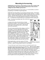
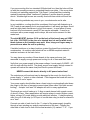
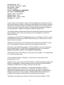
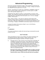
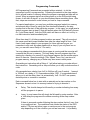
Looking at the board you’ll notice that not all part
positions are occupied. This is normal since the same
board is also used for other models. There are also
some labels on the board that are for other models
(these are noted below).
The top 8 screw terminals are the outputs, you will see
the numbers 1-8 to their right and the LEDs (small
rectangular parts) that go with them to the right of the
numbers. Continuing down the terminals we have the
GROUND connection, 9-24VDC power input, TXD,
RXD, COMMON, RTS, and CTS. The lower 7 screw
terminals have their function written on the back of the
board as a reminder. The screwdriver supplied with the
board may be used to tighten these terminals if you
don't make them too tight, it's only intended for use with
the potentiometer. Another key is the power comes in
next to the yellow disk with two wires, that is the fuse.
On the upper-right you can see a group of 10 holes
labeled J3. The lower two (one square and one round pad) are used to reset the
baud rate. See the Communications section for more details.
To mount the board, use #6 (4mm) screws (not included) through the two
mounting holes (the large holes at the top and bottom). Never screw the board
directly to a flat surface without spacers, the components and protrusions on
the back of the board will cause it to warp, breaking connections on the board. It
will also short out if the surface is metal. Each end of the board is clear of
components and conductors so you may use metal or non-metal spacers or even
a short stack of washers within that area. Make sure no bare wires or other
metal will touch or fall on any other part of the board when the power is on. If
you have any specialized mounting requirements, please contact us. We can
provide spacers and mounting hardware for a wide variety of needs.
5
If you are mounting this to a standard USA electrical box, then the holes will line
up with the mounting screws on a standard blank cover plate. If the cover plate
is metal, put insulating material like “Fish Paper” (vulcanized fiber insulating
material sometimes called “Leatheroid”) between it and the board to prevent
shorts. Weather-tight covers are normally lined with foam which will work fine.
Other mounting methods may occur to you, use what works and is safe.
In any installation, cooling should be considered; this board will dissipate up to
2W if used at max capacity but in most applications it will barely get warm. Avoid
small air-tight plastic enclosures in a hot environment. In rare cases of heavy
load and a hot environment a small DC fan may be advisable. If used in an
enclosure with a power supply and/or relays, be sure to also account for their
waste heat.
The eight MOSFET devices (Q1-8 on the back of the board) may get VERY
hot (over 150C/302F) in the case of a shorted load, do not let wires touch
these devices as the insulation may melt. Also, keep your fingers away to
prevent burns when the unit is operating.
If installed outdoors or in damp locations, protect the board from moisture and
condensation. An outdoor rated electrical box or NEMA compliant water/oilresistant enclosure is the best choice.
You may place any number of these boards in the same enclosure; just
remember to supply enough power and cooling for all of them and their loads.
Verify that your power supply is the proper voltage, it must supply 9-24VDC. AC
will not work with this device. The power source must supply enough current to
operate all loads at the same time plus 50mA to power this board.
NEVER connect this device directly to AC power/mains lines!
The outputs are not fused and may be damaged in the event of a short to the
power supply “+” output or other overload. If this happens the board will need to
be returned to us for repair.
Your power supply should either have a fused output or automatically shut down
the output in the case of excessive current draw (often called “fold back current
limiting”). A simple “wall wart” AC adapter will work in many applications.
This board can control loads up to ¼ Amp on each channel with a peak current
of about 0.4 Amp. Many applications will require relays to control higher current,
higher voltage, AC power, and/or provide electrical isolation. If relays are being
used, the coil of the relay (or DC input of a solid state relay) is what is referred to
as a “load”.
Connect one side of each load to the “+” output of the power supply (possibly
through a fuse) minding any polarity requirements of the load. Connect the
other side of each load to one of the screw terminals (J1) marked “1”-“8”. If you
6
don’t need all eight channels, simply leave the unused ones unconnected.
Run another wire from the “+” output of the supply to the “9-24VDC” terminal on
J1. The supply will now power the loads and the processor on the board.
Using appropriate wire, connect the ground (“GND”) terminal on J1 to the “-“
output of the power supply. This connection is used as ground for all 8 outputs
and the board power, so it should be sized appropriately.
If your loads require over 24VDC, high current, AC power, or isolation, then the
outputs should be connected to relays (either mechanical or solid state) and a
small regulator or separate power supply used to power the board and relays.
Solid state relays draw up to about 50mA each depending on voltage and brand
so a 9-12VDC power supply that can supply ½ Amp or more will be adequate.
If you're using the RS-232 cable supplied with the board, refer to the label
attached to it for wire color codes as these may vary with the brand of
cable we ship. Unused wires should be cut off and taped/covered so they
can't short to anything.
The RS-232 connections are marked on the back of the board, they are the
lower 5 screw terminals. Note that RS-232 COM is connected to the board
ground, it is not isolated. If your host/controller doesn't support RTS/CTS
handshaking, then leave these terminals open. If you're using CTS or RXD as
inputs to your program, you will later need to connect these pins to your
switches. If the Sequencer handshaking is set to ON, then CTS MUST be pulled
high by either the host or by being tied to the RTS pin in order for the host
computer to set up the board. Handshaking is set to OFF as a default so that
either 3-wire or 5-wire connections can be used for initial setup.
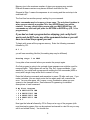
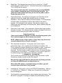
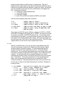
If your computer doesn't have an RS-232 connection
you can purchase a low cost USB to RS-232 adapter
from any store that sells computer supplies, we can
also supply these on special order. A typical one will
look something like this and normally cost about $5.
Most work with Windows, OS X, and Linux. Often no
disk is needed as your computer will recognize it automatically.
The RS-232 connections RXD and CTS may also be used for switch or logic
inputs in advanced programs (see the advanced programming section below).
Note: When the board is powered up, one or more of the outputs may
momentarily flash on. Please make sure this will not cause any problems
with whatever is being controlled.
7
Status Indicators
There are 9 status indicator LEDs on the board. The top center one is used to
indicate board status.
• Steady On: The program is stopped, temperature is normal.
• Slow Blinking (½ second on, ½ second off): The program is running,
temperature is normal.
• Medium Blinking (¼ second on, ¼ second off): Firmware Update in
progress
• Momentary Flicker: RS-232 data received.
• Continuous Flicker: Over-temperature, outputs are disabled and program
stopped.
• Alternating (½ second on, ½ second flickering): Error in program or RS232 command.
• Off: Board power off.
The remaining eight LEDs show the current status of the outputs. They are to
the right of the output numbers close to the screw terminals and show if the
output has been commanded to be on. They will not indicate if there is a fault in
the load (open/short).
8
Basic Programming
For many applications, you will never need more than basic programming. We'll
write and test a sample program that will show you all of the basic features.
First connect the Sequencer board to your computer via an RS-232 cable. You
may want to leave the loads disconnected while you are running sample
programs, as long as you can see the LEDs, you'll be able to tell what's
happening. Apply DC power to the board, there may be a test program loaded
that may start executing.
Make sure all the DIP switches are in the OFF position; it should be marked on
the switch housing but in any case is to the RIGHT. Any test program that was
running will halt and all outputs should now be off.
Open your terminal emulation program (Cool Term is available free from our
website if you don't already have a program), find which communications (COM)
port is associated with the Sequencer, and set the port parameters to:
• 9600 baud or bits per second (factory default rate)
• no parity
• 8 data bits
• hardware (RTS/CTS) handshaking for 5-wire connections
• NO handshaking for 3-wire connections
• “handle backspace” enabled, if there is an option for it
• Echo OFF
If the board has been previously used, the baud rate may have been changed.
See the Communications section for information on how reset it.
If you need any assistance with this, feel free to contact us. We can normally
get you set up and running over the telephone or by e-mail in a short period of
time. There is no charge for this.
Now that you have the terminal program connected to the Sequencer, press the
RETURN or ENTER key on your keyboard (we'll call this CR). You should see a
prompt appear on your screen, it should look like this:
>
If you don't see this, check your terminal program settings and cable
connections. Also, the Power/Status LED should flicker every time you type any
characters or press RETURN.
Now type the letter i and press CR. You should see several lines of information
printed out followed by another prompt. Something like:
Sequencer 8CH copyright 2013 Durand Interstellar, Inc. Version: 20131121 Serial Number: 2013101442
9
Handshaking: OFF
Alternate Line End: 0x00
Baud Rate: 9600
Program Title: Force: 0b00000000 0b00000000
Switches: 0b0000000000 Speed: 105% variable Temperature: 26C Memory Size: 4089 steps Stopped at step 1 > Version refers to the firmware version, we may change the firmware from time to
time to add features, fix bugs, or add some customization for a specific customer.
Normally you would never need to update your firmware, but if for some reason
you do, then contact us for the update. We may also post firmware updates on
our Support page. Updates for standard models are always free.
The serial number contains the date when the board was last tested and locked
before shipping. This is often the same day as it was shipped to assist with
warranty tracking.
Handshaking is the RTS/CTS handshaking status. The default is OFF for 3-wire
connections (but will also work with 5-wire connections). Only turn this on if you
have a 5-wire connection.
Alternate Line End allows use of characters other than Carriage Return for line
ends. Most people will never use this and it can safely be left at zero.
Baud Rate is the RS-232 port speed. Default is 9600 but you may change this
to any speed from 75 to 115200 that is compatible with your host computer.
Higher speeds WILL need to use hardware handshaking.
The Program Title is a text string you have given your program. It is optional and
is for your information only.
Force is a debug feature; it allows you to force one or more outputs to be
permanently on or off.
Switches is the current state of the DIP switches. The left-most binary digits (see
below for a description of binary numbers) are the RUN and PAUSE switches,
followed by FORCE bits 8-1 with bit 1 being on the far right.
Speed is slightly more complicated. In most program steps you will be
specifying a delay time (time to hold on that step). The time you specify is
adjusted by the Speed amount so you may run slightly faster or slower without
having to re-enter your entire program. Variable means the potentiometer is
enabled, Fixed means a number has been manually set and saved.
Temperature is measured on the back of the boar under the Channel 1 LED.
10
Memory size is the maximum number of steps your program may contain.
Different firmware versions may have a different size listed for this.
Stopped at Step 1 means the sequencer is not running and the next step to be
executed is #1.
The final line has another prompt, waiting for your command.
Note: commands may be in upper or lower case. The only time it matters is
when you are entering a program Title, then UPPER/lower case will be
retained. You may correct typing errors with your BACKSPACE key. All
commands are held until you press the RETURN or ENTER key (CR, '\r' for
programmers).
If you had us load a program before shipping, just verify that it
works and do NOT enter any of the commands below or you will
have to re-load the program yourself.
To begin with, erase all the program memory. Enter the following command
followed by CR:
E 1 1
you will see something like this (the ending step may be different)
Erasing steps 1 to 4089
It may take a few seconds before you receive the prompt again.
Our first program is going to be a simple chase sequence as might be used for
marquee lights. The program will use the Title, Set, Jump commands. If you
wanted to, you could have a program with nothing but Set commands (4000 or
more) with a single Jump at the end to cause it to loop.
Enter the following commands and remember to press CR after each one. If you
make a mistake, you can simply enter the line again and it will overwrite the
error. You may use space, tab, comma, or any combination where you see
spaces in the example below. See Advanced Programming for detailed
descriptions of each command.
T My First Program
* 1 S 0b11101110 100
* 2 S 0b11011101 100
* 3 S 0b10111011 100
* 4 S 0b01110111 100
* 5 J 1
Now type the letter D followed by CR to Dump out a copy of the program (with
most terminal programs, this can be captured and saved to a text file so you may
edit it and reload it later). You should see:
11
> D ' Sequencer 8CH ' Durand Interstellar, Inc. ' version 20131113 T My First Program * 1 S 0b11101110 100 * 2 S 0b11011101 100 * 3 S 0b10111011 100 * 4 S 0b01110111 100 * 5 J 1 0x00 ' #### Done > If you see any errors, go ahead and correct them by reentering the line that has
an error. Error example:
* 2 S 0b11111101 100
Just retype the line to fix it:
* 2 S 0b11011101 100
And use the D command again to check everything.
What we've told it to do is set the Title of the program to “My First Program”, then
we stored a series of Set commands in steps 1-4.
The “*” at the beginning of every line tells the Sequencer this is a program step
to be stored in memory.
The first number is the step number that is to be stored.
The “S” is the Set command.
The funny number starting with “0b” is a binary number representing the 8
outputs. The first digit after the “b” is output #8, a “1” means ON. The other 7
outputs follow with #1 to the far right.
The last number on the line is how long to hold this pattern before advancing to
the next step. In this case we are telling it to hold for 100mS (0.100 second).
ALL times are in mS, simply multiply the delay you want in seconds by
1000 and you've got it. The shortest delay you can specify is 1mS, the
longest is about 2 billion mS (over 3 weeks!). One minute is 60 seconds so
that would be 60000mS. One hour is 3600 seconds = 3600000mS.
The final command was “J 1” stored in step #5. This causes the program to jump
back to step #1.
12
Note a Jump takes 1mS, so if you are really picky about timing, then step #4
should have a 99mS delay instead of 100.
The Jump command was displayed with something odd looking at the end,
“0x00”. This number is used for special jumps and most people will never use it.
When entering the program step you may include it or leave it out; it's no
problem either way.
The lines that start with a single quote ' are just information lines for things of
note. A comment may appear anywhere in a line including after a command (but
never before a command). Everything to the right of the single quote will be
ignored by the Sequencer and will NOT be stored with the program. Just be
sure the entire line is 250 characters or less in length. Remember, comments
will only appear in your original file, they are discarded by the Sequencer.
Type R (followed by CR/RETURN) to Run the program and all 9 LEDs should
now be blinking. Try changing the speed by turning the potentiometer (R8,
directly above the DIP switches, labeled PWM RATE) using the included
screwdriver. It will NOT turn all the way around, do not force it. This will allow
you to change the speed from ½ of what you programmed in to twice. If you
need precise speed settings, you may disable the potentiometer with the
command:
V 100 ' this is an example of a comment after a command
This sets the speed to 100% and ignores the potentiometer. This command will
fix the speed at anything from 1% to 255% of the programmed speed. Entering
V with either a zero or no number following it enables the potentiometer to
change the speed. The i (Information) command will tell you what the current
speed is (“variable” means the potentiometer is enabled).
If this is all you needed your program to do, you'd be done.
One other handy feature, you can change the program WHILE IT'S RUNNING!
While your lights are blinking, type the following (the steps are out of order for a
reason):
* 6 J 1
* 5 D 1000
D
Press RETURN after entering step 5 and you'll see a change to the blinking.
The D simply shows you the new program. So, what did this do? Step #6 is a
duplicate Jump to step 1. If step 5 is replaced first, then the program will hit
blank memory and stop. The new Step 5 is a Delay for 1000mS (1 second)
without doing anything else. All the outputs will stay just like they are while the
timer runs out. Let's change step 5 again...
13
* 5 s 0b11111111 1234
D
You'll see it's now turning all the outputs on for 1.234 second after the last
channel chases. Note that the binary number 0b11111111 = 255 = 0xFF, any
version of the number may be used.
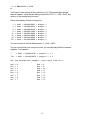
Some other handy number conversions:
1 = 0x01 = 0b00000001 = Output 1
2 = 0x02 = 0b00000010 = Output 2
4 = 0x04 = 0b00000100 = Output 3
8 = 0x08 = 0b00001000 = Output 4
16 = 0x10 = 0b00010000 = Output 5
32 = 0x20 = 0b00100000 = Output 6
64 = 0x40 = 0b01000000 = Output 7
128 = 0x80 = 0b10000000 = Output 8
You do not need to include leading zeros, 2 = 0x2 = 0b10.
To turn on more than one output at a time, you would simply add the numbers
together. For example:
5
130
= 0x05 = 0b00000101 = Outputs 1 & 3
= 0x82 = 0b10000010 = Outputs 2 & 8
For the hexadecimal numbers, they count like this:
0x0 = 0
0x1 = 1
0x2 = 2
0x3 = 3
0x4 = 4
0x5 = 5
0x6 = 6
0x7 = 7
0x8 = 8
0x9 = 9
0xA = 10
0xB = 11
0xC = 12
0xD = 13
0xE = 14
0xF = 15
14
DIP Switches
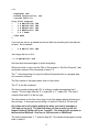
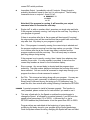
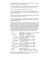
There are labels on the back of the board behind the
switches, these are for a different model of board so
you may safely ignore them.
The picture to the right is a typical switch, the one on
your board may be a different color or style.
Never use a pencil to slide the switch, the point may
break off and fall into the switch.
Start with all the switches turned OFF (to the right), then slide the RUN switch
(top switch, #10) to ON to start your program running (if it isn't already). Leaving
this switch ON starts the program every time the board is powered up. If you
slide it back to OFF, the board will stop and reset the program to step #1 as well
as turning all the outputs off. Switch #10 should be the only one on once you've
completed your installation.
The rest of the switches are optional, they're used to help you set up your
system.
The next switch down from the top (#9) is the PAUSE switch, if the RUN switch is
ON and you slide this switch to ON, the program freezes right where it is. If you
then slide the switch back to OFF without moving the RUN switch, it continues
where it left off.
The bottom eight switches are used to force outputs on so you can check circuits
you may be having a problem with. Switching one of these on overrides
everything except high temperature and turns that output on. Note that switch
#1 is on the bottom while output #1 is at the top. This was done to cause mass
confusion (and to allow this board to be used for other models).
You can override the RUN/STOP/PAUSE state with RS-232 commands but
not the FORCE switches (#1-8).
15
Communications
Some term definitions
Firmware: Control code permanently loaded into the processor on the
board. This may be updated in special cases but is normally never
changed.
Program: User entered commands that are stored in erasable memory
(EEPROM) that controls how the outputs sequence/flash.
RS-232: Standard communications interface that allows computers to talk
to people and other computers.
Host Computer: A PC, industrial controller, HVAC, lighting control, or
some other computer that is capable of sending commands over an RS232 interface.
White Space: Any of several characters that are used to separate portions
of a command. Examples are space, tab, newline, comma, double quote.
As characters come in from the RS-232 interface they pass through a small
buffer. If the characters come in while the firmware is busy, they will be held with
no problem. If the buffer is almost full and handshaking is enabled, the RTS line
is set low/inactive to tell the host computer to pause sending. As soon as the
firmware reads the characters from the buffer the RTS line is returned to
high/active. If handshaking is off, then the RTS line will always be high/active
and any characters that won't fit in the buffer are discarded/lost, it is up to the
HOST computer to not send another command until the previous command has
completed. If entering commands by hand, this isn't a problem. If you copy &
paste or upload programs from a file, then use 5-wire mode with handshaking
ON or set a line-end delay of about 100mS in your terminal program.
Data transfer is full duplex in that received characters are echoed back to the
host/controller as soon as the firmware fetches them from the buffer.
If handshaking is ON and the CTS line is unconnected or inactive (ground or
negative), the Sequencer does NOT send any characters to the host computer.
It stops receiving commands as it waits for permission to send the previous
response. If handshaking is set to OFF or CTS is tied high, then responses are
always sent regardless of if the HOST is ready.
Any White Space received before the first regular character of a command is
discarded. After this all characters (up to about 250) are stored until a
CR/RETURN is received. Corrections are made by using the backspace key
(this will not back over any leading White Space that was discarded). Command
processing starts when a Carriage Return (RETURN, ENTER, CR, or '\r') is
received. There may be any amount/combination of white space between
portions of a command line as long as it all fits in 250 characters. The following
commands are all treated the same:
16
*1 s 5 100
* 1,,,,”””s 5 100
“*”, 1, “S”, 5, 100
Almost all commands may be entered in UPPER or lower case, the only time it
makes any difference is with the Title and UPDATE commands.
There is an optional debug command that sends data to the host that can be
handy for complex programs. Note that if handshaking is ON and CTS is
inactive or open, your program will freeze when using the debug command!
If for some reason you can't use RTS/CTS handshaking (on some computers it
simply isn't there), then set your terminal emulator program to either pause after
sending each line for 100mS or to wait for the next prompt, that would be the
character “>”.
If using end of line delay in CoolTerm you would also have to set the end
of line characters to 0d 0a (zero, D, space, zero, A).
In CoolTerm under Connection Options there's a tick box to enable it to
“handle” the backspace key, that should be turned on. Other terminal
programs may have a similar option.
Notes for people writing code on their host/controller to talk to the Sequencer:
• CR ('\r') is the end of a line, not NL ('\n') unless you've set it as an
alternate line end character.
• Data is echoed as received, you must receive this without setting CTS as
busy. Forgetting to flush a receive buffer is a common error.
• Any characters with errors are discarded and not echoed.
• The prompt is sent as “\r\n> ” but if there is an alert the alert name will
inserted such as “\r\nForcing! > ” (this alert indicates that either a DIP
switch is on or the Force bits are enabled in the settings).
The following section is to be used to reset the the baud rate to 9600 if you
changed it and forgot what you changed it to.
1.
2.
3.
4.
BAUD Reset
Turn off the power to the board.
On the upper right of the board is a group of 10 holes with a box drawn
around them. The bottom two holes have a tiny number 1 and 2 next to
them and there will be an identifier such as “J3”. Short these two holes to
each other with a piece of wire. No need to solder it, just stick it in the
holes being careful to not short to anything else.
Turn on the power to the board and wait until the POWER LED lights.
Remove the wire that was shorting the holes and the BAUD Rate will be
reset to 9600, no handshaking.
17
Saving and Loading Programs
Programs are saved to a text file using your terminal emulator program, the
exact method will vary with the program but generally entails
saving/receiving/logging to a file on the host computer. To save your entire
program type the D command but without pressing RETURN. Then open the file
with your terminal emulator program and press RETURN. The program will be
downloaded and saved to your file. When it completes, close the file (stop
logging, close, save, etc.).
Open it with a text editor like Notepad in Windows or gedit in Linux and make
any required changes to it. Especially check for any extra lines that shouldn't be
there like the very last one or two.
This file may be imported into or created in a spreadsheet. Export it as a CSV
file before uploading it to the Sequencer. The spreadsheet may use space, tab,
comma, and/or double quotes any place white space is expected.
To upload a file open your terminal program and SEND as a text or raw file.
If you have the file open in a text editor, try to “copy all” from the editor and paste
it using the terminal program's PASTE command (probably in the EDIT menu).
This may not work with a terminal programs.
Some computers will store text files with New Lines instead of Carriage
returns at the end of every line. These text files can only be sent to the
Sequencer if you set the Alternate Line End character to 0x0A (NL).
18
Advanced Programming
Here every command is described in detail. When numbers are used they may
be in any combination of decimal, hexadecimal, or binary. Leading zeros may be
left off EXCEPT the zero before an x, X, b or B.
Decimal: Normal base-10 numbers from -200000000 to 200000000 (negative 2
billion to positive 2 billion) with no decimal point, commas, spaces, or prefix
(other than a possible negative sign '-').
Hexadecimal (Hex): Base-16 numbers, it is often handier to use this for some
numbers. Hex numbers are always preceded with 0x or 0X and consist of one to
8 digits after the X. Each digit is from the set [0-9, A, B, C, D, E, F]. Example:
0x19AC = 6572 decimal.
Binary: Base-2 numbers. Very handy for setting the outputs with the Set
command. Binary number are always preceded with a 0b or 0B and up to 32
binary digits. Each digit is either a zero or a one with the least significant (output
#1) to the right. Example: 0b10000010 would indicate outputs # 2 and 8 are on.
Leaving off a number is the same as setting it to zero, so the following
commands are all the same:
V 0
V
V 0x00000000
A command expecting two numbers but only receiving one assumes the second
number to be zero.
Host Commands
These commands are not part of your program, they retrieve information from
the Sequencer and also change settings. Typing a question mark ? and
pressing RETURN will display a reminder list of these commands.
A
Alternate Line End. Most computers use Carriage Return (RETURN, CR
or ENTER) to signal the end of a line. Some computers may use New
Line instead, especially for sending files stored on your disk. Setting this
option to something other than zero allows use of these alternate
characters. The most common settings will be 0x00 (off) or 0x0A (NL). If
you're using a programmable logic controller (PLC) or lighting control, you
may find it handy to use some other character entirely for line end to
make your programming easier.
Note that Carriage Return (CR) is ALWAYS valid, the above command
just adds a second additional character. If you sent both CR and NL
then this will be seen as TWO lines with one blank (not a problem).
19
B
Baud Rate. This changes the speed of the host serial port. It MUST
match what your system requires. The speed may be set to anything from
75 to 115200 bits per second.
The new speed will take effect immediately after pressing RETURN
so you need to change the speed in your terminal program. The
speed will remain set the next time you turn on the power so don't
forget what you set it to.
D
Display/Download. This displays the program in a format that can be
captured to a text file, edited, and reloaded into this or another
Sequencer. A D by itself will display the entire program. If it's followed by
a single number it will display from that step number to the end of
memory. If it's followed by two numbers, then the first number is the
starting step and the second is the ending step. Blank (erased) steps will
not be displayed.
E
Erase one or more steps. If the command is followed by a single number,
that step is erased. If it's followed by two numbers, all steps from the first
number to and including the last number are erased.
Erase Special Case
If the second number is negative, all steps from the step given by the
first number through the end of memory are erased.
NOTE: When erasing a large number of steps there may be several
seconds delay before you receive a prompt.
F
This sets/clears forcing bits. Forcing sets one or more outputs
permanently high or low, normally used for testing your system. The
Force command is always followed by two numbers or none. If there are
no numbers following the F, the outputs go back to normal (forcing
removed). The first number is which outputs to force, the second number
is what levels to force them to. For example, to force output 3 high and 1
low while leaving all the others alone, issue this command:
F 0b00000101 0b00000100
The Force bits are stored with the program so they will remain in effect
through any number of power cycles until cleared.
Note that the lower 8 DIP switches will override any forcing you have
set, they will ALWAYS cause an output to turn on.
When either DIP switch or command forcing is in effect, you will
receive an alert to the left of every prompt.
H
Handshaking. Setting this to 0 turns off RTS/CTS handshaking. Setting it
to 1 will turn it on. Default is 0. Make sure a 5-wire host is connected
before enabling this.
I
The Information command displays various details about the system. This
will show if a program is running or stopped, the speed setting, and the
20
current DIP switch positions.
O
Immediate Output. Immediately sets all 8 outputs. Binary format is
probably the easiest format to use, but it is not required. The following
commands turns on outputs 1-4 and 5-8 off:
O 0b00001111
O 0x0F
O 15
Note that if the program is running, it will override your output
command when it executes the next step.
P
Single steP. P with no number after it executes one single step and halts.
If the program is already running, it will stop at the next step. Any delay in
your program is ignored.
If there is a number after the P, the program will be stopped (if running),
the step number given will be executed and the program halts on the next
step after that. Any delay in your program is ignored.
R
Run. If the program is currently running, the current step is aborted and
the program continues running from the step number you provide. If there
is no number after the R, the current step delay is aborted and the
program continues with the next step. This is a handy way to advance
past long delays during testing.
If the program is not currently running, then it starts from whatever step
number you provide. If no step number is provided, it starts from the
current step number as shown in the Information display.
S
Stop or pause. Any current delay is aborted and the program stops
executing. The step number displayed indicates the next step that would
have executed. You can use the P command to single step through your
program from here or the R command to restart it.
T
Set Title. This stores a text string along with your program. You may use
it in any way you wish, commonly to indicate your program version.
Simply enter T followed by any text string up to 30 characters long. To
erase the title, then enter T with nothing following it besides the RETURN.
UPDATE A special command to install a firmware upgrade. This function is
rarely needed, please contact us for instructions if you need to use it.
V
This sets a fixed ratio for the Speed or enables the potentiometer to
change the Speed. V followed by a number between 1 and 255 sets the
speed to that percentage (1% to 255%). V followed by 0 or just a
RETURN enables the potentiometer to set the speed from 50% to 200%.
Program delays are calculated at the beginning of every step by
multiplying the delay stored in your program by the Speed percentage.
Once a step has entered its delay, changing the Speed will have no effect
21
until the next step has started.
Be careful setting very low percentages, at 1% Speed a one second
delay (1000mS) becomes a 100 second delay!
*
This causes the following command line to be stored as a program step.
Every program line starts with an *.
>
Insert/delete steps. This allows you to insert any number of blank steps in
front of any other step in your program. You may also delete any number
of steps starting at the given location. This operation may take several
seconds depending on how much has to be moved. Examples:
> 10 5
This will move step 10 and all those above it up by 5 and insert 5 blank
steps in locations 10-14. Step 10 will be come step 15, step 11 will
become 16, etc. If your program went all the way to the end of memory
the top 5 steps will be lost.
> 10 5
This will delete steps 10 through 14 (5 total). Step 15 will be moved to
step 10, step 16 will become step 11, etc. If your program went all the
way to the end of memory there will now be 5 blank steps there.
Note: When inserting/deleting steps all jumps will be adjusted to
point to the new locations BUT if a jump had pointed to a step that
has been deleted or fallen off the top of memory during an insert,
then that jump will be broken. You will have to inspect your jumps
to make sure none broke during this operation.
'
Comment. This may appear anywhere on a line, including after a
command. This character and anything to its right will be ignored
completely other than it counts towards the 250 maximum characters you
may send in a single line. Your comment will NOT be stored, it is for your
notes only.
?
Prints out a list of all of the above commands.
22
Programming Commands
All Programming Commands are preceded with an asterisk * to let the
sequencer know it's a program step. Following the asterisk is the step number,
this is a fixed location in memory where the program command and data will be
stored. When a program starts from either power up or the RUN switch being
thrown, it will start at step #1 so you should always have something there. After
that, steps are executed in order unless you have a Jump command.
For special applications, you may have multiple programs loaded into memory
and execute any of them by using the Run command followed by the step
number that is the start of that particular program. In this case, you might want a
default program start at step #1 that will execute when the RUN switch is thrown.
Or, if you Erase step #1, then the RUN switch will have no effect as it will try to
run that instruction and immediately halt.
Other than step #1, all other program locations are equal. They all execute at
the same speed and jumps between them take the same length of time. Feel
free to leave spare space in your program for future edits as long as you
remember to skip over this spare space with a Jump (if you only have one or
two, you can also use a Delay of 1 for each).
You may change commands while the program is running and the new step will
overwrite the old one in memory. This may delay the next program step from
starting by a fraction of a second if your change happens just as another step is
about to execute. Since the settings (Title, Speed, Force, etc.) are stored in
program memory, changing any of these may also cause a short pause.
Overwriting an instruction with a Delay of 1 will allow testing your code without
that instruction. Overwriting with a Jump will allow you to skip a whole section of
code.
All commands have a delay from 1mS to 2 billion mS (over 3 weeks). 1 second
is 1000mS, so a delay of 1-1/4 seconds would be 1250. If a command doesn't
allow you to set the delay, then it is automatically 1mS. Do NOT use spaces,
decimal points or commas in a number.
Each command below has to start with an asterisk and a step number so the
Sequencer knows to store it in memory instead of trying to execute it.
D
Delay. This should always be followed by a number indicating how many
mS the program is to pause.
J
Jump. In most cases this will simply be followed by a step number. After
a 1mS delay the program will continue executing at the step number
given.
If there is a second number following the step number that isn't zero, that
is a conditional test. The conditional test checks the status of the RXD
and/or CTS pins and either jumps or continues on to the next program
step depending on if the condition you set has been met. It is probably
23
easiest to deal with the condition setup in hexadecimal. The left or
highest four bits select which of the inputs will be tested while the right or
lowest four bits select what the data has to match for a jump. As we have
only two possible inputs, there are four possibilities for the highest four
bits. In hex these would be:
• 0: neither bit is tested (always jump)
• 1: only CTS is tested
• 2: only RXD is tested
• 3: both CTS and RXD are tested and BOTH must match
Here are some example jumps with comments:
*J 4 *J 4 0
*J 5 0x10
*J 1234 0x22
*J 1 0x33
' always jump to step 4
' always jump to step 4 (alternate)
' jump to step 5 only if CTS is LOW
' jump to step 1234 only if RXD is high
' jump to step 1 only if BOTH RXD and ' CTS are high
Since these are RS-232 inputs, HIGH is a voltage of +3VDC to +25VDC
and LOW is a voltage from ground (0V) to -25VDC. An open pin is pulled
to ground by a resistor in the RS-232 receive chip. To use these inputs
for switching your program, you would connect a switch from either one or
both inputs to a source of positive DC voltage. Any logic device that can
drive the input over 3VDC with a 3kΩ load will also work. The RTS output
supplies about 6V and can be used to power these inputs.
L & N
Start a Loop & Next loop. Let's say you have a sign where every few
seconds a sequence of lights are to chase across the bottom, maybe
arrows pointing to the store entrance. It's been determined that the
arrows should cycle 5 times and then go out for 10 seconds before
starting over. You could enter the program where you simply enter it as a
long series of steps but that could be a lot typing. This is where the loop
comes in. A loop starts with the L command followed by a number
indicating the number of times it should go through the loop (any number
from 1 to 2 billion). The L step executes once to set up the loop and
takes 1mS, the program then continues on as normal until a Next
command comes up. The N decrements the loop count by one and if it's
not zero yet, it Jumps to the step following the L command. Example of
looping 5 times:
* 1 S 0 10000
* 2 L 5
* 3 S 1 100
* 4 S 2 100
* 5 S 4 100
* 6 N
* 7 J 1
' turn off all outputs for 10 seconds
' start a loop, execute it 5 times
' turn on output 1 for 100mS
' turn off 1, turn on 2 for 100mS
' turn off 2, turn on 3 for 100mS
' Next loop, count – 1, jump to step 2
' jump back to step 1
24
The indented lines are just to make it easier to follow, there's no need to
indent lines when you're entering a program.
In the above example step 1 executes, waits 10 seconds, then continues
on to step 2 which sets up a loop and then continues on to step 3.
Steps 3-5 execute as normal and then we get to step 6.
The N command subtracts one from the loop count that was set up in
step 2. If count is still above zero, then the program jumps back to step 3
(the step AFTER the L).
When the count is finally zero, the program continues on to step 7 which
simply jumps back to step 1 to start over.
The above program can be very useful, but sometimes you might want to
have a loop inside of a loop. Never fear, you can “nest” loops up to 4
deep (inside each other).
Before viewing the steps, you should understand what a Stack is. Think
of this as a stack of notes in a small box. You can only see the top note
and you may add a note by placing it on top of the stack or delete one by
removing it from the top. You may also change the information on the top
note. We call adding a note PUSHING and removing a note POPPING.
There's one additional limitation, if you PUSH a fifth note on top of the
stack, the bottom note disappears so there is never more than 4 notes in
the stack. This stack is used to keep track of the loop count and the
starting step for the loop. Indented lines to make it easier to follow.
* 1 L 5
' PUSH count (5) & start (2) for loop A
* 2 L 3
' PUSH loop B (inside of A)
* 3 L 100
' PUSH loop C (inside of A, B)
* 4 L 6
' PUSH loop D (inside of A, B, C)
* 5 S 0b1 55 ' turn on output 1 for 55mS
* 6 S 0 1 ' all outputs off
* 7 N
' Next D, jump to step 5 or POP
* 8 S 0b10 12 ' turn on output 2 for 12 mS
* 9 S 0 1
' all outputs off
* 10 N
' Next C, jump to step 4 or POP
* 11 S 0b100 100 ' turn on output 3 for 100mS
* 12 S 0 1 ' all outputs off
* 13 N ' Next B, jump to step 3 or POP
* 14 S 0b1000 10 ' turn on output 4 for 10mS
* 15 S 0 1
' all outputs off
* 16 N
' Next A, jump to step 2 or POP
* 17 J 1
' always jump back to step 1 for more
Step 1 starts loop A by writing the address of the next step (2) and the
count (5) on a note and PUSHING it on the stack.
25
Step 2 starts loop B, the PUSH here will place the note for loop B on top
of the note for loop A so now all we see is the loop B note.
Step 3 PUSH the loop C note on top of the note for loop B.
Step 4 PUSH the loop D note on top of the note for loop C.
The above steps will re-create their note every time they're
executed, so for every pass through loop C the loop D note will be
re-created and loop D will run for 6 additional loops.
Steps 5 & 6 blink output 1.
Step 7 decrements the loop count on the top note (D) and if not zero jump
to the step on the note (step 5, the step AFTER the L command). If, after
the decrement, the count is zero, discard (POP) the note on top (D)
revealing the note for loop C and continue on to step 8.
Steps 8 & 9 blink output 2.
Step 10 decrements the loop count on the top note (C) and if not zero
jump to the step on the note (step 4, the step AFTER the L command). If,
after the decrement, the count is zero, discard (POP) the note on top (C)
revealing the note for loop B and continue on to step 11.
Steps 11 & 12 blink output 3.
Step 13 decrements the loop count on the top note (B) and if not zero
jump to the step on the note (step 3, the step AFTER the L command). If,
after the decrement, the count is zero, discard (POP) the note on top (B)
revealing the note for loop B and continue on to step 14.
Steps 14 & 15 will blink output 4.
Step 16 decrements the loop count on the top note (A) and if not zero
jump to the step on the note (step 2, the step AFTER the L command). If,
after the decrement, the count is zero, discard (POP) the note on top (A)
leaving the box empty and continue on to step 17.
Step 17 will always jump back to step #1 to start things all over again.
When you get to step #17 the innermost loop D will have executed 9000
times! Loop C will have executed 1500 times, loop B 15 times, and loop A
5 times.
If you try to nest 5 loops deep, then the note for loop A will be lost. When
the Next is executed for loop A it finds an empty stack and simply
continues on as if there was no loop. The same thing will happen if you
have more Next commands than you have Loop commands. An empty
stack causes the Next command to be ignored.
26
P
Pause or stoP. The program stops running leaving the outputs in
whatever state they were last set to.
S
Set the output state. This will be the most used command in your
program. The Set command is always followed by two numbers, the
output data and the delay time (how much time passes before the next
instruction is executed). Every Set command affects all outputs, so if an
output was on and you want it to stay on, be sure to set it to a '1' in the
next Set command. For example:
* 1 S 0b00000011 100
* 2 S 0b01000011 200
* 3 S 0b01000010 1100
!
' set outputs 1 & 2 on
' all others off,
' delay for 0.1 second
' set output 7 on
' leave 1 & 2 on,
' delay for 0.2 second
' set output 1 off
' leave 2 & 7 on,
' delay for 1.1 seconds
Debug. This sends debugging information to the host computer when this
step is executed. The length of time taken by this step will vary with the
number of characters that need to display, the status of the CTS pin if
handshaking is enabled, and if there's any pending display from a host
command. If handshaking is enabled and CTS is inactive, your
program will hang on this step.
For example:
* 5 !
displays the following if it is not in a loop
Debug at step 5
If the debug statement is inside a loop, then you'll receive additional
information such as:
Debug at step 5 Loop Count 4 Loop Start 2
This tells you that the program executed step 5 while inside a loop and
the current loop count is 4. The loop start is where the Next will jump to
when it executes. You would normally expect to see 3 more of these
counting down to 1 before the Next did not perform the jump and the
program continued.
27
California Proposition 65 Warning
The following information is required by the State of California's Safe Drinking
Water and Toxic Enforcement Act of 1986 (Proposition 65). This California
regulation does not address safe levels; therefore, even trace amounts of the
chemicals included on Proposition 65's list of chemicals known to the State of
California to cause cancer or reproductive toxicity must be noted.
WARNING: This product contains lead and/or other chemicals
known to the State of California to cause cancer and/or birth
defects and/or other reproductive harm.
FCC Statement
This device complies with part 15 of the FCC Rules, Class A.
Operation is subject to the following conditions:
1. This Device may not cause harmful interference, and
2. This Device must accept any interference received, including interference
that may cause undesired operation.
Open Source Software
This device uses Open Source code from FreeRTOS.org which is licensed under
the modified GNU General Public License (GPL). The FreeRTOS source code
and license file are available at www.freertos.org or you may contact us for a
copy at no charge.
Tech note
This board uses an ARM processor running at 48MHz and has 32K bytes of
EEPROM. The firmware is written in C and assembly language and uses the
FreeRTOS operating system. It is available customized in various ways
(more/less memory, custom or no firmware, isolated RS-485/MODBUS/DMX
interface, I2C interface, PWM dimming outputs, etc.) by special order.
28
Warranty
Durand Interstellar, Inc. warrants this product to be free from manufacturing defects in
original material, including original parts, and workmanship under normal use and
conditions (“manufacturing defect”) for a period of one (1) year from date of original
purchase. A charge will be made for repairs not covered by the warranty.
Should service become necessary, contact Durand Interstellar, Inc. for return
authorization and then:
•
•
•
Pack the unit in a well-padded corrugated box
Enclose a copy of your proof of purchase, if you are not the original
purchaser
Ship the unit prepaid via an insured carrier
NOTE: This warranty is void if the product is:
•
•
•
•
Damaged through negligence, misuse, abuse, or accident
Modified or repaired by anyone other than Durand Interstellar, Inc.
Damaged because it is improperly connected to other equipment
Damaged by any power source that does not meet stated specifications
NOTE: This warranty does not cover:
•
•
•
•
•
•
Damage to equipment connected to the product
Cost incurred in the shipping of the product to Durand Interstellar, Inc.
International shipping costs.
Damage or improper operation of unit caused by customer abuse, misuse,
negligence, or failure to follow operating instructions provided with the
product
Ordinary adjustments to the product which can be performed by the
customer as outlined in the instruction manual
Improper operation of the unit caused by software written by any third
party
ANY APPLICABLE IMPLIED WARRANTIES, INCLUDING THE WARRANTY OF
MERCHANTABILITY, ARE LIMITED IN DURATION TO THE PERIOD OF THE
EXPRESSED WARRANTY AS PROVIDED HEREIN BEGINNING WITH THE DATE OF
ORIGINAL PURCHASE AT RETAIL, AND NO WARRANTIES, WHETHER EXPRESS
OR IMPLIED, SHALL APPLY TO THE PRODUCT THEREAFTER. DURAND
INTERSTELLAR, INC. MAKES NO WARRANTY AS TO THE FITNESS OF THE
PRODUCT FOR ANY PARTICULAR PURPOSE OR USE.
UNDER NO CIRCUMSTANCES SHALL DURAND INTERSTELLAR, INC. BE LIABLE
FOR ANY LOSS, DIRECT, INDIRECT, INCIDENTAL, SPECIAL, CONSEQUENTIAL
DAMAGE, OR PATENT ISSUES ARISING OUT OF OR IN CONNECTION WITH THE
USE OF THIS PRODUCT.
THIS WARRANTY IS ONLY VALID IN THE UNITED STATES OF AMERICA. THIS
WARRANTY GIVES YOU SPECIFIC LEGAL RIGHTS. HOWEVER, YOU MAY HAVE
OTHER RIGHTS WHICH MAY VARY FROM STATE TO STATE. SOME STATES DO
NOT ALLOW LIMITATION ON IMPLIED WARRANTIES OR EXCLUSION OF
CONSEQUENTIAL DAMAGE, THEREFORE THESE RESTRICTIONS MAY NOT APPLY
TO YOU.
29