1
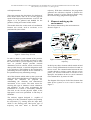
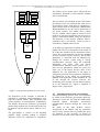
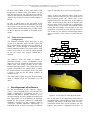
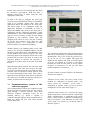
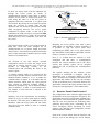
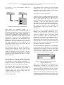
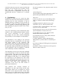
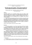
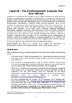
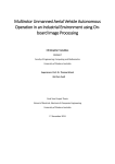
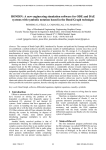
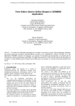
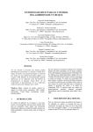
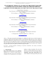
2005 WSEAS/IASME Int. Conf. on ELECTROSCIENCE and TECHNOLOGY for NAVAL ENGINEERING and ALL-ELECTRIC SHIP
Miami, Florida, USA, November 17-19, 2005 (pp23-30)
PLATFORM OF TRIALS IN AN OPEN ENVIRONMENT FOR THE
COOPERATION OF MARINE VEHICLES PROGRAMMED IN
LABVIEW WITH WIRELESS CONNECTIVITY BY MEANS OF WIFI
FRANCISCO J. VELASCO
Dept. Electronics Technology and Systems Engineering and Automatics
Univ. Cantabria.
E.T.S. de Náutica - C/ Gamazo 1- 39004 Santander (Cantabria)
SPAIN
TERESA M. RUEDA
Dept. Electronics Technology and Systems Engineering and Automatics
Univ. Cantabria.
E.T.S. de Náutica - C/ Gamazo 1- 39004 Santander (Cantabria)
SPAIN
ELÍAS REVESTIDO
Dept. Electronics Technology and Systems Engineering and Automatics
Univ. Cantabria.
E.T.S. de Náutica - C/ Gamazo 1- 39004 Santander (Cantabria)
SPAIN
LUIS ÁNGEL ESQUIBEL
Dept. Electronics Technology and Systems Engineering and Automatics.
Univ. León
E. de Ingenierías –Campus de Vegazana, s/n – 24071 León
SPAIN
Absract: - This paper presents the development of a platform for trials on sea vessels for actions in
cooperation, using an in-scale physical model of an autonomous high speed sea vessel, which has
available an Industrial PC which will act as a client by means of a wireless connection to a laptop on
land, where the server application is based. A software support has been implemeneted in LabVIEW
which can capture and store data at a distance of all the platform instruments with wireless connecticity using
wifi. This software accepts the different communication protocols required for the platform and is suitable for
carrying out the Guidance, Navigation and Control of the physical model.
Key Words: - Sensorial integration, monitoring of trajectories, DataSocket, wifi, wireless, environment,
cooperation, marine vehicles.
1
Introduction
One of the research lines of the VAMCoop
DPI2003-09745-C04-03 project is the study of the
manoeuvres of a vessel for actions taken in
cooperation with other vessels, such as assistance to
a damaged vessel, towing manoeuvres, and chinese
landing or sailing in proximity. The aim of the
Project is to design controllers for the control of
these manoeuvres and for the monitoring of planned
trajectories. Tests were also made in an
uncontrolled environment, including trials at sea,
for the validation of the designs made, prior to their
2005 WSEAS/IASME Int. Conf. on ELECTROSCIENCE and TECHNOLOGY for NAVAL ENGINEERING and ALL-ELECTRIC SHIP
Miami, Florida, USA, November 17-19, 2005 (pp23-30)
real implementation.
This paper presents the description of a platform of
trials which allows data on an in-scale physical
model of the high-speed autonomous vessel TF-120
(Figure 1) to be gathered and handled for the
guidance, sailing and control of this model.
This model allows the various tasks of coordination
between two vessels, such as tow-boats, to be
performed for joint actions.
trajectory. With these calculations, the programme
generates the references required to perform the
dynamic control [3] of the physical model, using
the control strategy judged most appropriate.
2
Elements making up the
environment
The elements that make up the environment are
shown in Figure 2.
UM I
Accelerometer
Speed regulator
Engine
GPS
Gyrocompass
D
S
PWM
Servo
Access point
Sea
Figure 1: Turbo Ferry TF-120
In order to obtain a good estimate of the position,
speed, acceleration and heading and thus to make
the vehicle follow a preset trajectory with as little
error as possible despite possible external
disturbances such as currents, winds, swell and any
other posible obstacle, a sensorial integration needs
to be carried out. This platform is also designed for
performing the trials required for the selection of
the optimum trajectory monitoring strategy.
All of the elements which make up the system and
which will be described below are industrial, as for
example the industrial PC prepared for
withstanding the vibrations and characteristic
movements of sea vessels. The main reason for
selecting this type of elements is their robustness
and reliability. In this trials environment, the
installation of a vesssel is successfully emulated.
The trials on the in-scale physical model of the
high-speed vessel were performed in The Bay of
Santander.
The software support designed is capable of
making all of the calculations required for planning
the trajectories [7], starting from the input data,
which is: the starting point, final point, type of
trajectory and time taken to describe each
Access point
Industrial PC
Embarked elements
Earth
Laptop
Figure 2. Elements required for monitoring a
trajectory.
In this layout, those elements which remain on land
can be clearly differentiated from those located on
the sea vessel. The communication between the two
is made through a wireless system with two access
points, one on land connected via wireless to the
laptop PC and another on the sea vessel connected
to the industrial PC by means of cable.
The diagram of the layout of all of the elements that
make up the system on a sea vessel is shown in
Figure 3.
Accelerometer
2005 WSEAS/IASME Int. Conf. on ELECTROSCIENCE and TECHNOLOGY for NAVAL ENGINEERING and ALL-ELECTRIC SHIP
Miami, Florida, USA, November 17-19, 2005 (pp23-30)
Turbojet 1
Engine 1
Serv o 1
12V
12V
12V
Turbojet 2
Engine 2
Serv o 2
12V
12V
12V
IndustrialPC
Antenna
Access
Radiocontrol
Point
Receiv er
U.M.I
The wireless access points can be affected by the
interferences produced by other elements working
in the 2.4 GHz band.
GPS
Electrical
grid
Source
24V
Accelerometer
Gy rocompass
The two motors were mounted at stern. These make
the turbines of the two turbojets that form part of
the propulsion rotate. Each motor is regulated by a
speed variator which is controlled by a PWM (Pulse
Width Modulation). For the correct functioning of
the speed variators and Futaba motor control
servoes, a PWM control signal of around 55.6 Hz
needs to be generated. It has thus been necessary to
design a custom-built PWM, using 555 integrates.
The direction of the turbojet propeller fluid is
controlled with a servomotor, which in turn is
controlled by a PWM control circuit.
A SCADA type application installed in the laptop
handles the on-screen presentation and storage of
all of the data measured by the instruments on the
vessel. The contol parameters can also be modified
in order to monitor a given trajectory. The SCADA
application is connected with the industrial PC
through the wireless system using a TCP/IP
communication protocol, using the LabVIEW
DataSocket tool [4][6]. This tool allows
communication between remote panels, that is,
there are two applications which are exactly the
same: one in the laptop and the other in the
industrial PC. The application of the laptop is
configured so that all of the parameters modified in
the application of the laptop are automatically
updated in the application of the industrial PC, all
of this through the wireless network. The
calculating power and the real time data acquisition
lie in the industrial PC, which is equipped to
support such a requirement.
Figure 3. Layout of the elements on a sea vessel
2.1
The disposition of the elements is intended to
contribute to a balanced weight distribution, apart
from the required ballast. This distribution also
avoids problems of electromagnetic compatibility.
The distance between the electronic gyrocompass
and the other elements, the closest being in this case
the batteries and the electric panel, must be over 1
metre.
The gyrocompass is sensitive to the adjoining
magnetic fields, possibly leading to magnetic
alterations which are impossible to compensate.
Instrumentation in the environment
The current heading, position, time, etc are obtained
by means of the electronic gyrocompass KVH [8].
This data is sent to the PC using the NMEA 0813
(National
Marine
Electronics
Association)
communication protocol through the serial gate
RS232.
By means of the GPS RCB-LJ receiver
incorporated in the TIM-LF chip [9], parameters
such as fairly accurate data on position and speed
are obtained. It was necessary to design an
electronic circuit which could make the conversion
2005 WSEAS/IASME Int. Conf. on ELECTROSCIENCE and TECHNOLOGY for NAVAL ENGINEERING and ALL-ELECTRIC SHIP
Miami, Florida, USA, November 17-19, 2005 (pp23-30)
of levels from CMOS to TTL and which could
incorporate an RS232 serial gate adaptor. In this
way, the GPS receiver can send and receive data by
means of the selected communication protocol. The
TIM-LF chip accepts the protocols UBX, NMEA Y
RTCM.
In order to obtain data on the movement of the
physical model, two triaxial acelerometers are used,
one located at stern and the other at bow. The UMI
(unit of inertial measurement) also provides values
for the six degrees of freedom of movement of the
model.
2.2
types of controllers to be carried out fairly simply.
Figure 4 shows the different control loops of the
system actuators which may be: the control loop of
the propulsion speed, the control loop of the
propulsion direction and the loops of the stabiliser
flaps – the bow flap (T-Foil) shown in Figure 5 and
the stern flaps (Flaps). Each motor is controlled by
a speed variator, a servomotor and a PWM control
circuit, but the analogue control signal of the data
acquisition card can be the same for both motors or
not. In this way, the turbojet rotation angle and the
speed of rotation of the motor are practically the
same.
Manual/automatic/manual
Configuration
The elements described above form part of the
system in its automatic mode, but the system also
has a manual mode, through which it is possible to
handle sea vessels through a commercial radio
control modeling handset. The signal sent by radio
control is received by a a receiver station installed
on the sea vessel. The receiver station has 4
channels.
Pc Industrial
TAD
PWM
PWM
PWM
PWM
Servo
Servo
Speed
regulator
Flaps
PWM
Speed
regulator
Servo
Servo
Engine 1
The crossover from one mode to another is
performed through a series of industrial relays,
which also serve to separate the power part from the
control part. This brings security in the worst
possible operating scenario. The normal state of the
system corresponds to the manual mode, in which
the system remains even when the feed is lost, until
a signal is sent by the PC which switches to
automatic mode.
PWM
Turbojet1
Engine 2
Turbojet2
T-Foil
Figure 4: Propulsion Control
The radio control signal for going from automatic
mode to manual mode has prevalence over all
others.
3
Development of software
For the development of the software support,
version 7.1 by LabVIEW [2][5], was selected as the
graphic programming environment as this is a
Standard and allows graphic interfaces to be
developed simply. It is also suitable for making real
time applications, as it incorporates an operating
system for this purpose called ETS (Embedded
ToolSuite) developed by the company Ardence
Venturcom. Another important characteristic of
LabVIEW is that it allows the testing of different
Figure 5: T-Foil of the in-scale physical model
One of the tasks of the application which falls on
the industrial PC, called Industrial_Client.exe, is the
gathering and storage of the data from all of the
instruments which make up the platform. For this
purpose, the process is equipped with a series of
2005 WSEAS/IASME Int. Conf. on ELECTROSCIENCE and TECHNOLOGY for NAVAL ENGINEERING and ALL-ELECTRIC SHIP
Miami, Florida, USA, November 17-19, 2005 (pp23-30)
threads. One of them is for acquiring the data from
the electronic gyrocompass. With this data, a
heading control loop is made, using the most
appropriate control law.
In order to be able to configure the serial gate
correctly using LabVIEW, the VISA 3.0 installation
needs to be installed. Among other tasks, this
application detects the number of PC serial gates
and allows them to be configured inside the
application designed in LabVIEW. In order to
support the NMEA 0813 protocol, the serial gate is
configured with the following parameters: speed
4800 Baudios, 8 bits of data without parity and one
stop bit. It was necessary to make an error-sifting
algorithm as the character chains reach the
computer with a host of errors. The fact of sifting
all of the data readings slows down the data
acquisition process, so a compromise is made
between speed of execution and reliability.
Another thread is for gathering data on the GPS
receiver, also using the Standard NMEA, with the
following conficuration data:: 9600 Baudios, 8 bits
of data without parity and one stop bit. The most
interesting data on the character chains sent are the
position and the speed. This data is used by the
trajectory planner to monitor the trajectory as
accurately as posible, which is the task of the third
thread.
When designing these threads, the real time needs
of the system were taken into account. No highlevel VIs (Virtual Instruments) were used since they
consume time and resources which detracts from
the correct functioning of the system. This is why a
support has been designed which allows an efficient
use of the cpu to be made and which avoids the loss
of data, as can be observed in Figure 6.
3.1
Communications system of the
software support
The communication between the computer located
on land and the one positioned on the sea vessel is
made through a wireless network using WiFi
(Wireless Fidelity) technology based on the
standard 802.11g [1], which is capable of
communicating the laptop with the industrial PC on
board the model and also with other possible
vessels and/or PCs.
Figure 6: Consumption of CPU.
The connection will function at the maximum speed
allowed for maintaining an optimum transmission
automatically. This is, for an 802.11g protocol: 54,
48, 36, 24, 18, 12, 9 or 6 Mbps. The speed will
depend on the distance the client is from the point
of access, on whether or not there is encrypting
between the client and the point of access, on the
existence of interference in the 2,4 Ghz band
(mobile telephones, microwaves, …).
In order to obtain a wireless network, the following
elements are required:
-Wireless access points. The access points of the
network are configured in repeater mode. Two
access points are available: access point 1
configured in repeater mode and access point 2
configured in access point mode (Figure 7).
-Network client. In this case, it will be the laptop
which incorporates a wireless network card through
which communication is established with access
point 1, which, in turn, is capable of communicating
with access point 2. The industrial PC links with
access point 2 by means of a network cable as
shown in Figure 7.
2005 WSEAS/IASME Int. Conf. on ELECTROSCIENCE and TECHNOLOGY for NAVAL ENGINEERING and ALL-ELECTRIC SHIP
Miami, Florida, USA, November 17-19, 2005 (pp23-30)
In short, the laptop links with the industrial PC
through the access points by means of
omnidirectional antennas which allow a distance
between access points of around 250 metres, the
result being the same as if the two pieces of
equipment had been connected to a typical local
area network. By having an access point in repeater
mode, the coverage is tripled, with the only
drawback that the technical specification forbids
WPA encrypting between two access points
configured in repeater mode, so that all of the
information we send can only be encrypted in WEP
(Wired Equivalent Privacy) mode, an encryptation
which has proven to be vulnerable, even in its 128
bit version.
The original antenna of the access point located on
board the vessel has been changed for an
omnidirectional one of greater length and better
characteristics. It should also be pointed out that the
power of the radiocontrol antenna reaches a similar
distance of communication.
The decision to use this wireless network
configuration and not to select one single access
point and a wireless network card, is based on
grounds
of
improving
security
in
the
communication and extending the reach of the
wireless signal.
A common channel needs to be selected for the
access points and the wireless network card/s. The
Standard defines channels 1 to 13 as usable for
communications in Spain. It is advisable that two
distant networks which share the same physical
space operate on different channels (ideally 5
channels of separation, e.g. one in channel 2 and the
other in channel 7, in order to avoid interference).
The channel of each network is selected at the
access point.
Similarly, one of the requirements for installing a
WLAN is to give it a name with which to identify
the network. The name given is SSID (Service Set
Identifier). Both the access point and the clients
must have the same SSID in order to establish
communication.
Access point 2
Industrial Pc
Portable
Pc
Access point 1
Access point 1: Repeater
mode
Access point 2: Access point mode
Figure 7: Elements which make up the wireless
network
Normally, the access points come with a preset
SSID which it is advisable to change. Similarly, it
is possible to stop the access point from
transmitting the SSID, since, in an open network,
this information would allow undesirable wireless
clients to connect to our network.
Once it is verified that the network is wellconfigured and that there is communication
between the various elements seen in the above
section, the software system can be designed
without the risk of running into communication
problems.
The graphic interface of this software system
developed in LabVIEW is equipped with the
DataSocket tool, a technology based on TCP/IP
which facilitates the exchange of data between one
application and another. In this case, the exchange
of data is performed in two directions between one
application resident in the laptop and the other, with
exactly the same appearance, in the industrial PC.
3.2
Remote Front Panel Control
The configuration of the software applications and
the data flow of the system appears in Figure 8. The
application shows this configuration installed in the
laptop and it is this that forms the graphic interface
with the user and performs the following tasks:
gathering and storing data, controlling the sea
vessel, modifying orders, presenting on screen
graphics and changing the configuration from/to
manual/automatic/manual.
Each of the controls which form the interface with
the user, such as the sliding bars, on/off buttons,
2005 WSEAS/IASME Int. Conf. on ELECTROSCIENCE and TECHNOLOGY for NAVAL ENGINEERING and ALL-ELECTRIC SHIP
Miami, Florida, USA, November 17-19, 2005 (pp23-30)
text squares, etc. are the elements which are
denoted as items.
Industrial PC
Industrial_client.exe
Laptop
Portable_client.exe
DataSocketServer.exe
Item1
Item2
ItemN
Figure 8: Software System Applications
These items are published thanks to a
(DataSocketServer) capable of publishing data so
that other client processes can read or write them.
In our system, the Client_Laptop application is
connected to the DataSocket server where all of the
items of this application are published in read and
write modes. In this way, the Client_Industrial
application is connected to the DataSocket server
through the wireless network to access the data
published by the client application of the laptop.
The Client application of the Industrial PC is
underwritten to that of the laptop and only has
reading capacity, not writing.
The DataSocket shows on screen the number of
client processes connected, in this case two, the
client application and that of the laptop, and the
number of packages sent and received. It also has
an option for limiting the maximum size of the
packages and thus optimising the time of sending
and receiving data.
The technology includes the DSTP (DataSocket
Transfer Protocol) communications protocol used
by LabVIEW, a protocol based on TCP/IP. It is
possible to connect to the DataSocket server using
DSTP URL, as shown in the following example.
The following URL connects the data to the item
called Item1 in the DataSocket server which is
being executed in the same computer, the local
computer, which may be the laptop where the
SCADA application is avilable.
Dstp://localhost/Item1
The following URL connects the data from the
industrial PC, the item called Item1 in the
DataSocket server which is running in the laptop
connected to the wireless network.
Dstp://Direccion_PCPortatil/Item1
In this way, data is exchanged through the wireless
network between the industrial PC and the laptop
with a single DataSocket server. This server is
executed in the laptop, where there is a screen and
keyboard to start off these processes. In the
industrial PC, only the application homonomous to
that of the laptop needs to be started automatically,
and this is resolved by including the
Client_Industrial file in the Start-up folder of
Windows Xp.
By means of the executable DataSocket Server
Manager, the data-sending parameters to be
connected to the DataSocket server are configured
in the local computer, which is the laptop. In this
way, it is posible to limit the total number of
simultaneous connections to the DataSocket server:
In this case, two processes are connected and it is
also posible to set the restrictions in the size of the
send data ítems, in order to prevent the sending of
blocks of data which are larger than required and
thus improve the speed of response.
Once the homonomous applications corresponding
to the laptop and the Industrial PC are perfectly
configured, it is possible to verify the state of the
communication stabilisation process in several
ways. One way is through the colour of the flag
associated to each of the controls, Figure 9.
Figure 9: Flag associated to a control of the
interface with the user
Three cases of the state of communication are
distinguished according to the colour of the
associated flag: grey flag, the application has not
connected with the DataSocket server, red flag,
failed connection and green flag, valid connection.
In this sytem, the process launching process for the
establishment of communication is as follows: first,
launch the DataSocket server installed in the laptop
2005 WSEAS/IASME Int. Conf. on ELECTROSCIENCE and TECHNOLOGY for NAVAL ENGINEERING and ALL-ELECTRIC SHIP
Miami, Florida, USA, November 17-19, 2005 (pp23-30)
so that the other two processes connect and the data
packages can be sent from one to another; second,
start off the Client_Laptop.exe and the
Client_Industrial.exe applications, which start up
automatically when the industrial PC is switched
on.
4
Conclusions
A platform of trials for sea vessels has been
developed in which the instrumentation required for
gathering data has been assembled, so that an
optimum trajectory monitoring can be carried out.
A software system has been designed for this
platform, capable of communicating, gathering data
and controlling the physical model of the TurboFerry TF-120.
The correct functioning of the installation has been
verified in the manual/automatic/manual modes.
The correct functioning of the electronic
gyrocompass has also been verified, eliminating
any possibility of electromagnetic incompatibility.
The distribution of the cabling of the electrical
installation and the centralisation of all the input
and output signals in one electricity grid
considerably reduces the breakdown detection time.
Moreover, the correct labelling of the cables allows
the rapid and simple modification and amplification
of the installation. Thus, the platform is endowed
with a modularity for future modifications.
The minimum size has been consciously attributed
to the data packages in order to increase the speed
of data transfer. The items of the laptop PC client
application are connected to the server lodged in
this computer in little time (1 or 2 minutes) while
the application of the industrial PC takes rather
longer to establish the connection to the server as it
has to do this through the wireless network (3 or 4
minutes). Once both client applications are
connected to the server, the data transfer is
practically instantaneous.
This platform also includes elements of
stabilisation: one bow flap (T-foil) and the stern
flaps (Flaps) which serve to stabilise the vertical
movements of the physical model. Lateral flaps
(fins) can also be placed quite easily with their
corresponding servomotors for the improvement of
the roll movement of the physical model for the
near future.
Acknowledgement:
This development has been supported by MCYT of
Spain under grant DPI2003-09745-C04-03.
References:
[1] 802.11g Wireless Access Point/Bridge WAP4000 User Manual, (2004). Planet technology
Corp.
[2] Bishop, Robert H.,(2004) Learning with
LabVIEW 7 Express. Pearson prentice hall.
[3] Fossen, Thor I., (1994) Guidance and Control
of Ocean Vehicles. Marcombo
[4] Integrating the Internet into your Measurement
System DataSocket Technical Overview.
[5] LabVIEW 7 Express User Manual (2003)
National Instruments Corporation.
[6] NI DataSocket Server Help (2003) National
Instruments Corportation.
[7] Ollero Baturone, Aníbal, (2001)Robótica
Manipuladores y Robots Móviles. John Wiley &
sons.
[8] Technical Manual KVH Digital Gyro Stabilized
Sensor System.
[9] TIM-LC, TIM-LF, TIM-LP System Integration
Manual, (2004) u-blox AG.