1
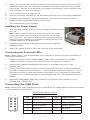
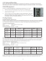
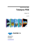
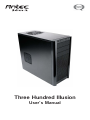
Three Hundred Illusion
User’s Manual
At Antec, we continually refine and improve our products to ensure the highest quality.
As such, your new case may differ slightly from the description in this manual. This isn’t a
problem; it’s simply an improvement. As of the date of publication, all features, descriptions,
and illustrations in this manual are correct.
Disclaimer
This manual is intended only as a guide for Antec’s computer enclosures. For more
comprehensive instructions on installing the motherboard and peripherals, please
refer to the user’s manuals that come with those components.
Three Hundred Illusion User’s Manual
Three Hundred Illusion – Gaming Case
The Three Hundred Illusion comes without a power supply. Make sure you choose a power
supply that is compatible with your computer components and has a long enough power
harness to reach your motherboard and peripheral devices. We recommend our TruePower
Quattro, EarthWatts, or TruePower New power supplies for the latest ATX specification
compliance, broad compatibility, and power savings capability.
Although care has been taken to prevent sharp edges in your Antec case, we strongly
recommend taking the appropriate time and care when working with it. Avoid hurried or
careless motions. Please use reasonable precaution.
Setting Up
1.
Place the case upright on a flat, stable surface so that the rear
panel (power supply and expansion slots) is facing you.
2.
Remove the panel thumbscrews from a side panel and open it
by swinging it outwards.
Note: Place the panel thumbscrews carefully aside as they are
NOT interchangeable with the HDD cage thumbscrews.
3.
Remove the panel thumbscrews from the other side panel to
open it. Place the screws carefully aside.
4.
There are three plastic tabs on the left side of the bezel. They
fasten the front bezel to the metal chassis. Release the tabs
from the top down to release the bezel. Swing open the bezel
to about 45º angles and gently lift the bezel upward. The front
bezel will come off easily. Set the bezel in a safe place.
5.
Inside the chassis is the power supply mount at the lower
rear of the case. You will also find some wiring with marked
connectors (USB, PWR etc.), an installed I/O panel and a
toolbox containing more hardware (screws, brass standoffs, etc.)
Note: Don’t use your fingernail to pry or lift the panels.
Installing the Motherboard
This manual is not designed to cover CPU, RAM, or expansion card installation. Please consult
your motherboard user’s manual for specific mounting instructions and troubleshooting.
Before proceeding, check the manual for your CPU cooler to find out if there are steps you
must do before installing the motherboard.
1.
Lay the case down so that the open side is up.
2.
Make sure you have the appropriate I/O panel for the motherboard. If the panel provided
is not suitable for the motherboard, please contact the motherboard manufacturer for
the correct I/O panel.
1
3.
Line up the motherboard with the standoff holes. Determine which holes line up and
remember where they are. (Not all motherboards will match with all of the provided
screw holes, and this is not necessary for proper functionality.) Some standoffs may
be pre-installed for your convenience.
4.
Lift up and remove the motherboard.
5.
Screw in the brass standoffs to the threaded holes that line up with the motherboard.
6.
Place the motherboard on the brass standoffs. Screw in the motherboard to the
standoffs with the provided Phillips-head screws.
7.
The motherboard is now installed.
Installing the Power Supply
1.
With the case upright, place the power supply on the bottom of
the case.
Note: Power supplies with fans on the bottom of the power
supply will need to be mounted so that the fan is facing the
top of the case. The Three Hundred Illusion provides mounting
holes for power supplies with standard mounting layouts to be
installed upside up or upside down.
2.
Push the power supply to the back of the case and align the
mounting holes.
3.
Attach the power supply to the case with the screws provided.
Connecting the Ports and LEDs
Note: Please refer to your motherboard user’s manual for specific pin outs or location of
front panel connectors.
1.
Connect the Reset switch (labeled RESET SW) to the motherboard at the RST
connector. Polarity (positive and negative) does not matter for switches.
2.
Power Switch (labeled POWER SW) connects to the PWR connector on the
motherboard.
3.
Connect the Power LED connector to the Power LED connector on the motherboard.
For LEDs, colored wires are positive (+). White or black wires are negative (–). If the
LED does not light up when the system is powered on, try reversing the connection.
For more info on connecting LEDs to your motherboard, see your motherboard user’s
manual.
4.
Hard Drive LED (labeled HDD LED) connects to the drive activity header on your
motherboard or RAID card.
Connecting the USB Ports
Note: Please check your motherboard user’s manual for the USB header pin layout and make
sure it matches the table below.
Motherboard USB Pin Layout
1
2
9 10
Pin
Signal Names
Pin
Signal Names
1
USB Power 1
2
USB Power 2
3
Negative Signal 1
4
Negative Signal 2
5
Positive Signal 1
6
Positive Signal 2
7
Ground 1
8
Ground 2
9
Key (No Connection)
10
Empty Pin
2
Connecting the Audio Ports (AC’97 and HDA)
There is an Intel® standard 10-pin AC’97 connector and an Intel® 10-pin HDA (High Definition
Audio) connector. You can connect either the AC’97 or the HDA connector, but not both at
once, to your motherboard depending on the spec of the motherboard.
Pin Assignment for Audio Ports (HDA and AC’97)
Locate the internal audio connectors from your motherboard or sound card. Consult your
motherboard or sound card manual for the pin-out positions.
Pin Assignment for Audio Ports (HDA and AC’97)
10 6 4 2
97531
Pin
Signal Names
(HDA)
Pin
Signal Names
(AC’97)
1
MIC2 L
1
MIC In
2
AGND
2
GND
3
MIC2 R
3
MIC Power
4
AVCC
4
NC
5
FRO-R
5
Line Out (R)
6
MIC2_JD
6
Line Out (R)
7
F_IO_SEN
7
NC
8
Key (no pin)
8
Key (no pin)
9
FRO-L
9
Line Out (L)
10
LINE2_JD
10
Line Out (L)
External 5.25” Device Installation
1.
Remove both side panels and front bezel per the instructions in Setting Up.
2.
Remove the drive bay faceplate from the bezel.
3.
Slide the 5.25” device into the bay from the front of the case.
4.
Fasten the drive using the screws that came with your drive.
5.
Connect the appropriate power and interface connectors from the power supply and
motherboard to the device.
6.
Mount the other devices accordingly.
3.5” Hard Drive Installation
1.
Remove both side panels and front bezel per the instructions in Setting Up.
2.
There are two 120mm fan cages at the front. Each fan cage covers 3 HDD bays and is
fastened by two thumbscrews.
3.
Loosen the two thumbscrews. Swing open the fan cage and gently lift upwards to
remove it. Up to six hard drives total can be installed.
4.
Slide a hard disk into a bay from the front of the case.
5.
Fasten the drive in place using the thumbscrews that came with the case.
6.
Connect the appropriate power and interface connectors from the power supply and
motherboard to the device.
7.
Repeat the procedure for additional drives as necessary.
8.
Put the front fan cages back to the case. If you plan to mount the optional 120mm
case fans, you should do it now. See Cooling section for fan installation.
3
3.5” External Drive Bay
Note: This case does not come with an external 3.5” drive bay. To install an external 3.5”
drive bay, you need to contact Antec Customer Support to purchase a 5.25” to 3.5” adapter.
Cable Management
There is a cable management compartment behind the 3.5” cage.
1.
Open the right side panel per the instruction in Setting Up.
2.
You will see the compartment with cable ties located behind the
wall of the 3.5” cage.
3.
Tuck or route your excess cables to the compartment. This will
keep the cables from interfering with airflow in your case and
help with cooling. Secure the cables to the wall of the 3.5” cage
as needed, with the reusable cable ties.
Cooling System
The Rear Exhaust TriCool™ Fan
There is a 120 x 25mm TriCool™ fan preinstalled at the rear of the case. The fan is installed
so the air will be blown out of the case. This fan comes with a three-speed switch that lets
you choose the speed best suited to your need. The default fan speed setting is Low.
120mm Fan Specifications:
Size:
120 x 25mm TriCool™ Fan
Rated Voltage:
12V DC
Operating Voltage: 10.2V ~ 13.8V
Speed
(RPM)
Input
Current
Airflow
Static Pressure
Noise
Input
Power
High
2000
0.24A
(max.)
2.24 m³ / min
(79 CFM)
2.54mm-H2O
(0.10inch-H2O)
30 dBA
2.9W
Medium
1600
0.2A
1.59 m³ / min
(56 CFM)
1.53mm-H2O
(0.06inch-H2O)
28 dBA
2.4W
Low
1200
0.13A
1.1 m³ / min
(39 CFM)
0.92mm-H2O
(0.04inch-H2O)
25 dBA
1.6W
The Top Exhaust TwoCool™ Fan With Blue LEDs
The case comes with a 140mm top exhaust fan. The fan is installed so the air will be blown
out of the case. This fan comes with a two-speed switch that lets you choose the speed
best suited to your need. The default fan speed setting is Low.
140mm TwoCool™ Specifications:
Size:
140 x 140 x 25mm TwoCool™ Fan
Rated Voltage:
DC 12V
Operating Voltage: 10.8V ~ 13.2V
Speed
(RPM)
Input
Current
Airflow
Static Pressure
Acoustical
Noise
Input
Power
High
1,200
0.3A
(max.)
1.7 m³ / min
(58.9 CFM)
0.8mm-H2O
(0.03inch- H2O)
26 dBA
3.6W
Low
800
0.2A
0.95 m³ / min
(33.6 CFM)
0.28mm- H2O
(0.011inch- H2O)
21.8 dBA
2.4W
Note: These TwoCool™ fans have a two-speed switch that lets you choose between quiet or
maximum cooling. The switch is located at the end of a short wire attached to the fan.
4
The Front Intake TwoCool™ Fan With Blue LEDs
The case comes with two 120mm fans that are installed to blow air into the case. This fan
comes with a two-speed switch that lets you choose the speed best suited to your need.
The default fan speed setting is Low.
Speed
(RPM)
Input
Current
Airflow
Static Pressure
Acoustical
Noise
Input
Power
High
1,500
0.3A
(max.)
1.434 m³ / min
(51.2 CFM)
1.212mm-H2O
(0.047inch- H2O)
27.9 dBA
3.6W
Low
900
0.18A
0.0843 m³ / min
(30.1 CFM)
0.486mm- H2O
(0.02inch- H2O)
16.9 dBA
2.16W
Note: The minimum voltage to start a typical TwoCool™ fan is 5V. We recommend that you
set the fan speed to High if you choose to connect the fan(s) to a fan control device or to
the Fan-Only connector found on some Antec power supplies. A fan control device regulates
the fan speed by varying the voltage, which may start as low as 4.5V to 5V. Connecting a
TwoCool™ fan set on Low to a fan-control device may result in the fan not being able to start
because the already lowered voltage from the fan control device will be further reduced by
the TwoCool™ circuitry below 5V.
Optional Fans
There is one optional 120mm fan mount—one side intake fan (on the left side panel). We
recommend using an Antec 120mm TriCool™ fan and setting the speed to Low. These fans
must be installed so that the air is blowing into the case.
The Side 120mm Fan — The side fan opening is there to enhance graphic cards cooling. The fan
should be installed so that air is blowing into the case.
Washable Air Filter
The front air filter – There is a filter located behind the front bezel.
To remove the filter:
1.
Remove the front bezel per the instructions in Setting Up.
2.
There is a tab on the left upper corner of the filter. Lift that
tab while releasing the latches down the side of the filter that
secure it to the bezel.
From time to time it will be necessary to wash the installed air filter. Not washing the
air filter will result in higher system temperatures and possible stability problems. We
recommend checking the air filter at least once a month initially. The frequency will change
depending on system usage (users whose systems run 24/7 will likely have to check/wash
more often than those who don’t use their systems every day) and on environmental
conditions.
5
Antec, Inc.
47900 Fremont Blvd.
Fremont, CA 94538
USA
tel: 510-770-1200
fax: 510-770-1288
Antec Europe B.V.
Stuttgartstraat 12
3047 AS Rotterdam
The Netherlands
tel: +31 (0) 10 462-2060
fax: +31 (0) 10 437-1752
Customer Support:
US & Canada
1-800-22ANTEC
[email protected]
Europe
+31 (0) 10 462-2060
[email protected]
www.antec.com
© Copyright 2009 Antec, Inc. All rights reserved.
All trademarks are the property of their respective owners.
Reproduction in whole or in part without written permission is prohibited.
Printed in China.