1
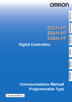
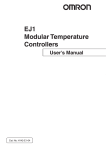
Allen-Bradley Bulletin
900 Driver Help
© 2012 Kepware Technologies
Allen-Bradley Bulletin 900 Driver Help
2
Table of Contents
Table of Contents
2
Allen-Bradley Bulletin 900 Driver Help
3
Overview
3
Driver Setup
4
Device Setup
5
5
Process Value Scaling
Automatic Tag Database Generation
7
Data Types Description
8
Address Descriptions
10
Error Descriptions
25
Allen-Bradley 900 Error Codes List
25
Address Validation
27
Missing address
27
Device address '<address>' contains a syntax error
27
Address '<address>' is out of range for the specified device or register
27
Device address '<address>' is not supported by model '<model name>'
27
Data Type '<type>' is not valid for device address '<address>'
27
Device address '<address>' is read only
28
28
Serial Communications
COMn does not exist
28
Error opening COMn
28
COMn is in use by another application
28
Unable to set comm parameters on COMn
28
Communications error on '<channel name>' [<error mask>]
29
29
Device Status Messages
Device '<device name>' is not responding
29
Unable to write to '<address>' on device '<device name>'
29
30
Device Specific Messages
Device '<device name>' responded with error. (Tag '<tag address>')
Automatic Tag Database Generation Messages
Unable to generate a tag database for device '<device name>'
Index
30
30
30
31
www. kepware.com
Allen-Bradley Bulletin 900 Driver Help
3
Allen-Bradley Bulletin 900 Driver Help
Help version 1.025
CONTENTS
Overview
What is the Allen-Bradley Bulletin 900 Driver?
Device Setup
How do I configure a device for use with this driver?
Driver Setup
How do I configure this driver?
Automatic Tag Database Generation
How can I easily configure tags for this driver?
Data Types Description
What data types does this driver support?
Address Descriptions
How do I address a data location on an Allen-Bradley Bulletin 900 device?
Error Descriptions
What error messages does the Allen-Bradley Bulletin 900 driver produce?
Overview
The Allen-Bradley Bulletin 900 driver provides an easy and reliable way to connect Allen-Bradley Bulletin 900
devices to OPC Client applications, including HMI, SCADA, Historian, MES, ERP and countless custom applications.
www. kepware.com
Allen-Bradley Bulletin 900 Driver Help
4
Driver Setup
Channel Properties
A channel represents a serial line connected to one of the computer's COM ports or an Ethernet network connected to the computer's default Network Interface Card (NIC). The Channel Properties allow users to specify the
connection type and other properties that will be shared by devices on that network.
Device Properties
Each physical device to be polled must be represented by a device object in the server. For information on the
Allen-Bradley Bulletin 900's device-specific dialog, refer to Process Value Scaling.
www. kepware.com
Allen-Bradley Bulletin 900 Driver Help
5
Device Setup
Supported Devices
Allen-Bradley Bulletin 900-TC8
-TC8 w/Enhanced Features
-TC16
-TC16 w/Enhanced Features
-TC32
Communication Protocol
Allen-Bradley Bulletin 900-TCx Protocol as detailed in Publication 900-UM004A-EN-E -September 2003.
Allen-Bradley Bulletin 900-TCx Protocol as detailed in Publication 900-UM004B-EN-E -June 2005 (CompoWay/F(SYSWAY)).
Supported Communication Parameters
Baud Rate: 1200, 2400, 4800, 9600, 19200, 38400*
Parity: None, Even, or Odd
Data Bits: 7 or 8
Stop Bits: 1 or 2
*TC8 w/Enhanced Features and TC16 w/Enhanced Features only.
Ethernet Encapsulation
This driver supports Ethernet Encapsulation, which allows the driver to communicate with serial devices
attached to an Ethernet network using a terminal server. It may be invoked through the COM ID dialog in Channel
Properties. For more information, refer to the OPC server's help documentation.
Device IDs
This parameter specifies the unique ID that will be used in order to communicate with other devices. The valid
range is 0 to 99.
Flow Control
When using an RS232/RS485 converter, the type of flow control that is required depends on the needs of the converter. Some converters do not require any flow control whereas others require RTS flow. Consult the converter's
documentation in order to determine its flow requirements. An RS485 converter that provides automatic flow control is recommended.
Note: When using the manufacturer's supplied communications cable, it is sometimes necessary to choose a
flow control setting of RTS or RTS Always under the Channel Properties.
Cable Connections
Refer to each individual controller's manual section on both Hardware Installation and Wiring in Publication 900UM004A-EN-E or 900-UM004B-EN-E.
Process Value Scaling
Process Value Scaling (and its related parameters) scales values according to the input type. For an input type
that has no scaling, the value read from the device will match that of the display. For an input type that is scaled
by 10, the value read from the device will be 10 times that of the value displayed on the front panel. A division by
10 is necessary. Input type selection is used for enhanced models only. Some addresses are scaled differently
depending on the input type of device. If this item is set incorrectly, the value returned by the driver will not
match what is displayed by the device.
Process value scaling allows the driver to automatically perform scaling for reading and writing process value
related parameters. It is handled by the driver in a similar fashion as parameters with fixed scaling by 10.
Note: To determine if scaling is required for a given input type, refer to the controller's manual section on sensor
input setting ranges.
www. kepware.com
Allen-Bradley Bulletin 900 Driver Help
6
Descriptions of the parameters are as follows:
l
Process Value Scaling: When checked, this setting will be enabled along with the Process Value Scaling
Factor used for all applicable tags. For a list of tags, refer to Data Types Description.
l
Process Value Scaling Factor: This parameter specifies the scaling factor. The valid range is from 0.1
to 1,000.
l
Input Type: This parameter specifies the type of input. There are two options: TC/Pt Multi Input or
Analog Input.
Note: When process value scaling is disabled, it behaves the same as no scaling. For more information, refer to
Data Types Description.
www. kepware.com
Allen-Bradley Bulletin 900 Driver Help
7
Automatic Tag Database Generation
The Allen-Bradley Bulletin 900 Driver utilizes the OPC server's automatic tag database generation feature, which
enables drivers to automatically create tags to access data. This is accomplished either by querying the device for
its configuration or by using a fixed database to access information to build a tag database.
OPC Server Configuration
The automatic tag database generation feature can be customized to fit a specific application's needs. The primary control options are set during the Database Creation step of the Device Wizard, but may be accessed later
by clicking Device Properties | Database Creation. For more information, refer to the OPC server's help documentation.
Operation
Depending on the configuration, tag generation may start automatically when the OPC server project starts or be
initiated manually at some other time. The OPC server's Event Log will show when the tag generation process
started, any errors that occurred while building the tag database and when the process was completed.
Group and Tag Naming
A group is created in the server for each group, excepting the operation and operational groups. These are combined into one Operation group. For more information (including the name that will be generated for each tag/address) refer to Address Descriptions.
The image below displays the results of automatic tag database creation for a TC-8.
www. kepware.com
Allen-Bradley Bulletin 900 Driver Help
8
Data Types Description
Data Type
Description
DWord
Read: Unsigned 32 bit value read from the device.
Long
Read: Unsigned 32 bit value read from the device.
Write: Value passed directly on to the device.
Write: Value passed directly on to the device.
Float
A scaling algorithm may be applied to each data item. The following information details each variation of
type Float.
No Scaling/Process Value Scaling Disabled
Read: Value returned from the device is converted to Float.
Write: Value written goes through the following conversion process before being sent to the device.
1. Rounded to the next whole number.
2. Fractional part is removed.
3. Integer part is sent to the device.
Note: No scaling items can be identified if the hexadecimal range is the same as the decimal range.
For example, C0:0009, Soak time remain monitor, 00000000 to 0000270F (0 to 9999).
Variable Scaling (By Process Value Scaling Factor)*
Read: Value returned from the device is converted to Float and then divided by the process value scaling
factor.
Write: Value written goes through the following conversion process before being sent to the device.
1. Fractional part is rounded to the hundredths position.
2. Multiplied by the Process Value Scaling Factor.
3. Fractional part is removed.
4. Integer part is sent to the device.
Note: Variable scaling items are all of the process and set point related items. This includes the following specific addresses: C0:0000, C0:0002, C1:0003, C1:000E, C1:000F, C1:0010, C1:0011,
C3:0005 and C3:0006.**
Fixed Scaling (By an Address-Specific Scaling Factor)
Read: Value returned from the device is converted to Float and then divided by the address's appropriate value.
Write: Value written goes through the following conversion process before being sent to the device.
1. Fractional part is rounded to the hundredths position.
2. Multiplied by the value appropriate for address.
3. Fractional part is removed.
4. Integer part is sent to the device.
Note: Fixed scaling items have an implied decimal point in the actual value transferred by the device.
These can be identified by whether or not the hexadecimal range is different than the decimal range.
For example, C0:0005, MV monitor (OUT2), 00000000 to 0000041A (0.0 to 105.0).
Boolean
Read: If the value returned from the device is zero, then FALSE is returned. If the value returned from
device is nonzero, then TRUE is returned.
Write: Value passed directly on to the device.
*This is only true if process value scaling is enabled.
**For information on setup, refer to Process Value Scaling.
www. kepware.com
Allen-Bradley Bulletin 900 Driver Help
9
See Also: Address Descriptions.
www. kepware.com
Allen-Bradley Bulletin 900 Driver Help
10
Address Descriptions
To form a tag address, combine a variable type and address and then separate them with a colon. Tag addresses
have the following syntax: Variable_Type:Address. For examples of tag addresses, refer to the table below.
Variable Type
Address
Tag Address
C0
0000
C0:0000
C0
0001
C0:0001
For the Status Item only (C0:0001), access to individual status bits listed in the Status Bits Table is provided
using the following additional syntax: Variable_Type:Address/Bit_Number. For examples, refer to the table
below. For more information, refer to Status Bits Table.
Variable Type
Address
Bit Number
Tag Address
Data Type
C0
0001
8
C0:0001/8
Boolean
C0
0001
9
C0:0001/9
Boolean
Note: For information on how each data type is treated by driver, refer to Data Types Description.
Bulletin 900-TCxx Groups
The tables below list the available tag addresses for each of the groups in the Bulletin 900-TCxx. Each group's
setup area is detailed so that users will be able to determine whether a service command (to move to the appropriate setup area) is required when performing a write operation.
For example, before performing any write operation to a setup area 1 parameter, users must move to setup area 1
by using the Service 07 tag. To view the current setup area, refer to the corresponding bit in the status address.
Before performing any write operation to a Protect Level Group parameter, users also need to move to protect
level by using the Service 08 tag.
Setup Areas
Area
Description
Setup Area 0
This area groups together the protect, operation, operational and
adjustment level/group.
Setup Area 1
This area groups together the initial setting, communications setting,
advanced function setting and calibration level/group.
Note: Access to the Calibration Level Group is not provided by the driver.
Services Group
Services group tag addresses are primarily provided as a way to perform the same functionality as the frontpanel keys. For example, pressing the level key for at least 3 seconds moves to the initial setting function group.
This same functionality is provided by the Service 07 tag. Likewise, pressing the Level key for at least 1 second
moves to the operations function group and displays the process value and set point. This same functionality is
provided by Service 06 tag. For more information, refer to Services Group table.
Quick Links to Tables
Operational Level/Group (Setup Area 0)
Protect Level/Group (Setup Area 0)
Operation Level/Group (Setup Area 0)
Adjustment Level/Group (Setup Area 0)
Communications Setting Level/Group (Setup Area 1)
Initial Setting Level/Group (Setup Area 1)
Advanced Function Setting Level/Group (Setup Area 1)
Status Bits Table
Services Group
Operational Level/Group - (Setup Area 0)
Operational Function Group - (Setup Area 0)
Variable
Type
Address
Item (Parameter)
Set Value
Access
Models
Data
Types
ATG Name
C0
0000
Process
value
Temperature:
Read
Only
All
Float
DWord
Process_Value
www. kepware.com
Allen-Bradley Bulletin 900 Driver Help
11
Follow the specified
range
of the sensor.
Long
Analog: Scaling lower
limit
-5%FS to scaling
upper limit
+5%FS
C0
0001
Status
(1)
Refer to Status Bits
Table
Read
Only
All
DWord
Long
Float
Boolean
Status
C0
0002
Internal
set point
(1)
SP lower limit to
SP upper limit
Read
Only
All
Float
DWord
Long
Internal_Set_Point
C0
0003
Heater current
monitor
00000000 to
00000226
(0.0 to 55.0)
Read
Only
TC8,
TC8 E
TC16
TC16 E
Float
DWord
Long
Heater_Current_Monitor
C0
0004
MV
monitor (OUT1)
Standard:
FFFFFFCE to
0000041A
(-5.0 to 105.0)
Read
Only
All
Float
DWord
Long
MV_Monitor_OUT_1
Heating and
cooling:
00000000 to
0000041A
(0.0 to 105.0)
C0
0005
MV
monitor (OUT2)
00000000 to
0000041A
(0.0 to 105.0)
Read
Only
All
Float
DWord
Long
MV_Monitor_OUT_2
C0
0006
Heater current
value 2 monitor
00000000 to
00000226
(0.0 to 55.0)
Read
Only
TC8 E
TC16 E
Float
DWord
Long
Heater_Current_2_
Monitor
C0
0007
Leakage current
value 1 monitor
00000000 to
00000226
(0.0 to 55.0)
Read
Only
TC8 E
TC16 E
Float
DWord
Long
Leakage_Current_1_
Monitor
C0
0008
Leakage current
value 2 monitor
00000000 to
00000226
(0.0 to 55.0)
Read
Only
TC8 E
TC16 E
Float
DWord
Long
Leakage_Current_2_
Monitor
C0
0009
Soak
time
remain monitor
00000000 to
0000270F
(0 to 9999)
Read
Only
TC8 E
TC16 E
Float
DWord
Long
Soak_Time_Remain_
Monitor
Note: Not displayed on the controller's display.
Protect Level/Group - (Setup Area 0)
Protect Function Group - (Setup Area 0)
Variable Address Item (ParamType
eter)
C1
0000
Set Value
Operation /
00000000(0)
adjustment pro- No restrictions in operation and
tection
adjustment levels
00000001(1)
Move to adjustment level
restricted
00000002(2)
Display and change of only "PV" and
www. kepware.com
Access
Models Data
Types
Read/Write All
DWord
Long
Float
Boolean
ATG
Name
Operation_
Adj_Protect
Allen-Bradley Bulletin 900 Driver Help
12
"PV/SP"
parameters enabled
00000003(3)
Display of only "PV" and "PV/SP"
parameters enabled
C1
0001
Initial setting /
comms. protection
00000000(0) Move to initial setting/comms. setting level enabled
(move to
advanced function
setting level displayed)
Read/Write All
DWord
Long
Float
Boolean
Initial_
Set_
Comm_Protect
Read/Write All
DWord
Setup_
Long
Change_
Float
Protect
Boolean
00000001(1) Move to initial setting/comms. setting level enabled
(move to
advanced function
setting level not displayed)
00000002(2) Move to initial setting /
comms.
setting level restricted
C1
0002
Setup change
protection
00000000(0)
OFF (changing of
setup on controller display
enabled)
00000001(1)
ON (changing of
setup on controller display
disabled)
Operation Level/Group - (Setup Area 0)
Operation Function Group - (Setup Area 0)
Variable
Type
Address
Item (Parameter)
Set Value
Access
Models
Data
Types
ATG Name
C1
0003
Set point
SP lower limit to
SP upper limit
Read/Write
All
Float
DWord
Long
Set_Point
C1
0004
Alarm value 1
FFFFF831 to
0000270F
(-1999 to 9999)
Read/Write
All
Float
DWord
Long
Alarm_Value1
C1
0005
Upper-limit alarm 1
FFFFF831 to
0000270F
(-1999 to 9999)
Read/Write
All
Float
DWord
Long
Upper_Limit_
Alarm1
C1
0006
Lower-limit alarm 1
FFFFF831 to
0000270F
(-1999 to 9999)
Read/Write
All
Float
DWord
Long
Lower_Limit_
Alarm1
C1
0007
Alarm value 2
FFFFF831 to
0000270F
(-1999 to 9999)
Read/Write
TC8,
TC8 E,
TC16,
TC16 E
Float
DWord
Long
Alarm_Value2
C1
0008
Upper-limit alarm 2
FFFFF831 to
0000270F
(-1999 to 9999
Read/Write
TC8,
TC8 E,
TC16,
TC16 E
Float
DWord
Long
Upper_Limit_
Alarm2
C1
0009
Lower-limit alarm 2
FFFFF831 to
0000270F
(-1999 to 9999)
Read/Write
TC8,
TC8 E,
TC16,
TC16 E
Float
DWord
Long
Lower_Limit_
Alarm2
C1
000A
Alarm value 3 (1) (2)
FFFFF831 to
0000270F
(-1999 to 9999)
Read/Write
TC8,
TC8 E,
TC16 E
Float
DWord
Long
Alarm_Value3
C1
000B
Upper-limit alarm 3 (1)
FFFFF831 to
Read/Write
TC8,
Float
Upper_Limit_
www. kepware.com
Allen-Bradley Bulletin 900 Driver Help
13
C1
000C
(2)
0000270F
(-1999 to 9999)
Lower-limit alarm 3 (1)
(2)
FFFFF831 to
0000270F
(-1999 to 9999)
Read/Write
TC8 E,
TC16 E
DWord
Long
Alarm3
TC8,
TC8 E,
TC16 E
Float
DWord
Long
Lower_Limit_
Alarm3
Note 1: Only displayed on the 900-TC8. The alarm function can also be used on units without alarm outputs. In
this case, confirm alarm occurrences via the status data.
Note 2: When alarm 3 is not assigned to an output, the parameter will not be shown on the controller's display.
Adjustment Level/Group - (Setup Area 0)
Adjustment Function Group - (Setup Area 0
Variable Address Item
Type
(Parameter)
Set Value
Access
Models Data
Types
ATG Name
C1
000D
Heater burnout
detection
00000000 to 000001F4
(0.0 to 50.0)
Read/Write TC8,
TC8 E,
TC16,
TC16
E
Float
DWord
Long
Heater_Burnout_Detection
C1
000E
Set point 0
SP lower limit to
SP upper limit
Read/Write All
Float
DWord
Long
Set_Point0
C1
000F
Set point 1
SP lower limit to
SP upper limit
Read/Write All
Float
DWord
Long
Set_Point1
C1
0010
Set point 2
SP lower limit to
SP upper limit
Read/Write All
Float
DWord
Long
Set_Point2
C1
0011
Set point 3
SP lower limit to
SP upper limit
Read/Write All
Float
DWord
Long
Set_Point3
C1
0012
Temperature
input shift
FFFFF831 to 0000270F
(-199.9 to 999.9)
Read/Write All
Float
DWord
Long
Temp_Input_
Shift
C1
0013
Upper-limit temperature input
shift value
FFFFF831 to 0000270F
(-199.9 to 999.9)
Read/Write All
Float
DWord
Long
Upp_Lim_
Temp_Input_
Shift
C1
0014
Lower-limit temperature input
shift value
FFFFF831 to 0000270F
(-199.9 to 999.9)
Read/Write All
Float
DWord
Long
Low_Lim_
Temp_Input_
Shift
C1
0015
Proportional
band
00000001 to 0000270F
(0.1 to 999.9)
Read/Write All
Float
DWord
Long
Proportional_
Band
C1
0016
Integral time
00000000 to 00000F9F
(0 to 3999)
Read/Write All
Float
DWord
Long
Integral_Time
C1
0017
Derivative time
00000000 to 00000F9F
(0 to 3999)
Read/Write All
Float
DWord
Long
Derivative_
Time
See Table 5.AF in Bulletin 900-TC8
and 900-TC16 User Manual
C1
0018
Cooling coefficient
00000001 to 0000270F
(0.01 to 99.99)
Read/Write All
Float
DWord
Long
Cooling_Coefficient
C1
0019
Dead band
FFFFF831 to 0000270F
(-199.9 to 999.9)
Read/Write All
Float
DWord
Long
Dead_Band
Read/Write All
Float
DWord
Long
Manual_
Reset_Value
See Table 5.AH in Bulletin 900-TC8
and 900-TC16 User Manual
C1
001A
Manual reset
value
00000000 to 000003E8
(0.0 to 100.0)
www. kepware.com
Allen-Bradley Bulletin 900 Driver Help
C1
001B
Hysteresis
(OUT1)
14
00000001 to 0000270F
(0.1 to 999.9)
Read/Write All
Float
DWord
Long
Hysteresis_
OUT1
Read/Write All
Float
DWord
Long
Hysteresis_
OUT2
See Table 5.AJ in Bulletin 900-TC8
and 900-TC16 User Manual
C1
001C
Hysteresis
(OUT2)
00000001 to 0000270F
(0.1 to 999.9)
See Table 5.AJ in Bulletin 900-TC8
and 900-TC16 User Manual
C1
001D
Heater burnout 2 00000000 to 000001F4
detection
(0.0 to 50.0)
Read/Write TC8 E
TC16 E
Float
DWord
Long
Heater_Burnout_2_Detection
C1
001E
HS alarm 1
00000000 to 000001F4
(0.0 to 50.0)
Read/Write TC8 E
TC16 E
Float
DWord
Long
HS_Alarm_1
C1
001F
HS alarm 2
00000000 to 000001F4
(0.0 to 50.0)
Read/Write TC8 E
TC16 E
Float
DWord
Long
HS_Alarm_2
C1
0020
Soak time
00000001 to 0000270F
(1 to 9999)
Read/Write TC8 E
TC16 E
Float
DWord
Long
Soak_Time
C1
0021
Wait Band
00000000 (0): OFF
00000001 to 0000270F
(0.1 to 999.9 for TC/Pt multi-input
models) (0.01 to 99.99 for Analog
input models)
Read/Write TC8 E
TC16
E
Float
DWord
Long
Wait_Band
See Table 5.AL in Bulletin 900-TC8
and 900-TC16 User Manual
C1
0022
MV at stop
Standard: FFFFFFCE to 0000041A
(−5.0 to 105.0)
Heating and cooling: FFFFFBE6 to
0000041A (−105.0 to 105.0)
Read/Write TC8 E
TC16 E
Float
DWord
Long
MV_at_Stop
C1
0023
MV at PV error
Standard: FFFFFFCE to 0000041A
(−5.0 to 105.0)
Heating and cooling: FFFFFBE6 to
0000041A (−105.0 to 105.0)
Read/Write TC8 E
TC16 E
Float
DWord
Long
MV_at_PV_
Error
C1
0024
Manual manipulated variable
Standard: FFFFFFCE to 0000041A
(−5.0 to 105.0)
Heating and cooling: FFFFFBE6 to
0000041A (−105.0 to 105.0)
Read/Write TC8 E
TC16 E
Float
DWord
Long
Manual_Manipulated_Variable
C1
0025
SP ramp set
value
00000000 (0): OFF
00000001 to 0000270F (1 to
9999)
Read/Write TC8 E
TC16 E
Float
DWord
Long
SP_Ramp_
Set_Value
C1
0026
MV upper limit
Standard: MV lower limit + 0.1 to
0000041A (MV lower limit + 0.1 to
105.0)
Heating and cooling: 00000000 to
0000041A (0.0 to 105.0)
Read/Write TC8 E
TC16 E
Float
DWord
Long
MV_Upper_
Limit
C1
0027
MV lower limit
Standard: FFFFFFCE to MV upper
limit − 0.1 (−5.0 to MV upper limit
− 0.1)
Heating and cooling: FFFFFBE6 to
00000000 (−105.0&0.0)
Read/Write TC8 E
TC16
E
Float
DWord
Long
MV_Lower_
Limit
C1
0028
Move Protect
function group
FFFFF831 to 0000270F
(−1999 to 9999)
Read/Write TC8 E
TC16
E
Float
DWord
Long
Move_Protect_
Group
C1
0029
Password to
Move to Protect
function group
FFFFF831 to 0000270F
(−1999 to 9999) (Can only be set.
The monitor value is always
00000000.)
Read/Write TC8 E
TC16 E
Float
DWord
Long
Password_
Move2Protect_
Group
www. kepware.com
Allen-Bradley Bulletin 900 Driver Help
15
C1
002A
Parameter mask
enable
00000000 (0): OFF
00000001 (1): ON
Read/Write TC8 E
TC16 E
DWord
Parameter_
Long
Mask_Enable
Float
Boolean
Communications Setting Level/Group - (Setup Area 1)
Communications Setting Function Group - (Setup Area 1)
Variable
Type
Address
Item (Parameter)
Set Value
Access
Models
Data
Types
ATG Name
C3
0010
Communications unit
number (1)
00000000 to
00000063
(0 to 99)
Read/Write
All
DWord
Long
Float
Boolean
Comm_Unit_
Number
C3
0011
Baud rate (1)
00000000(0) 1.2
00000001(1) 2.4
00000002(2) 4.8
00000003(3) 9.6
00000004(4)
19.2
Read/Write
All
DWord
Long
Float
Boolean
Baud_Rate
C3
0012
Communications data
length (1)
00000007(7) 7
00000008(8) 8
Read/Write
All
DWord
Long
Float
Boolean
Comm_Data_
Length
C3
0013
Communications stop bit
(1)
00000001(1) 1
00000002(2) 2
Read/Write
All
DWord
Long
Float
Boolean
Comm_Stop_
Bit
C3
0014
Communications parity (1) 00000000(0)
None
00000001(1)
Even
00000002(2)
Odd
Read/Write
All
DWord
Long
Float
Boolean
Comm_Parity
Note: Communications parameters are enabled after they have been changed by resetting the controller.
Initial Setting Level/Group - (Setup Area 1)
Initial Setting Function Group - (Setup Area 1)
Variable Address Item (ParamType
eter)
Set Value
Access
C3
0000
Input type (1)
For models TC8 and TC16: see AB Publication 900-UM004A-EN-E (Sept. 2003)
Chapter 3 - Communications Data, Initial
Setting Level/Group table.
Read/Write All
DWord
Long
Float
Boolean
Input_Type
C3
0001
Scaling upper
limit
Scaling lower limit +1 to 0000270F (scaling lower limit +1 to 9999)
Read/Write All
Float
DWord
Long
Scaling_
Upp_Limit
C3
0002
Scaling lower
limit
FFFFF831 to Scaling upper limit -1 (-1999 Read/Write All
to scaling upper limit -1)
Float
DWord
Long
Scaling_
Low_Limit
C3
0003
Decimal point
position (TC/Pt
multi-input models)
00000000 to 00000001 (0 to 1)
Read/Write All
DWord
Long
Float
Boolean
Decimal_
Point
C3
0004
°C/°F selection
00000000(0) °C
00000001(1) °F
Read/Write All
DWord
Long
Float
Boolean
Cels_Fahr_
Select
C3
0005
SP upper limit
Temperature: SP lower limit +1 to Input
range upper limit
Read/Write All
Float
DWord
Long
SP_Upp_
Limit
Analog: SP lower limit +1 to scaling
www. kepware.com
Models Data
Types
ATG Name
Allen-Bradley Bulletin 900 Driver Help
16
upper limit
C3
0006
SP lower limit
Temperature: Input range lower limit to
SP upper limit -1
Read/Write All
Float
DWord
Long
SP_Low_
Limit
Read/Write All
DWord
Long
Float
Boolean
PID_OnOff_
Select
Std_HeatCool_Select
Analog: Scaling lower limit to SP upper
limit -1
C3
0007
PID/ ON/OFF
00000000(0) ON/OFF
00000001(1) 2-PID
C3
0008
Standard/Heating 00000000(0) Standard
and cooling
00000001(1) Heating and cooling
Read/Write All
DWord
Long
Float
Boolean
C3
0009
ST
00000000(0) OFF
00000001(1) ON
Read/Write All
DWord
Self_TunLong
ing
Float
Boolean
C3
000A
Control period
(OUT1)
00000001 to 00000063 (1 to 99)
Read/Write All
DWord
Long
Float
Boolean
Control_
Period_
OUT1
C3
000B
Control period
(OUT2)
00000001 to 00000063 (1 to 99)
Read/Write All
DWord
Long
Float
Boolean
Control_
Period_
OUT2
C3
000C
Direct/reverse
operation
00000000(0) Reverse operation
00000001(1) Direct operation
Read/Write All
DWord
Long
Float
Boolean
Direct_
Reverse_
Select
C3
000D
Alarm 1 type
00000000(0)
Read/Write All
Alarm function OFF
00000001(1)
Upper- and lower-limit alarm
00000002(2)
Upper-limit alarm
00000003(3)
Lower-limit alarm
00000004(4) Upper- and lower-limit
range alarm
00000005(5)Upper- and lower-limit
alarm with standby sequence
00000006(6)Upper-limitalarmwith
standby sequence
00000007(7)Lower-limit alarm with
standby sequence
00000008(8)Absolute-value upper-limit
alarm
00000009(9)Absolute-value lower-limit
alarm
0000000A(10) Absolute-value upperlimit alarm with standby sequence
0000000B(11) Absolute-value lower-limitalarm with standby sequence
0000000C(12) LBA (Loop Burnout alarm
DWord
Long
Float
Boolean
AlarmType1
C3
000E
Alarm 2 type
Same as alarm 1 type without Setting 12
DWord
Long
Float
Boolean
AlarmType2
www. kepware.com
Read/Write TC8,
TC8 E,
TC16,
TC16
E
Allen-Bradley Bulletin 900 Driver Help
17
C3
000F
Alarm 3 type (1)
(2)
Same as alarm 1 type without Setting 12
Read/Write TC8,
TC8 E,
TC16
E
DWord
Long
Float
Boolean
AlarmType3
Note 1: The input type can be selected according to the compatible sensor connected to the controller (depending on the controller catalog number).
Note 2: The parameter will not be shown on the controller's display when alarm 3 is not assigned to an output.
Advanced Function Setting Level/Group - (Setup Area 1)
Advanced Function Setting Function Group - (Setup Area 1)
Variable Address Item
Type
(Parameter)
Set Value
Access
Models Data
Types
ATG Name
C3
0015
Number of
multi-SP uses
00000000 (0): No multi-SP
00000001 (1): 2SP
00000002 (2): 4SP
Read/Write TCE 8
TCE
16
DWord
Long
Float
Boolean
Number_MultiSP_Uses
C3
0016
Event input
assignment 1
00000000 (0): None
00000001 (1): RUN/STOP (Cannot be set
if the Number of Multi-SP Uses is set to 1 or
2.)
00000002 (2): Auto/Manual (Cannot be set
if the Number of Multi-SP Uses is set to 1 or
2.)
00000003 (3): Program Start (Cannot be
set
if the Number of Multi-SP Uses is set to 1 or
2.)
Read/Write TCE 8
TCE
16
DWord
Long
Float
Boolean
Event_
Input_
Assignment_
1
C3
0017
Event input
assignment 2
00000000 (0): None
00000001 (1): RUN/STOP (Cannot be set
if the Number of Multi-SP Uses is set to 2.)
00000002 (2): Auto/Manual (Cannot be set
if the Number of Multi-SP Uses is set to 2.)
00000003 (3): Program Start (Cannot be
set
if the Number of Multi-SP Uses is set to 2.)
Read/Write TCE 8
TCE
16
DWord
Long
Float
Boolean
Event_
Input_
Assignment_
2
C3
001A
Multi-SP
00000000(0) OFF
00000001(1) ON
Read/Write All
DWord
Multi_SP
Long
Float
Boolean
C3
001B
SP ramp time
unit
00000000(0) EU/second
00000001(1) EU/minute
Read/Write All
DWord
Long
Float
Boolean
Spare/SP_
Ramp_Time_
Unit
C3
001C
SP ramp set
value
00000000(0) OFF
00000001 to 0000270F (1 to 9999)
Read/Write All
Float
DWord
Long
SP_Ramp_
Set_Value
C3
001D
Standby
sequence
reset method
00000000(0) Condition A
00000001(1) Condition B
Read/Write All
DWord
Long
Float
Boolean
Standby_
Seq_Reset_
Method
C3
001E
Alarm 1 open
in alarm
00000000(0) Close in alarm
00000001(1) Open in alarm
Read/Write All
DWord
Long
Float
Boolean
Alarm1_
Open_In_
Alarm
C3
001F
Alarm 1 hysteresis
00000001 to 0000270F (0.1
to 999.9)
Read/Write All
Float
DWord
Long
Alarm1_Hysteresis
Read/Write TC8,
DWord
Alarm2_
See Table 5.BY in Bulletin 900-TC8 and
900-TC16 User Manual
C3
0020
Alarm 2 open
00000000(0) Close in alarm
www. kepware.com
Allen-Bradley Bulletin 900 Driver Help
C3
0021
18
in alarm
00000001(1) Open in alarm
TC8 E,
TC16,
TC16
E
Alarm 2 hysteresis
00000001 to 0000270F (0.1
to 999.9)
See Table 5.BY in Bulletin 900-TC8 and
900-TC16 User Manual
Long
Float
Boolean
Open_In_
Alarm
Read/Write TC8,
TC8 E,
TC16,
TC16
E
Float
DWord
Long
Alarm2_Hysteresis
C3
0022
Alarm 3 open
in alarm (1)
(2)
00000000(0) Close in alarm
00000001(1) Open in alarm
Read/Write TC8,
TC8 E,
TC16
E
DWord
Long
Float
Boolean
Alarm3_
Open_In_
Alarm
C3
0023
Alarm 3 hysteresis (1)
(2)
00000001 to 0000270F (0.1
to 999.9)
Read/Write TC8,
TC8 E,
TC16
E
Float
DWord
Long
Alarm3_Hysteresis
See Table 5.BY in Bulletin 900-TC8 and
900-TC16 User Manual
C3
0024
HBA used
00000000(0) OFF
00000001(1) ON
Read/Write TC8,
TC8 E,
TC16,
TC16
E
DWord
HBA_Used
Long
Float
Boolean
C3
0025
Heater burnout latch
00000000(0) OFF
00000001(1) ON
Read/Write TC8,
TC8 E,
TC16,
TC16
E
DWord
Heater_BurnLong
out_Latch
Float
Boolean
C3
0026
Heater burnout hysteresis
00000001 to 00001F4 (0.1 to 50.0)
Read/Write TC8,
TC8 E,
TC16,
TC16
E
Float
DWord
Long
Heater_Burnout_Hysteresis
C3
0027
ST stable
range
00000001 to 0000270F (0.1
to 999.9)
Read/Write All
Float
DWord
Long
ST_Stable_
Range
C3
0028
α
00000000 to 00000064 (0.00 to 1.00)
Read/Write All
Float
DWord
Long
Alpha
C3
0029
MV upper
limit
Standard: MV lower limit +0.1 to 000041A
Read/Write All
Float
DWord
Long
MV_Upper_
Limit
Read/Write All
Float
DWord
Long
MV_Lower_
Limit
Input_Digital_Filter
(MV lower limit +0.1 to 105.0)
Heating and cooling: 00000000 to
0000041A
(0.0 to 105.0)
C3
002A
MV lower limit Standard: FFFFFFCE to MV upper limit -0.1
(-5.0 to MV upper limit -0.1)
Heating and cooling: FFFFFBE6 to
00000000
(-105.0 to 0.0)
C3
002B
Input digital
filter
00000000 to 0000270F (0.0 to 999.9)
Read/Write All
Float
DWord
Long
C3
002C
Additional PV
display
00000000(0) OFF
00000001(1) ON
Read/Write All
DWord
Additional_
Long
PV_Display
Float
Boolean
C3
002D
MV display
00000000(0) OFF (display of manipulated
Read/Write All
DWord
www. kepware.com
MV_Display
Allen-Bradley Bulletin 900 Driver Help
19
variable OFF)
00000001(1) ON (display of manipulated
variable ON)
Long
Float
Boolean
C3
002E
Automatic
return of display mode
00000000(0) OFF
00000001 to 00000063 (1 to 99)
Read/Write All
DWord
Long
Float
Boolean
Auto_
Return_Display_Mode
C3
002F
Alarm 1 latch
00000000(0) OFF
00000001(1) ON
Read/Write All
DWord
Alarm1_
Long
Latch
Float
Boolean
C3
0030
Alarm 2 latch
00000000(0) OFF
00000001(1) ON
Read/Write TC8,
TC8 E,
TC16,
TC16
E
DWord
Alarm2_
Long
Latch
Float
Boolean
C3
0031
Alarm 3 latch
(1) (2)
00000000(0) OFF
00000001(1) ON
Read/Write TC8,
TC8 E,
TC16
E
DWord
Alarm3_
Long
Latch
Float
Boolean
C3
0032
Protect level
move time
00000001 to 0000001E (1 to 30)
Read/Write All
DWord
Long
Float
Boolean
C3
0033
Input error
output
00000000(0) OFF
00000001(1) ON
Read/Write All
DWord
Input_
Long
Error_OutFloat
put
Boolean
C3
0034
Cold junction 00000000(0) OFF
compensation 00000001(1) ON
method
Read/Write All
DWord
Cold_JuncLong
tion_Comp_
Float
Method
Boolean
C3
0035
MB command
logic switching 1 (3)
00000000(0) OFF
00000001(1) ON
Read/Write All
DWord
MB_Cmd_
Long
Logic_
Float
Switching1
Boolean
C3
0036
PV color
change 2 (4)
For models TC8 and TC16: see AB PubRead/Write TC8 E,
lication 900-UM004A-EN-E (Sept. 2003)
TC16,
Chapter 3 - Communications Data, Advanced
TC16
Function Setting Level/Group table.
E
Protect_
Level_Move_
Time
DWord
Long
Float
Boolean
PV_Color_
Change2
Read/Write TC8 E,
TC16,
TC16
E
Float
DWord
Long
PV_Stable_
Band2
For models TC8 Enhanced and TC16
Enhanced: see AB Publication 900-UM004BEN-E (June 2005) Chapter 3 - Communications Data, Advanced Function Setting Function Group table.
C3
0037
PV stable
band 2
00000001 to 0000270F (0.1 to 999.9)
See Table 5.CO in Bulletin 900-TC8 and
900-TC16 User Manual
C3
0038
Alarm 1 ON
delay
00000000 to 000003E7 (0 to 999)
Read/Write TC8 E
TC16
E
Float
DWord
Long
Alarm_1_
ON_Delay
C3
0039
Alarm 2 ON
delay
00000000 to 000003E7 (0 to 999)
Read/Write TC8 E
TC16
E
Float
DWord
Long
Alarm_2_
ON_Delay
C3
003A
Alarm 3 ON
delay (2) (5)
00000000 to 000003E7 (0 to 999)
Read/Write TC8 E
TC16
E
Float
DWord
Long
Alarm_3_
ON_Delay
C3
003B
Alarm 1 OFF
delay
00000000 to 000003E7 (0 to 999)
Read/Write TC8 E
TC16
E
Float
DWord
Long
Alarm_1_
OFF_Delay
C3
003C
Alarm 2 OFF
00000000 to 000003E7 (0 to 999)
Read/Write TC8 E
Float
Alarm_2_
www. kepware.com
Allen-Bradley Bulletin 900 Driver Help
20
delay
TC16
E
DWord
Long
OFF_Delay
C3
003D
Alarm 3 OFF
delay (2) (5)
00000000 to 000003E7 (0 to 999)
Read/Write TC8 E
TC16
E
Float
DWord
Long
Alarm_3_
OFF_Delay
C3
003E
Transfer output type
00000000
00000001
00000002
00000003
00000004
00000005
Read/Write TC8 E
TC16
E
Float
DWord
Long
Transfer_
Output_Type
C3
003F
Transfer output upper
limit
FFFFF831 to H'0000270F (−1999 to 9999)
Read/Write TC8 E
TC16
E
Float
DWord
Long
Transfer_
Output_
Upper_Limit
Read/Write TC8 E
TC16
E
Float
DWord
Long
Transfer_
Output_
Lower_Limit
(0): OFF
(1): Set point
(2): Set point during SP ramp
(3): PV
(4): MV monitor (heating)
(5): MV monitor (cooling)
(See note 7 below)
See Table 5.BJ in Bulletin 900-TC8 and
900-TC16 User Manual
C3
0040
Transfer output lower
limit
FFFFF831 to H'0000270F (−1999 to 9999)
(See note 7 below)
See Table 5.BJ in Bulletin 900-TC8 and
900-TC16 User Manual
C3
0041
Linear current output
00000000 (0): 4 to 20 mA
00000001 (1): 0 to 20 mA
Read/Write TC8 E
TC16
E
DWord
Long
Float
Boolean
Linear_Current_Output
C3
0042
Input shift
type
00000000 (0): Temperature input 1-point
shift
00000001 (1): Temperature input 2-point
shift
Read/Write TC8 E
TC16
E
DWord
Long
Float
Boolean
Input_Shift_
Type
C3
0043
MV at stop
and error
addition
00000000 (0): OFF
00000001 (1): ON
Read/Write TC8 E
TC16
E
DWord
MV_at_
Long
Stop_Error_
Float
Add
Boolean
C3
0044
Auto/manual
00000000 (0): OFF
switching dis- 00000001 (1): ON
play addition
Read/Write TC8 E
TC16
E
DWord
Auto_ManLong
ual_Switch_
Float
Display_Add
Boolean
C3
0045
RT
00000000 (0): OFF
00000001 (1): ON
Read/Write TC8 E
TC16
E
DWord
RT
Long
Float
Boolean
C3
0046
HS alarm
00000000 (0): OFF
00000001 (1): ON
Read/Write TC8 E
TC16
E
DWord
HS_Alarm
Long
Float
Boolean
C3
0047
HS alarm
latch
00000000 (0): OFF
Read/Write TC8 E
TC16
E
DWord
HS_Alarm_
Long
Latch
Float
Boolean
00000001 (1): ON
C3
0048
HS alarm hys- 00000001 to 000001F4 (0.1 to 50.0)
teresis
Read/Write TC8 E
TC16
E
Float
DWord
Long
HS_Alarm_
Hysteresis
C3
0049
LBA detection
time
Read/Write TC8 E
TC16
E
Float
DWord
Long
LBA_Detection_Time
00000000 to 0000270F (0 to 9999)
www. kepware.com
Allen-Bradley Bulletin 900 Driver Help
21
C3
004A
LBA function
group
00000001 to 0000270F (0.1 to 999.9 for
Read/Write TC8 E
TC/Pt multi-input models) (0.01 to 99.99 for
TC16
Analog input models)
E
Float
DWord
Long
LBA_Function_Group
Read/Write TC8 E
TC16
E
Float
DWord
Long
LBA_Band
See Table 5.CZ in Bulletin 900-TC8 and
900-TC16 User Manual
C3
004B
LBA band
00000000 to 0000270F
(0.0 to 999.9 for TC/Pt multi-input models)
(0.00 to 99.99 for Analog input models)
See Table 5.DA in Bulletin 900-TC8 and
900-TC16 User Manual
C3
004C
Protocol Setting (6)
00000000 (0): CompoWay/F (SYSWAY)
00000001 (1): Modbus
Read/Write TC8 E
TC16
E
DWord
Long
Float
Boolean
Protocol_Setting
C3
004D
Send data
wait time (6)
00000000 to 00000063 (0 to 99)
Read/Write TC8 E
TC16
E
DWord
Long
Float
Boolean
Send_Data_
Wait_time
C3
004E
Control output 1 assignment
When control output 1 is a linear output:
Read/Write TC8 E
TC16
E
DWord
Long
Float
Boolean
Control_Output_1_
Assignment
00000000 (0): Not assigned.
00000001 (1): Control output (heating)
00000002 (2): Control output (cooling)
When control output 1 is a pulse output:
00000000 (0): Not assigned.
00000001 (1): Control output (heating)
00000002 (2): Control output (cooling)
00000003 (3): Alarm 1
00000004 (4): Alarm 2
00000005 (5): Alarm 3
00000006 (6): Program end output (7)
C3
004F
Control output 2 assignment
00000000 (0): Not assigned.
00000001 (1): Control output (heating)
00000002 (2): Control output (cooling)
00000003 (3): Alarm 1
00000004 (4): Alarm 2
00000005 (5): Alarm 3
00000006 (6): Program end output (7)
Read/Write TC8 E
TC16
E
DWord
Long
Float
Boolean
Control_Output_2_
Assignment
C3
0050
Alarm 1
assignment
00000000 to 00000006 (0 to 6)
* Same settings as control output 2 assignments
Read/Write TC8 E
TC16
E
DWord
Long
Float
Boolean
Alarm_1_
Assignment
C3
0051
Alarm 2
assignment
00000000 to 00000006 (0 to 6)
* Same settings as control output 2 assignments
Read/Write TC8 E
TC16
E
DWord
Long
Float
Boolean
Alarm_2_
Assignment
C3
0052
Display character switch
00000000 (0): OFF
00000001 (1): ON
Read/Write TC8 E
TC16
E
DWord
Display_
Long
Character_
Float
Switch
Boolean
C3
0053
Program pattern
00000000 (0): OFF
00000001 (1): STOP
00000002 (2): CONT
Read/Write TC8 E
TC16
E
DWord
Long
Float
Boolean
Program_Pattern
C3
0054
Soak time
units
00000000 (0): Minutes
00000001 (1): Hours
Read/Write TC8 E
TC16
E
DWord
Long
Float
Boolean
Soak_Time_
Units
C3
0055
Alarm SP
00000000 (0): Set point during SP ramp
Read/Write TC8 E
DWord
Alarm_SP_
www. kepware.com
Allen-Bradley Bulletin 900 Driver Help
C3
0056
22
selection
00000001 (1): Set point
Alarm 3
assignment
00000000 to 00000006 (0 to 6)
* Same settings as control output 2 assignments
TC16
E
Long
Float
Boolean
Selection
Read/Write TC8 E
TC16
E
DWord
Long
Float
Boolean
Alarm_3_
Assignment
Notes:
1. This applies only to 900-TCB.
2. The parameter will not be shown on the controller's display when Alarm 3 is not assigned to an output.
3. This does not apply to 900TCx protocol.
4. The logic is switched only in the MB command (SYSWAY). The logic of CompoWay/F operation command code
00 (communications writing) is not influenced.
5. This does not apply to 900-TCx protocol.
6. After communication parameters have been changed, they are enabled by resetting the controller.
7. The program end output can be set when the Program Pattern is not set to 0 (off).
Status Bits Table
Bit Position
Status
Bit
Description 0
Bit
Description
Access
Models
Data
Type
ATG Name
0
Heater overcurrent
Not generated
Generated
Read
TC8,
TC8 E,
TC16,
TC16 E
Boolean
Heater_Overcurrent
1
Heater current hold
(1)
Updated
Hold
Read
TC8,
TC8 E,
TC16,
TC16 E
Boolean
Heater_Current_
Hold
2
HB (HBA) error
Not generated
Generated
Read
TC8,
TC8 E,
TC16,
TC16 E
Boolean
HB_HBA_Error
3
HS alarm output (CT1)
OFF
ON
Read
TC8 E
TC16 E
Boolean
HS_Alarm_Output_
CT1
4
Spare (3)
5
Display range
exceeded
Not generated
Generated
Read
All
Boolean
Display_Range_
Exceeded
6
Input error
Not generated
Generated
Read
All
Boolean
Input_Error
7
Spare
8
Control output 1 (2)
OFF
ON
Read
All
Boolean
Control_Output1
9
Control output 2
OFF
ON
Read
All
Boolean
Control_Output2
10
HB (HBA) output
OFF
ON
Read
TC8,
TC8 E,
TC16,
TC16 E
Boolean
HB_HBA_Output
11
HB (heater burnout)
alarm output (CT2)
OFF
ON
Read
TC8 E
TC16 E
Boolean
HB_HBA_Output_
CT2
12
Alarm output 1
OFF
ON
Read
All
Boolean
Alarm_Output1
13
Alarm output 2
OFF
ON
Read
TC8,
TC8 E,
TC16,
TC16 E
Boolean
Alarm_Output2
14
Alarm output 3
OFF
ON
Read
TC8
TC8 E
TC16 E
Boolean
Alarm_Output3
15
Program end output
OFF
ON
Read
TC8 E
TC16 E
Boolean
Program_End_Output
16
Event input 1
OFF
ON
Read
TC8 E
TC16 E
Boolean
Event_Input_1
www. kepware.com
Allen-Bradley Bulletin 900 Driver Help
23
17
Event input 2
OFF
ON
Read
TC8 E
TC16 E
Boolean
Event_Input_2
18
Spare
19
Spare
20
Write mode (4)
Backup mode
RAM write
mode
Read
All
Boolean
Write_Mode
21
EEPROM
RAM Equals EEP- RAM Does Not
ROM
Equal EEPROM
Read
All
Boolean
EEPROM
22
Setup area
Setup area 0
Setup area 1
Read
All
Boolean
Setup_Area
23
AT execute/cancel
AT canceled
AT execution
in progress
Read
All
Boolean
AT_Execute_Cancel
24
Run/Stop
Run
Stop
Read
All
Boolean
Run_Stop
25
Communications writing (4)
OFF (disabled)
ON (enabled)
Read
All
Boolean
Communications_
Writing
26
Auto/manual
Automatic mode Manual mode
Read
TC8 E
TC16 E
Boolean
Auto_Manual_
Switch
27
Spare
28
Heater overcurrent
(CT2)
Not generated
Generated
Read
TC8 E
TC16 E
Boolean
Heater_Overcurrent_CT2
29
Heater current hold
(CT2) (1)
Update
Hold
Read
TC8 E
TC16 E
Boolean
Heater_Current_
Hold_CT2
30
Spare
31
HS alarm output (CT2)
OFF
ON
Read
TC8 E
TC16 E
Boolean
HS_Alarm_Output_
CT2
Notes:
1. "1" is set and the heater current is held at the immediately previous current value when the control output ON
time is less than 190 ms.
2. This is OFF whenever the control output is the current output.
3. "Spare" bits are always OFF.
4. The driver sends a command to set communications writing to On and a command to set write mode to RAM as
part of the process of establishing communications with the device. This is why users will see the CMW frontpanel indicator light when Communication is established with the device for the 1st time. The driver does not set
Communications writing to off at any time. Setting write mode to RAM and providing a service tag to save the data
in RAM is necessary to prevent premature failure of the controller's EEPROM if the write mode was always set to
EEPROM / backup.
Services Group
Variable Address Description
Type
Set Value
monitor value
is always 0
Access Models Data
ATG Name
Types
SV
0001
Run/Stop (2)
00: Run
01: Stop
Write
All
Byte
RUN_STOP
SV
0002
Multi-SP
00: Set point 0
01: Set point 1
02: Set point 2
03: Set point 3
Write
All
Byte
MULTI_SP_
SELECT
SV
0003
AT execute
/cancel (2)
00: Cancel
01: AT execute
Write
All
Byte
AUTOTUNE_
EXEC_CANCEL
SV
0005
Save RAM data
(1) (2)
00: Perform Operation
Write
All
Byte
SAVE_SETUP_
AREA_0_AND_
1_
CHANGES
SV
0006
Software reset
00: Perform Operation
and Move to setup
area 0 (3)
Write
All
Byte
RESET_AND_
MOVE2_
SETUP_
AREA_0
SV
0007
Move to setup
area 1 (2)
Write
All
Byte
MOVE2_
SETUP_AREA_1
00: Perform Operation
www. kepware.com
Allen-Bradley Bulletin 900 Driver Help
24
SV
0008
Move to protect
level
00: Perform Operation
Write
All
Byte
MOVE2_PROTECT_LEVEL
SV
0009
Auto/manual
switch
00: Automatic mode
01: Manual mode
Write
TC8 E
TC16
E
Byte
AUTO_MANUAL_SWITCH
SV
000B
Parameter initialization
00: Initialize to defaults
Write
TC8 E
TC16
E
Byte
PARAMETER_
INITIALIZATION
SV
0011
Program start
00: Reset
01: Start
Write
TC8 E
TC16
E
Byte
PROGRAM
START
SV
0503
This service
reads the model
number (see note
at right).
The model number is expressed in 10byte ASCII. For example, model 900TC8VGTH3Z2S is expressed as 900TC8VGT.
Read
TC8 E
TC16
E
String READ_CONTROLLER_
ATTRIBUTES
Note 1: Use Service 05 tag to save any changes made to the configuration to nonvolatile memory (EEPROM)
within the device.
Note 2: Users can check to see if RAM equals EPROM, Run/Stop state, Auto Tune execute/cancel state and the
current setup area by looking at the corresponding bit in the status address.
Note 3: No response is returned for this service. This means that if a write request is received before the driver
can detect a loss of communications with device, then the write will complete successfully.
www. kepware.com
Allen-Bradley Bulletin 900 Driver Help
25
Error Descriptions
The following error/warning messages may be generated. Click on the link for a description of the message.
Address Validation
Missing address
Device address '<address>' contains a syntax error
Address '<address>' is out of range for the specified device or register
Device address '<address>' is not supported by model '<model name>'
Data Type '<type>' is not valid for device address '<address>'
Device address '<address>' is read only
Serial Communications
COMn does not exist
Error opening COMn
COMn is in use by another application
Unable to set comm parameters on COMn
Communications error on '<channel name>' [<error mask>]
Device Status Messages
Device '<device name>' is not responding
Unable to write to '<address>' on device '<device name>'
Device '<device name>' responded with error. (Tag '<tag address>')
Automatic Tag Database Generation Messages
Unable to generate a tag database for device '<device name>'
See Also:
Allen-Bradley 900 Error Codes List
Allen-Bradley 900 Error Codes List
End Codes
End Code
Name
Description
Error Detection Priority
00
Normal completion
The command ended normally without error.
None
0F
Command Text Error
The command text could not be executed.*
8
10
Parity error
The sum total of bits whose received data is "1" does
not match the set value of communications parity.
2
11
Framing error
Stop bit is "0".
1
12
Overrun error
An attempt was made to transfer new data when the
reception data was already full.
3
13
BCC error
The calculated BCC value is different from the received
BCC value.
5
14
Format error
The command text contains characters other than 0 to
9, and A to F. This error is not applicable to the echoback test. Refer to Echoback Test on page 2-14 for
more information.
7
No SID and command text. Or, no command text.
MRC/SRC not included in command text.
16
Sub-address error
Illegal (unsupported) sub-address.
6
No sub-address, SID and command text.
Sub-address less than two characters, and no SID and
command text.
12
Frame length error
The received frame exceeds the fixed (supported)
number of bytes.
*For information on the cause of the command failure, refer to the Response Code table below.
www. kepware.com
4
Allen-Bradley Bulletin 900 Driver Help
26
Response Codes
Response
Code
Name
Description
Error Detection Priority
0000
Normal completion
No errors were found.
None
0401
Unsupported command The service function for the relevant command is not
supported.
1
1001
Command too long
The command is too long.
2
1002
Command too short
The command is too short.
3
1101
Area type error
The variable type is wrong.
4
1103
Start address
out-of-range
The Read/Write start address is out of range.
5
1104
End address
out-of-range
The write end address (write start address + number
of elements) exceeds the final address of the variable
area.
6
1003
Number of elements
/ data mismatch
The number of data does not match the number of elements.
7
110B
Response too long
The response exceeds the communications buffer size
(when larger than number of elements 0002).
8
1100
Parameter error
The bit position is other than "00". Variable Types C0,
C1, C3.
9
The write data is out of the setting range. Variable
Types C1, C3.
The instruction code and related information in the
operating instruction is wrong. Variable Type SV.
3003
Read Only error
Variable type "CO" was written to.
10
2203
Operation error
The communications writing parameter is set to "OFF"
(disabled).
11
Writing was carried out on a parameter in setup area 1
when in setup area 0.
Writing was carried out on a protect level parameter
when not in protect level.
Writing was carried out during AT execution.
EEPROM error.
Processing is not possible by operating instruction/service.
Note: For more information, refer to Service Specific
Causes.
Service Specific Causes
SV:0003
An error is generated in the following instances:
l
When the run/stop parameter is set to stop.
l
When the instruction is issued in setup area 1.
l
When the ON/OFF control control mode is configured.
SV:0007
An operation error is generated when the initial setup/communications protection is set to "2". The move to setup
area 1 is forbidden. When this move is carried out from setup area 0, the display indicates the input type in the
initial setting level. When this operation instruction is issued in setup area 1, the display will not change.
SV:0008
This can be accepted only in setup area 0. An operation error is generated when this instruction command is
issued in setup area 1. The move to setup area 1 is forbidden.
www. kepware.com
Allen-Bradley Bulletin 900 Driver Help
27
Address Validation
The following error/warning messages may be generated. Click on the link for a description of the message.
Address Validation
Missing address
Device address '<address>' contains a syntax error
Address '<address>' is out of range for the specified device or register
Device address '<address>' is not supported by model '<model name>'
Data Type '<type>' is not valid for device address '<address>'
Device address '<address>' is read only
Missing address
Error Type:
Warning
Possible Cause:
A tag address that has been specified dynamically has no length.
Solution:
Re-enter the address in the client application.
Device address '<address>' contains a syntax error
Error Type:
Warning
Possible Cause:
A tag address that has been specified dynamically contains one or more invalid characters.
Solution:
Re-enter the address in the client application.
Address '<address>' is out of range for the specified device or register
Error Type:
Warning
Possible Cause:
A tag address that has been specified dynamically references a location that is beyond the range of supported
locations for the device.
Solution:
Verify that the address is correct; if it is not, re-enter it in the client application.
Device address '<address>' is not supported by model '<model name>'
Error Type:
Warning
Possible Cause:
A tag address that has been specified dynamically references a location that is valid for the communications protocol but not supported by the target device.
Solution:
Verify that the address is correct; if it is not, re-enter it in the client application. Also verify that the selected
model name for the device is correct.
Data Type '<type>' is not valid for device address '<address>'
Error Type:
Warning
Possible Cause:
www. kepware.com
Allen-Bradley Bulletin 900 Driver Help
28
A tag address that has been specified dynamically has been assigned an invalid data type.
Solution:
Modify the requested data type in the client application.
Device address '<address>' is read only
Error Type:
Warning
Possible Cause:
A tag address that has been specified dynamically has a requested access mode that is not compatible with what
the device supports for that address.
Solution:
Change the access mode in the client application.
Serial Communications
The following error/warning messages may be generated. Click on the link for a description of the message.
Serial Communications
COMn does not exist
Error opening COMn
COMn is in use by another application
Unable to set comm parameters on COMn
Communications error on '<channel name>' [<error mask>]
COMn does not exist
Error Type:
Fatal
Possible Cause:
The specified COM port is not present on the target computer.
Solution:
Verify that the proper COM port has been selected in the Channel Properties.
Error opening COMn
Error Type:
Fatal
Possible Cause:
The specified COM port could not be opened due to an internal hardware or software problem on the target computer.
Solution:
Verify that the COM port is functional and may be accessed by other Windows applications.
COMn is in use by another application
Error Type:
Fatal
Possible Cause:
The serial port assigned to a device is being used by another application.
Solution:
Verify that the correct port has been assigned to the channel.
Unable to set comm parameters on COMn
Error Type:
www. kepware.com
Allen-Bradley Bulletin 900 Driver Help
29
Fatal
Possible Cause:
The serial parameters for the specified COM port are not valid.
Solution:
Verify the serial parameters and make any necessary changes.
Communications error on '<channel name>' [<error mask>]
Error Type:
Serious
Error Mask Definitions:
B = Hardware break detected.
F = Framing error.
E = I/O error.
O = Character buffer overrun.
R = RX buffer overrun.
P = Received byte parity error.
T = TX buffer full.
Possible Cause:
1. The serial connection between the device and the Host PC is bad.
2. The communication parameters for the serial connection are incorrect.
Solution:
1. Verify the cabling between the PC and the device.
2. Verify that the specified communication parameters match those of the device.
Device Status Messages
The following error/warning messages may be generated. Click on the link for a description of the message.
Device Status Messages
Device '<device name>' is not responding
Unable to write to '<address>' on device '<device name>'
Device '<device name>' is not responding
Error Type:
Serious
Possible Cause:
1. The serial connection between the device and the Host PC is broken.
2. The communication parameters for the serial connection are incorrect.
3. The named device may have been assigned an incorrect Network ID.
4. The response from the device took longer to receive than the amount of time specified in the "Request Timeout"
device setting.
Solution:
1. Verify the cabling between the PC and the device.
2. Verify that the specified communication parameters match those of the device.
3. Verify that the Network ID given to the named device matches that of the actual device.
4. Increase the Request Timeout setting so that the entire response can be handled.
Unable to write to '<address>' on device '<device name>'
Error Type:
Serious
Possible Cause:
1. The serial connection between the device and the Host PC is broken.
2. The communication parameters for the serial connection are incorrect.
3. The named device may have been assigned an incorrect Network ID.
www. kepware.com
Allen-Bradley Bulletin 900 Driver Help
30
Solution:
1. Verify the cabling between the PC and the device.
2. Verify that the specified communication parameters match those of the device.
3. Verify that the Network ID given to the named device matches that of the actual device.
Device Specific Messages
The following error/warning messages may be generated. Click on the link for a description of the message.
Device Specific Messages
Device '<device name>' responded with error. (Tag '<tag address>')
Device '<device name>' responded with error. (Tag '<tag address>')
Error Type:
Serious
Possible Cause:
1. The connection between the device and the Host PC is intermittent.
2. The communication parameters for the serial connection are incorrect.
3. Value written is out of range or write was performed while in incorrect setup area.
Solution:
1. Verify the cabling between the PC and the device.
2. Verify that the specified communication parameters match those of the device.
3. Look up the meaning of end code and the response code. The most common response code is "1100" (write
value is out of range) and "2203" (which has a different meanings depending on the operation that was performed).
See Also:
Allen-Bradley 900 Error Codes List
Automatic Tag Database Generation Messages
The following error/warning messages may be generated. Click on the link for a description of the message.
Automatic Tag Database Generation Messages
Unable to generate a tag database for device '<device name>'
Unable to generate a tag database for device '<device name>'
Error Type:
Warning
Possible Cause:
Memory required for database generation could not be allocated. The process is aborted.
Solution:
Close any unused application and/or increase the amount of virtual memory. Then, try again.
www. kepware.com
Allen-Bradley Bulletin 900 Driver Help
31
Index
A
Address '<address>' is out of range for the specified device or register
27
Address Descriptions
10
Address Validation
27
Allen-Bradley 900 Error Codes Lists
25
Automatic Tag Database Generation
7
Automatic Tag Database Generation Messages
30
B
8
Boolean
C
Communications error on '<channel name>' [<error mask>]
29
COMn does not exist
28
COMn is in use by another application
28
D
Data Type '<type>' is not valid for device address '<address>'
Data Types Description
27
8
Device '<device name>' is not responding
29
Device '<device name>' responded with error. (Tag '<tag address>')
30
Device address '<address>' contains a syntax error
27
Device address '<address>' is not supported by model '<model name>'
27
Device address '<address>' is read only
28
Device ID
5
Device Setup
5
Device Specific Messages
30
Device Status Messages
29
Driver Setup
4
DWord
8
www. kepware.com
Allen-Bradley Bulletin 900 Driver Help
32
E
Error Descriptions
25
Error opening COMn
28
F
Fixed Scaling
8
Float
8
H
Help Contents
3
L
Long
8
M
Missing address
27
N
Network
5
O
Overrun
29
Overview
3
www. kepware.com
Allen-Bradley Bulletin 900 Driver Help
33
P
Parity
29
Process Value Scaling
5
Process Value Scaling Factor
6
S
Serial Communications
28
U
Unable to generate a tag database for device '<device name>'
30
Unable to set comm parameters on COMn
28
Unable to write tag '<address>' on device '<device name>'
29
V
Variable Scaling
8
www. kepware.com