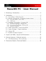
1
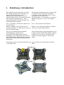
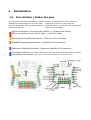
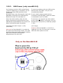
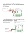
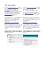
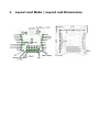
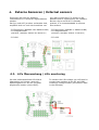
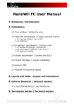
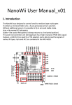
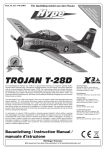
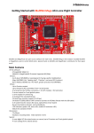
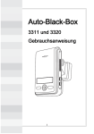
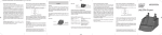
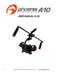
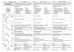
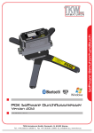
Version 1.1
NanoWii FC - User Manual
1. Einleitung | Introduction......................................................2
2. Installation........................................................................ 3
2.1. Pins Anlöten | Solder the pins...............................................3
2.2. Wahl der Stromquelle | Chooseing a power source...................4
2.2.1. Lipo oder Steller | LiPo or ESC................................................4
2.2.2. USB Power...........................................................................5
2.3. Empfänger anschließen | Connect a RX...................................6
2.3.1. Standard Empfänger | Standard RX.........................................6
2.3.2. Summsignal Empfänger | PPM sum RX.....................................7
2.3.3. Spektrum Satellite................................................................7
2.4. Steller anschließen | Connect the ESCs...................................8
2.5. Copter Montage | Copter installation.....................................9
2.6. Arduino IDE......................................................................10
2.7. MultiWii Firmware & upload.................................................11
3. Layout und Maße | Layout and Dimensions...........................12
4. Externe Sensoren | External sensors...................................13
4.1. LiPo Überwachung | LiPo monitoring.....................................13
5. Technische Details | Technical Details..................................14
1.
Einleitung | Introduction
Das NanoWii wurde entworfen um kleine
bis mittelgroße Multirotor Helikopter zu
steuern. Es verfügt über einen
Mikrocontroller (Prozessor), einem 3Achsen Kreisel (Gyro) und einem 3-Achsen
ACC (Beschleunigungssensor). Ohne
weitere Sensoren ist so der Flug im acro
und stable Modus möglich.
The NanoWii was designed to controll small
to medium sized multirotor helicopters.
It contains a microcontroller unit, a 3-axis
gyroscope and a 3-axis ACC
(accelerometer). It is possible to fly without
additional sensors in “acro” and “stable”
mode.
Acro = Kunstflug (verhält sich ähnlich wie
ein Helikopter)
Stable = Stabiler flug (ähnlich wie ein
koaxial Helikopter => fällt immer zurück in
eine horizontale Lage).
Acro = like normal RC helicopters
Der hier verwendete Mikrocontroller
(ATmega32U4) verfügt über 6
hochauflösende PMW (Steller Signal)
Ausgänge, einen USB Anschluss (es wird
kein FTDI Adapter benötigt) sowie über die
Möglichkeit verschiedene Empfängertypen
auszulesen.
The microcontroller used (Atmega32u4) has
6 high-resolution PWM (ESC signal) outputs,
a USB Port (no need for a FTDI) and the
ability to read the signals of various RX
types.
Stable = like coaxial helicopters (it always
returns to a horizontal position)
Die Sensoren (Gyro und ACC) befinden sich Gyro and ACC are combined in the MPUin der MPU-6050
6050.
2.
Installation
2.1. Pins Anlöten | Solder the pins
Zu erst sollte man sich entscheiden, welche
Anschlüsse man braucht. Es ist nicht nötig
alle Pins anzulöten. So kann man Gewicht
und Arbeit sparen.
First you should decide, which pins you
need. Not all pins are required to be
soldered. That way you can save weight and
time on the helicopter
Steller Anschlüsse (von links nach rechts => Quadro oder Hexa)
ESC's connections (from left to right => quad or hexa)
Summsignal Empfängeranschluss | PPM sum RX connection
Standard Empfängeranschlüsse | Standard RX connections
Spektrum Satellite Anschluss | Spektrum Satellite RX connection
Lipo Akku Anschluss (nur wenn die Steller nicht als Stromversorgung dienen sollen)
Lipo battery connection (only if you don't want the ESCs to be the power source)
2.2. Wahl der Stromquelle | Chooseing a power source
2.2.1.
Lipo oder Steller | LiPo or ESC
Es gibt 3 Möglichkeiten das NanoWii mit
Strom zu versorgen.
There are 3 ways to power the NanoWii
board.
1. Standard: Stromversorgung direkt über
den LiPo Akku. Verbinden sie dafür + und –
des LiPo Akkus mit den dafür vorgesehenen
Pins (siehe Bild)Es können 2S-3S (5-16V)
Lipo akkus angeschlossen werden.
Bei dieser Möglichkeit wird kein BEC der
Regler benötigt.
1. Default: The board is powered by a LiPo
battery on the specified pins (see image)
you can connect a 2S or 3 S (5-16V) LiPo.
In this case there are no ESC BEC needed.
2. Versorgung über ein Regler BEC:
Verbinden sie dafür den Jumper 2 (JP2) mit
einer Lötbrücke (siehe Bild).
2. Power supply by a ESC BEC (or UBEC):
To use a 5V ESC BEC/UBEC you will need to
solder the jumper 2 (JP2) (see image).
ATTENTION !
If jumper 2 is soldered, don't connect a LiPo
battery directly to the board!
ACHTUNG:
Wenn Jumper 2 (JP2) gebrückt ist, darf auf
keinen Fall ein LiPo Akku direkt an das
Board angeschlossen werden!
3. Versorgung über VCC:
Wenn der Empfänger über eine Stromquelle
mit einer Spannung von 5 – 5,5V betrieben
wird, kann das Board auch einfach über den
VCC Pin des Gassteckers verbunden
werden. Bitte lassen sie in diesem Fall
Jumper 2 (JP2) unverbunden.
3. Supplied by VCC:
If your RX is already powered by 5 – 5.5V
you can power the board by the VCC pin of
your RX (throttle connector). In this case
please leave jumper 2 (JP2) open.
2.2.2.
USB Power (only nanoWii 0.5)
Um Probleme mit der USB und der Board
-internen Spannung zu vermeiden, ist der
Pluspol von dem USB Anschluss nicht
verbunden.
So muss immer eine Stromquelle (Lipo oder
ESC/BEC) verbunden sein während das
Board mit einem PC verbunden ist.
To prevent problems with the USB and the
board power, the USB's +5V pin is not
connected by default.
Wenn Sie sicher stellen, dass nie eine
andere Stromquelle gleichzeitig mit dem
USB Stecker angeschlossen ist, können sie
diese Verbindung wieder herstellen.
To ensure to not connect any other power
source while the USB is connected, you can
activate the USB power by soldering jumper
1 (JP1).
Verbinden Sie dafür Jumper 1 (JP1)
(siehe Bild)
(see image)
So you need to have a power source
connected (LiPo ESC/BEC) while the board
is connected to a PC via USB.
Attantion! On the NanoWii 1.0 the JP1 is
Achtung! Auf dem NanoWii 1.0 wurde der
replaced by a fuse. Its now save to use the
JP1 durch eine Sicherung ersetzt. Der USB USB with other power sources.
anschluss kann also immer genutzt werden,
egal ob eine andere Stromquelle
angeschlossen ist oder nicht.
Only on the NanoWii 0.5!
2.3. Empfänger anschließen | Connect a RX
2.3.1.
Standard Empfänger | Standard RX
Ein normaler 4-6 Kanal Empfänger ist
ausreichend. Fünf (5) Kanäle sind aber
empfehlenswert.
You can use a standard RX with 4-6
channels. A RX with a minimum of available
5 channels is recommended .
Es werden nur beim Gaspin alle 3 Kabel
(Signal, plus, minus) angeschlossen. Die
anderen Kanäle brauchen nur das
Signalkabel.
Only for the throttle all three wires are
connected (signal and power (+/-). For the
other channels only the signal wires are
needed.
2.3.2.
Summsignal Empfänger | PPM sum RX
Über einen Summsignal-Empfänger können
bis zu 8 Kanäle mit nur einem Kabel
genutzt werden.
With a PPM sum RX you can use up to 8
channels with only one wire
(Siehe Anschuss-Diagram)
2.3.3.
Spektrum Satellite
Ein Spektrum Satellite Empfänger kann wie
der Summsignal Empfänger bis zu 8 Kanäle
über nur eine Leitung übertragen. Er ist
außerdem sehr klein und leicht.
(Der Satellite muss vorher an einem
Empfänger gebunden werden)
With a Spektrum Satellite RX you can also
use up to 8 channels. It is quite small and
lightweight.
(The Satellite must be bound using another
RX before you can use it)
2.4. Steller anschließen | Connect the ESCs
Am NanoWii ist der Anschluss von bis zu 6
Stellern vorgesehen. Es können jedoch bis
zu acht (8) angeschlossen werden.
Die dargestellten Pins entsprechen hier der
Motorenanordnung und Drehrichtung
The NanoWii was designed to provide up to
6 ESC connections, but by using the
additional pins A2 and 4, up to 8
ESCs/motors are possible.
The images show the motor's positions and
spin directions.
2.5. Copter Montage | Copter installation
Bei dem Einbau des NanoWii ist darauf zu
achten, dass es so mittig wie möglich am
Copter angebracht wird.
When installing the NanoWii it is best placed
at the center of your copter.
2.6. Arduino IDE
Arduino (http://www.arduino.cc) ist eine
Open Source Software, die gemacht ist um
den Umgang mit bestimmten AVR
Mikrocontrollern zu vereinfachen.
Es ist geeignet um C-code zu editieren, und
aufzuspielen.
Das NanoWii wird mit einem Arduino
Leonardo bootloader geliefert, da der
Arduino Leonardo den gleichen
Microcontroller verwendet.
Arduino (http://www.arduino.cc) is a open
source software that is designed to simplify
the use of some AVR MCU's.
It is used to edit and upload C-code.
Das NanoWii sowie auch der Leonardo wird
erst ab Version 1.0.1 unterstützt. Es
empfiehlt sich also immer die Neuste
Arduino Version zu verwenden.
NanoWii and the Leonardo are supported
with the latest Arduino version. (1.0.1 or
later). Always use the latest release of the
Arduino software.
Download:
http://arduino.cc/en/Main/Software
Download:
http://arduino.cc/en/Main/Software
Nach der Installation von Arduino kann der
Treiber für das NanoWii (Arduino Leonardo
Treiber) in dem Installationsverzeichniss
von Arduino unter „drivers“ gefunden
werden.
After installing the Arduino software, you
need to install a driver for the NanoWii
(Arduino Leonardo Drivers) that you can
find it in the Arduino installation folder, in
the “drivers” subfolder.
Um das NanoWii in Arduino auszuwählen,
wählen Sie unter Tools → Board den Arduino
Leonardo und unter Tools → Serial Port den
installierten COM-Port.
To use the NanoWii you need to select the
Arduino Leonardo (Tools → Board → Arduino
Leonardo) and select its COM-port (Tools →
Serial Port)
The NanoWii comes preloaded with the
latest Arduino Leonardo bootloader. This is
possible because it uses the same MPU.
2.7. MultiWii Firmware & upload
MultiWii (http://www.multiwii.com) ist eine MultiWii (http://www.multiwii.com) is an
Open Source Multirotor Helikopter Software open source multirotor heli software by
von Alexandre Dubus.
Alexandre Dubus.
Das NanoWii ist extra für diese Software
ausgelegt.
The NanoWii is specifically designed for the
use with the MultiWii-Software.
Laden Sie die aktuellste Software herunter
(Das NanoWii wird ab der Dev Version vom
06.06.2012 (2.01) voll unterstützt).
Download the latest version of the MWSoftware (the NanoWii is full supported with
the dev version 06.06.2012 (2.01))
download:
download:
http://code.google.com/p/multiwii/downloads/list
http://code.google.com/p/multiwii/downloads/list
Öffnen Sie diese Datei (*.ino) in Arduino
und stellen Sie in der Datei config.h
(vorletzter Tab rechts) das NanoWii, sowie
alle anderen gewünschten Funktionen ein.
Open the script (*.ino) with the ArduinoSoftware and select the NanoWii and make
other changes needed in the file config.h.
Wenn alle Einstellungen vorgenommen
wurden, klicken Sie auf
(Upload) um die Firmware
aufzuspielen
If all settings are right, press the
upload button.
3.
Layout und Maße | Layout and Dimensions
4.
Externe Sensoren | External sensors
Es können alle von der Software
unterstützten I²C Sensoren angeschlossen
werden.
Da Gyro und ACC ja schon vorhanden sind,
empfiehlt sich nur noch der Anschluss von:
You may connect any I²C sensor to the
NanoWii that is supported by the software.
But as a Gyro and a ACC is already
present, it is recommendable to connect
this sensors:
- I²C Barometer (BMP085 oder MS561101BA) - I²C Barometer (BMP085 or MS561101BA)
- I²C Magnetometer
- I²C Magnetometer
(HMC5843, HMC5883, AK8975 oder MAG3110)
- I²C GPS
(HMC5843, HMC5883, AK8975 or MAG3110)
- I²C GPS
4.1. LiPo Überwachung | LiPo monitoring
Um den Ladezustand des LiPo Akkus
überwachen zu können, muss ein
Spannungsteiler an Pin A3 und GND
angebracht werden (siehe VBAT).
To monitor the LiPo voltage you will need to
connect two resistors to pin A3 and GND,
creating a voltage divider (see section VBAT
in the software)
5.
Technische Details | Technical Details
Power Input:
• RAW (LiPo) 2-3S (5-16V)
• VCC 3,3 – 5,5V
Power Output:
• - VCC 5V max. 100mA (Nanowii 0.5)
• - VCC 5V max. 300mA (Nanowii 1.0)
• - 3,3V max. 100mA
Prozessor:
• Atmel ATmega32u4 MU
• 16Mhz
• 32 kB Flash
• 2.5 kB SRAM
• 1kB EEPROM
• Datenblatt http://www.atmel.com/Images/doc7766.pdf
Gyro & ACC:
InvenSense MPU-6050
Datenblatt:
http://www.invensense.com/mems/gyro/documents/PS-MPU-6000A.pdf
USB Anschluss:
Mini USB
The Spektrum brand is a trademark of Horizon Hobbies USA.
Vorbehalt | Disclaimer:
Dieses Dokument wurde als Referenz fuer den
“Flyduino” erstellt, und erhebt keinerlei Anspruch
auf Korrektheit und/oder Vollständigkeit. Beim
Umgang mit elektrischen und eletronischen
Bauelementen sollten stets die ensprechenden
Vorsichtsmassnahmen getroffen werden.
Die MultiWii Software wurde unter the GPL
veroeffentlicht.
Revisions:
v1.0: 20120601 Felix created document
v1.1: 20120625 Axel updated ODT format
v1.2 20130303 Felix Updated with Nanowii 1.0
This is a reference document for the Flyduino flight
controller and does not claim to be correct nor
complete. When handling electrical or electronic
elements please always use safe practices.
The MultiWii software was released under the GPL
license.