1
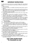
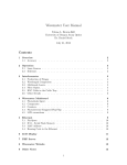
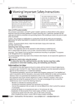
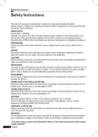
GWY-610
(Ethernet Gateway)
USER’S MANUAL
COPYRIGHT NOTICE
This manual is a publication of Renu Electronics Pvt. Ltd. and is provided for use by its customers only.
The contents of the manual are copyrighted by Renu Electronics Pvt. Ltd.; reproduction in whole or in part, for use
other than in support of Renu Electronics Pvt. Ltd. equipment, is prohibited without the specific written permission
of Renu Electronics Pvt. Ltd..
SERVICE
If service is required then pack the unit in its original packaging container or, if unavailable, any suitable rigid
container. If a substitute container is used, surround the unit with shock absorbing material; damage in shipment
is not covered by the warranty. Include a letter with the unit describing the difficulty and Hardware Revision and
Software Version. Send to the following address:
Renu Electronics Pvt. Ltd.
Survey No. 2/6,
Baner Road,
Pune-411045
India
All returns will be tested to verify customer claims of noncompliance with the product warranty. Improper return
packaging, which makes verification impossible, will void the warranty. If noncompliance is verified and is not due
to customer abuse or the other exceptions described with product warranty, Renu Electronics Pvt. Ltd. will, at its
option, repair or replace the Product returned to it, freight prepaid, which fail to comply with the foregoing
warranty, provided Renu Electronics Pvt. Ltd. is notified of such noncompliance within the one-year warranty
period.
ASSISTANCE
This manual is designed to provide the necessary information for trouble-free installation and operation of your new
Gateway product. However, if you need assistance, please call Renu Electronics Pvt. Ltd. at 91-20-27292840 or
visit our web site at www.renuelectronics.com
MANUAL REVISION
If you contact us in reference to this manual, please include the following document number
Name
:
Ethernet Gateway (GWY-610) User’s Manual
Part Number
:
URML207
Document
:
UMAN\GWY-610\1106
Revision
:
Revision 1
Revision Number
Date
Description
Revision 0
14/02/2007
First release
Revision 1
28/02/2007
----
Revision 2
12/12/2011
System requirement for gateway setup software
revised.
Warranty Certificate
For New product: This product is warranted against defects in materials and workmanship for a period of 12
months from the date of shipment to Buyer.
For Rectified Products: Any product that will be replaced will have Warranty for 6 months or upto Original Product
Warranty period whichever is greater.
The warranty is limited to repair or replacement of the defective unit at the option of the manufacturer. This warranty is void if the product has been altered, misused, dismantled, or otherwise abused.
ALL OTHER WARRANTIES, EXPRESSED OR IMPLIED, ARE EXCLUDED, INCLUDING BUT NOT LIMITED TO
THE IMPLIED WARRANTIES OF MERCHANTABILITY AND FITNESS FOR A PARTICULAR PURPOSE.
MAINTENANCE & SERVICE : There are no parts that can be serviced by the user. Service should be performed
on a unit substitution basis only. Do not attempt to remove, replace or service any printed circuit board, components or any hardware/software related with display product. If problem within the display product occurs, contact
the factory for service information or repair.
NOTE : Renu Electronics Pvt. Ltd. is dedicated to providing complete customer service and customer satisfaction.
If you have any comments or criticisms about how to improve the product features/reliability, Please make a note
of the problem/improvement and notify us. We are always open to new ideas and improvements. So please let us
know your ideas and comments.
IMPORTANT
Gateway Products are intended to be Protocol Converters/Data Sharer devices
that can also take control actions on request of device being connected. It is assumed that
user is well acquainted with the PLC / Inverters / Controllers being used.
Any Mechanical or Electrical Modification to this Unit will void
all Warranties.
Contents
INTRODUCTION
1.1
1.2
1.3
Purpose of this manual
Introduction to Gateway
GWY-610 Specifications
HARDWARE
2.1
2.2
2.3
Dimensional details And Mounting Instructions
Communication Port Details
LED Status
GETTING STARTED
3.1
3.2
3.3
3.3.1
3.4
3.5
Gateway Modes
Master-Master Configuration
Master-Slave Configuration
Repeat Cycle
Control Word
Error Indication Bit
Communication Parameters
Default Communication Registers
Recipes
I/Os
NOTE ON COMMUNICATION DRIVERS
5.1
5.1.1
5.1.2
5.1.3
5.1.4
5.1.5
5.1.6
Note On Communication Drivers
How Modbus TCP server driver works?
How Modbus TCP Client driver works?
How other serial drivers work?
What is IDB (Internal Data Base)?
How does Pass Through work?
Control Word for IDB
TYPICAL PROJECTS
6.1
6.1.1
6.1.2
System Requirements
Installation Instruction
CABLE DIAGRAMS
8.1
8.2
8.3
9
10
11
12
14
19
20
20
22
23
24
24
25
25
26
27
29
30
30
30
31
31
32
33
34
Project Setup
35
Connect Toshiba (link port protocol) PLC (e.g. T1, T2) as Modbus TCP
Server on Ethernet Network
36
Connect Toshiba (link port protocol) PLC (e.g. T1, T2) as Modbus TCP
Client on Ethernet Network:
39
CONFIGURATION SOFTWARE
7.1
7.2
7
7
8
Introduction to GWY-610
15
GWY-610 Configuration
15
Configuration of GWY-610 (IBM Download)
15
When GWY-610 can accept configuration?
16
Quick Start To Ethernet
16
GWY-610 functionality and corresponding LED behaviour for different
phases of GWY-610
17
GWY-610 FEATURES
4.1
4.1.1
4.1.2
4.2
4.3
4.4
4.5
4.6
4.7
4.8
6
OMRON CQM/CPM CMOS PORT TO GWY-610 (EC-P-006A-00)
OMRON CQM1 PLC TO GWY-610 (EC-P-006B-00)
A B SLC DF1 PORT TO GWY-610 (EC-P-027B-00)
Doc No: UMAN\GWY-610\1106
REVISION 0
43
44
44
45
46
47
48
4
8.4
8.5
8.6
8.7
8.8
8.9
8.10
8.11
8.12
8.13
8.14
TOSHIBA T1 LINK PORT TO GWY-610 (EC-P-046A-00)
49
TOSHIBA T1 PLC TO GWY-610 (EC-P-019A-00)
50
TOSHIBA T2 LINK PORT TO GWY-610 (EC-P-046B-00)
51
TOSHIBA T2 PLC TO GWY-610 (EC-P-019B-00)
52
TOSHIBA VF-S11 TO GWY-610
53
NS TO GWY-610
54
THOMSON TECHNOLOGY CONTROLLER TO GWY-610 (EC-P-117-00) 55
OPTOMUX TO GWY-610
56
ETHERNET CABLE
56
YOKOGAWA CONTROLLER TO GWY-610
57
IBM CABLE
58
Doc No: UMAN\GWY-610\1106
REVISION 0
5
Introduction
INTRODUCTION
In this chapter. . . .
♦
Purpose of this manual
♦
Introduction To Gateway
♦
GWY-610 Specifications
Doc No: UMAN\GWY-610\1106
REVISION 2
6
Introduction
1.1
Purpose of this manual
Thank you for purchasing GWY-610 Product from Renu Electronics Pvt. Ltd..
The intention of this User Manual is to provide a guide for Safe installation, Configuration and operation of GWY610-B or GWY-610-G.
Functionality of all the Gateway models is same. Read this User manual thoroughly before installing and
operating GWY-610. This document is based on information available at the time of its publication. While efforts
have been made to be accurate, the information in this document may not cover all the details or variations in
hardware or software. Features described herein may not be present in all hardwares. Renu Electronics Pvt. Ltd.
reserves the right to update information in this publication without prior notice.
1.2
Introduction to Gateway
Gateway is a Protocol Converter / Data sharer for devices like PLCs, inverters (Adjustable Speed Drives), and
other Controllers. Gateway has two serial ports that connect with two different devices. These devices share data
through Gateway. Gateway communicates with a device to get the information required by the device connected on
the other port. The device that requires data is called Destination Device and the device that provides data is called
Source Device. Information could be,
- value of a PLC register.
- status of a PLC coil.
- Command from Source Device to Destination Device to perform any action at the destination end.
Configuration Of Gateway
Note: Please refer ‘IBM Download’ in section 3.4.
Normal Operation:
Modbus TCP Client / Server
Serial Port
PLC 1
Pass Through Port
HMI
Connect Modbus TCP devices to Gateway via Ethernet port and serial device (PLC or Inverter) via PLC’s communication port (correct cables are required) and PLCs can easily exchange information through Ethernet. At the
same time local HMI can communicate with PLC connected on serial port.
Doc No: UMAN\GWY-610\1106
REVISION 2
7
Introduction
1.3
GWY-610 Specifications
Power
LED’s
Communication Ports
:
:
:
24 V DC, 2.5 W
16 LED’s for status indication
3 Communication ports with
COM1 :
RS232 / RS422 / RS485 / CMOS
COM2 :
ETHERNET
COM3 :
RS232
(Isolation between communication ports and Power supply, through DC-DC coupler is 1 KV)
COM1 / PLC1
:
Connects to PC for setup download or connects to PLC1 at
runtime.
COM2 / PLC2
:
***Connects to PLC2 at runtime
COM3 (Pass Through for COM1):
*SCADA or local HMI can be connected
(Isolation between COM 1 and COM2 communication ports, through Opto-isolation is 1KV rms for 1 min
Isolation between COM 3 and COM2 communication ports, through Opto-isolation is 1KV rms for 1 min)
**Digital Inputs
:
**Digital Outputs
:
**I/O Terminals
Ethernet Baud Rate
Operating Temperature
Storage Temperature
Humidity
Mounting
Dimensions (DIN rail)
Weight
Certifications
Immunity to ESD
Immunity to Transients
Immunity to Radiated RF
Immunity to Conducted RF
Emissions
:
:
:
:
:
:
:
:
:
:
:
:
:
:
0 to 5 V DC low
12 to 28 V DC high
Relay Outputs
230VAC; 2Amp/30VDC; 2Amps
Coil voltage 24VDC
Pluggable Terminals
10/100 Mbps (Autodetect)
0o to 60oC
-20o to 80oC
10% to 90% (Non condensing)
DIN rail or back panel mounting
100mm(L) X 35mm(D) X 70mm(W)
200 gm approx.
CE with UL certification
Level 3 as per IEC1000-4-2
Level 3 as per IEC1000-4-4
Level 3 as per IEC1000-4-3
Level 3 as per IEC1000-4-6
EN55011 CISPR A
*Note: For more details on pass through, please refer section, Note on communication drivers
**Note: Not all models support digital I/Os.
***Note: ARP, RARP, IP, TCP, UDP Protocols are supported.
At application layer Modbus TCP server and Modbus TCP clients are supported at present.
New protocols based on tcp and udp are constantly added (e.g. ethernet ip). Contact factory for more
information.
Doc No: UMAN\GWY-610\1106
REVISION 2
8
Hardware
HARDWARE
In this chapter. . . .
♦
Dimensional Details And Mounting Instructions
♦
Communication Port Details
♦
LED Status
Doc No: UMAN\GWY-610\1106
REVISION 2
9
Hardware
2.1
Dimensional details And Mounting Instructions
GWY-610-B unit can be shipped with a separate DIN rail plate which can be attached to the unit, if desired. User
can use the unit with or without the DIN rail plate. Following sketch shows dimensional details of Gateway with the
DIN rail plate.
00
100.00
70.
35
.00
Follow instructions given below:
1. Attach the DIN rail plate to the unit using the clamps on the DIN rail plate.
2. Pull out the clip of the plate.
3. Put the unit on the DIN rail.
4. Push the clip in to secure the unit on the DIN rail.
Doc No: UMAN\GWY-610\1106
REVISION 2
10
Hardware
2.2
Communication Port Details
GWY-610 has three communication ports COM1, Ethernet and Pass Through Port. COM1 port is compatible to
RS232/ RS422/ RS485 and CMOS signal levels. Pinout of this port is given as follows:
PLC1 / COM1
5
RX- (RS422/RS485)
TX- (RS422/RS485)
TXD (CMOS)
+5VDC*
(DO NOT USE)
9
9
8
7
6
6
5
4
3
2
1
1
Signal Ground
RX+ (RS422/RS485)
RXD (RS232C/CMOS)
TXD (RS232C)
TX+ (RS422/RS485)
DB9 Female
*Do not use pin no. 6 of PLC1 / COM1.
**Refer our website (www.renuelectronics.com) for your specific Cable requirements
Pass Through Port:
Ethernet Port:
Signal
Pin
Signal
1
Twisted Pair Transmit Output (Positive)
1
TXD
2
Twisted Pair Transmit Output (Negative)
2
RXD
3
NC
3
SG
4
NC
4
NC
5
NC
5
NC
6
NC
6
NC
7
Twisted Pair Receive Input (Positive)
7
NC
8
Twisted Pair Receive Input (Negative)
8
NC
GWY-610-B
OK
COM1 ETHERNET PASS
THROUGH
24V
DC+
24V
DC-
Pin
COM1 (RS232/RS485/CMOS)
ETHERNET
Pin1
Doc No: UMAN\GWY-610\1106
REVISION 2
PASS THROUGH
(RS232)
Pin1
11
Hardware
2.3
LED Status
There are 13 LEDs for status indication.
LED
OK
Green
Red
COM1
Green
Red
ETHERNET
Green
Red
Pass Through
X0
X1
X2
X3
Y0
Y1
Green
Green
Green
Green
Green
Green
Green
OFF
No Firmware
Flashing
*IBM Download
ON
Communication OK
OFF
Configuration Ok
ON
Configuration Fault
OFF
No data received on COM1 Port
Flashing
Receiving data on COM1 Port
ON
-
OFF
No error in COM1 attach or while block execution
Flashing
-
ON
PLC1 attach error or error while block execution
OFF
Connection is not open with server
ON
Connection is open with server
OFF
No IP conflict
ON
IP conflict or Modbus TCP server not attached
OFF
No data received on Pass Through Port
Flashing
Receiving data on Pass Through Port
ON
-
OFF
Digital input 0 is ON
ON
Digital input 0 is OFF
OFF
Digital input 1 is ON
ON
Digital input 1 is OFF
OFF
Digital input 2 is ON
ON
Digital input 2 is OFF
OFF
Digital input 3 is ON
ON
Digital input 3 is OFF
OFF
Digital output 0 is ON
ON
Digital output 0 is OFF
OFF
Digital output 1 is ON
ON
Digital output 1 is OFF
Table continued on next page....
Doc No: UMAN\GWY-610\1106
REVISION 2
12
Hardware
Y2
Y3
Green
Green
OFF
Digital output 2 is ON
ON
Digital output 2 is OFF
OFF
Digital output 3 is ON
ON
Digital output 3 is OFF
*Note: For more information, please refer section 3.3.1.
For more information on LED behaviour, refer section 3.5.1
Not all models support I/Os and respective LED’s
Doc No: UMAN\GWY-610\1106
REVISION 2
13
Hardware
GETTING STARTED
In this chapter. . . .
♦
Introduction To GWY-610
♦
GWY-610 Operation
♦
Quick Start To Ethernet
♦
GWY-610 Function
Doc No: UMAN\GWY-610\1106
REVISION 2
14
Hardware
3.1
Introduction to GWY-610
GWY-610 is a communication bridge between Ethernet interface on one side and various serial protocols on the
other side. GWY-610 allows serial devices to act as Modbus TCP Client or Modbus TCP slave on Ethernet.
On COM1 side it supports serial protocols (e.g. Modbus Master, Modbus Slave) and on COM2 side it has Modbus
TCP Client and Modbus TCP Server.
COM3 port acts as pass through for COM1*.
GWY-610 is externally powered from 3 pin terminal block and power is isolated from communication ports. Both
the communication ports are also isolated from each other.
It has three communication ports, one with Ethernet interface (10/100 Mbps) and one serial port with RS232 /
RS422 / 2 or 4 wire RS485 (300 to 115.2K), second serial port with RS232 (300 to 115.2K)
*Note: For more details on pass through …please refer to section 5.1.5
3.2
GWY-610 Configuration
GWY-610 can communicate with serial and Ethernet devices using appropriate cables and configuration.
Microsoft Windows® based configuration software, Gateway Setup, configures the GWY-610 unit.
‘Configuration’ means making the GWY-610 unit work as per user application.
Complete configuration for a GWY-610 using the Gateway Setup is termed as a ‘Project’. A Project consists of
Devices to be attached on two ports, Communication settings for two ports to communicate with two devices,
Register addresses for data transfer, Conditions for data transfer etc.
GWY-610 can now communicate with the specified devices without any change in the GWY-610 hardware. To
communicate with a device, GWY-610 needs Communication Drivers for the devices and ‘Gateway - Device’
communication cables.
Each Device has a unique and predefined protocol for communication. GWY-610 driver has this protocol to
communicate with the desired device. As two devices are connected on GWY-610, it requires two drivers for
communication
3.3
Configuration of GWY-610 (IBM Download)
User MUST download Firmware, Project, PLC1 driver and PLC2 driver in Gateway before installing any systemusing Gateway. User needs a special IBM download cable for downloading configuration in Gateway. All
configurations can be downloaded only form Serial port (Port 1).
If any change in the current / working project is made, user must download the changed project in Gateway
DB9 Male (Gateway)
DB9 Female (IBM)
2
2
3
3
5
5
1. For downloading Firmware,drivers and project switch off the GWY-610 unit.
2. Power ON the unit again.Ok LED starts blinking. This means that unit is in download mode.
3. For the first time download all firmware, drivers and project.
IMPORTANT NOTE:
AS GATEWAY HAS MULTIPLE SIGNALS ON ITS COMMUNICATION PORTS, IBM CABLE FOR GATEWAY MUST
HAVE ONLY THREE RS232 SIGNALS (TXD, RXD AND GND) AS MENTIONED ABOVE.
9-9 PIN CORE CABLE SHOULD NOT BE USED.
If you are using USB to serial converter then please connect IBM cable to serial port of converter
Doc No: UMAN\GWY-610\1106
REVISION 2
15
Hardware
3.3.1
When GWY-610 can accept configuration?
If current driver present for PLC1 port is Master (e.g. Modbus (Gateway as master))
First, it is checked that whether device is connected on port1
If device is connected, it continues normal operation
If device is not connected, it checks for IBM download mode for 10sec.
This sequence continues until either is satisfied.
If current driver present for PLC1 port is Slave (e.g. Modbus (Gateway as Slave))
If Port1 of Gateway is Slave, all the configurations should be downloaded Only once for 10sec at power on.
Note: Make sure that OK LED is blinking when you start downloading the configuration in Gateway.
3.4
Quick Start To Ethernet
This section provides quick example on how to get Ethernet running
GWY-610 supports Modbus TCP Client as well as Modbus TCP Server at present.
These settings are for GWY-610
STEP 1 Configure the GWY-610 IP address
User should configure IP address for GWY-610 through Gateway setup software.
PLC2 Settings->Advanced->Extended Setup->IP address
STEP 2 Configure Subnet Mask
User should configure Subnet Mask for GWY-610 through Gateway setup software.
PLC2 Settings->Advanced->Extended Setup->Subnet Mask
Please note that gwy-610 IP address should be unique
STEP 3 Configure Default Gateway Address
User should configure Subnet Mask for GWY-610 through Gateway setup software.
PLC2 Settings->Advanced->Extended Setup->Gateway Address
In case of Modbus TCP Client, some settings additional to above three are required and are as given below:
These settings are for PLCs with which GWY-610 will communicate.
STEP 4 Configure Node address
Node address should be configured through Source address / Destination address through data
exchange blocks
STEP 5 Configure Node Address, IP Address, Port Number
User should configure Node Address, IP Address, Port Number for PLCs with which GWY-610 will communicate,
through Gateway Configuration Software
Settings->Ethernet node table
Note : User can get the Information required for STEP 2 and STEP 3 through PC as follows
(1) Make sure , the PC is connected in Network through Ethernet cable.
(2) Go to command Prompt on PC
Doc No: UMAN\GWY-610\1106
REVISION 2
16
Hardware
(3) Type ipconfig/all
Note :
After the entire configuration is downloaded in GWY-610. And after power on when OK LED is steady, user can
ping the unit with GWY-610’s IP address. If the response is received to the ping command, it means all Ethernet
configuration is correct.
C:\>ping <IP address of GWY-610>
3.5
610
GWY-610 functionality and corresponding LED behaviour for different phases of GWY-
The GWY-610 initialization can be divided into three stages:
1)
Ethernet Initialization Phase
Here baud rate is determined by auto negotiation and IP conflict is checked.
2)
Serial Initialization phase
Here the communication parameters are initialized.
And it’s checked whether the external slave is connected on the port.
3)
Ethernet attach phase
Here it’s checked whether the external server is connected on the port.
The above-mentioned phases are executed sequentially.
‘Ethernet Initialization phase’:
At power on, GWY-610 initializes the Ethernet port. Here the OK LED flashes at faster (relative to the IBM Download mode) rate. While initialization it checks for IP conflict.
If IP conflict occurs; ETHERNET RED LED is lit for a second and then it enters to configuration (download) mode
for 10 seconds. After 10 seconds it again checks for any IP conflicts. This cycle is repeated till the valid configuration with valid IP address is downloaded.
If there is no IP conflict; GWY-610 enters the “Serial Init phase”.
Serial Init phase:
Here the GWY-610 starts scanning nodes that are connected on COM1 port. OK LED is lit green at this time.
If GWY-610 does not get response from COM1 port, it enters in configuration (download) mode.
The OK LED flashes green at this stage. It remains in configuration mode for nearly 10 seconds. The configuration
mode is used for firmware, drivers and project download / upgrade.
After 10 seconds, it again starts scanning for the node. This cycle continues until GWY-610 gets the response from
COM1. Other LEDs will remain off till the cycle is repeating.
After getting response from COM1 port, GWY-610 starts communication on the COMM1 port.
COM1 LED flashes green at this stage and OK LED is steady green.
Now the GW-610 enters the “Ethernet Attach Phase”.
Ethernet Attach Phase:
It starts attaching to Ethernet nodes. Then according to Modbus TCP
Client or Modbus TCP Server driver present in Gateway following is done
(a) In case of Modbus TCP server driver, GWY-610 waits for request from external client.
(b) In case of Modbus TCP client driver, GWY-610 sends request to open connection to external server/s and
wait for the response. If connection is opened successfully; ETHERNET LED will lit green. Otherwise it
Continuously try to open the connection to external server.
Doc No: UMAN\GWY-610\1106
REVISION 2
17
Hardware
Doc No: UMAN\GWY-610\1106
REVISION 2
18
GWY-610 Features
GWY-610 FEATURES
In this chapter. . . .
♦
Gateway Modes
♦
Repeat Cycle
♦
Control Word
♦
Error Indication Bits
♦
Communication Parameters
♦
Default Communication Registers
♦
Recepies
♦
I/Os
Doc No: UMAN\GWY-610\1106
REVISION 2
19
GWY-610 Features
4.1
Gateway Modes
Gateway has two modes of operation: Master-Master and Master-Slave. Before explaining these modes further
Master and Slave concept should be explained.
Master:
Master is a Device / device driver which initiates communication.
Slave:
Slave is Device / Device driver which processes Master’s query, takes necessary action and responds to the query,
if necessary.
4.1.1
Master-Master Configuration
In this mode both Gateway ports are master in nature and devices connected on these ports are slave. Gateway
ports initiate communication when the proper Gateway-Device communication cable is attached. Data is
transferred in blocks.
This transfer can either be a continuous process or as per requirement. A control word , present in device on
either side, enabled from Gateway Setup Software, can control the block execution.
When control word is disabled, then block transfer is a continuous process. A block of data is fetched from one
device and transferred to the other device. The amount of data to be transferred (Number of words) depends on
Block definition in “Block Definition Area” in Configuration Software. One block is executed at a time. A cycle
consists of execution of blocks from #1 to #n.
Execution of blocks is performed as follows:
Block #1
Block #2
Block #3
Block #4
.
.
.
.
.
Block #n
When Control word is enabled, it decides which block has to be executed by writing a specific data in the control
word.
Doc No: UMAN\GWY-610\1106
REVISION 2
20
GWY-610 Features
Let us see the example of Master-Master mode as shown in the picture below:
Configure Gateway ports as:
PLC1 Protocol: Modbus (Gateway as Master)
PLC2 Protocol: Modbus TCP (Gateway as master)
# Words defines number of registers/coils to be read / written between two devices.
Block #1: Gateway reads 10 words starting from 400001 from Modbus and write these 10 words data register
starting from 400001 of Modbus TCP (Gateway as master)
Block #2: Gateway reads 1 word starting from 400020 of Modbus TCP (Gateway as master) and writes it to
holding register 400020 of Modbus (Gateway as master).
As this example has only two blocks, Gateway will execute Block #1 after executing Block #2 continuing this cycle
forever.
Notes:
1) Maximum 255 blocks can be configured in any mode.
Doc No: UMAN\GWY-610\1106
REVISION 2
21
GWY-610 Features
4.1.2
Master-Slave Configuration
In this mode, one of the Gateway ports is a master and other is the slave so the devices connected on these ports
are slave and master respectively. Blocks do not control data transfer in this mode. Data transfer takes place only
when Master Device, connected on slave port of Gateway, sends a request to read / write data. This mode
requires mapping
registers for data transfer. Mapping means defining one or multiple registers in the Slave Device corresponding to
one or multiple registers / coils in the Master Device. Mapping can be done using the Block definition area, so in
this mode, any Block is used for mapping registers of the two devices.
In Block Definition area, # Words Field indicates number of registers to be mapped linearly from the starting
addresses of the Source Device to the Destination Device. Maximum number of registers that can be mapped is
255, but this does not mean that Master Device has to read / write 255 registers in one command.
In one command Master can read / write registers from one Block only, so if multiple registers are to be read /
written using a single command, # Words also limits the maximum number of registers to be read / written.
Number of registers to be read /written in one command also depends on
Protocol of BOTH the devices
Buffer capacity of Gateway.
Now let us take the example of Master-Slave mode.
Configure Gateway ports as:
PLC1 Protocol - Modbus (Gateway as Slave)
PLC2 Protocol – Modbus TCP(Gateway as Slave)
Block #1 maps 10 words of Modbus (Gateway as Slave) starting from 400001 to Modbus TCP (Gateway as
Slave) starting from 400001.
Block #2 maps 12 words of Modbus (Gateway as Slave) starting from O00001 to Modbus TCP (Gateway as
Slave) starting from O00001.
Doc No: UMAN\GWY-610\1106
REVISION 2
22
GWY-610 Features
In above example, request from Modbus Master is executed as follows:
1.
Modbus Master connected on serial port (COM1) sends command to Gateway for setting holding
register 400001.
2.
Gateway searches defined Blocks and checks whether this register is mapped to any Modbus TCP word.
3.
In example, holding register 400001 (Modbus (Gateway as Slave)) is mapped to 400001 (Modbus TCP
(Gateway as Slave)) in Block 1. Gateway accepts this command and sets 400001 (Modbus TCP
(Gateway
as Slave)).
If Master sends a command to read / write a register / coil not defined in any Block then Gateway sends
exception response to master.
NOTES:
1)
If multiple registers are to be read or written in one command, then all the registers have to
be defined in one Block.
2)
As Gateway Setup Software is common for both the Gateway Modes, titles in the Block Definition
Area, may not be appropriate when using Gateway in Master - Slave mode (e.g. Source ID, Source
PLC, Destination PLC).
3)
Maximum 255 blocks can be configured in any mode.
4)
In Master - slave mode, If somebody mapped read only registers at destination end to any
registers at Source end, it’s users responsibility that these registers are not going to be written by
master.
4.2
Repeat Cycle
User can control Block execution by using the Repeat Cycle field. This number decides whether the Block will be
executed in each cycle. Larger the number lower the priority of the Block. Range for Repeat Cycle setting is 1-99.
Repeat Cycle = 1 ………… Highest priority
Repeat Cycle =99 …………Lowest priority
Repeat cycle is important when using Gateway in Master - Master mode. If Gateway is used in Master - Slave
mode, Repeat Cycle field should be kept as ‘1’.
Repeat cycle defines the number of times a Block will be skipped while executing Blocks in a sequential manner.
Block will not be executed for [Repeat Cycle - 1] cycles. So if Repeat Cycle for a Block is 1, it will be executed in
each cycle whereas if Repeat Cycle is 2, then this Block will NOT be executed in alternate cycles.
For example, suppose Blocks are defined with following Repeat Cycles:
Block #1
Repeat Cycle = 1
Block #2
Repeat Cycle = 2
Block #3
Repeat Cycle = 3
Block #4
Repeat Cycle = 4
After power up, Cycles will be executed as follows:
Cycle 1:
Block #1
Block #2
Block #3
Block #4
Cycle 2:
Block #1
Cycle 3:
Block #1
Block #2
Cycle 4:
Block #1
Block #3
Cycle 5:
Block #1
Block #2
Block #4
Doc No: UMAN\GWY-610\1106
REVISION 2
23
GWY-610 Features
4.3
Control Word
Another way of controlling Block execution is by use of the Control Words. 16 control words i.e. 255 control bits
are available by which user can control 255 blocks. Oth Control bit corresponds Oth bit of control word 1, .., 16st
Control bit corresponds 0st bit of control word 2,.. , 255th Control bit corresponds 15th bit of control word 16. By
default 0 to 255 control bits are mapped to 1 to 256 blocks. User can change value of the control bit. Control
Word can be enabled or disabled in Gateway Configuration.
Normally Control Word is disabled for a New project. Just clicking on check box in the setup software can enable
it. Control Word can be chosen from any of the Devices connected.
If the Control Word field is enabled, for the control bit chosen in the project block, accordingly the
number of words in the control field should be taken.
For example, if 36th Control bit is chosen to control the block then number of words in the Control Word field
should be 3.
Number of control bits / 16 = Number of control words.
If Number of control bits % 16 != 0 (Non-zero so add 1 in the number of words in the control field) then Number of
control words = Number of control words + 1
In the above example, number of control bits are 36.
So 36 / 16 = 2 (Number of words in control field)
36%16 = 4 (i.e. Non-zero so add 1 in the number of words in the control field), so number of words in control field
are 2+1 = 3. So number of words in the control field should be chosen as 3. For any block any control bit can be
chosen.
Control Word can only be used in Master-Master mode since no continuous data transfer takes place in Master –
Slave mode (data transfer only takes place on Master’s request)
When the Control Word is disabled, Block execution is totally controlled by Repeat Cycle settings. When the
Control Word is enabled, Block execution is controlled using discrete bits of that word.
○ ○ ○ ○
Bit 0 in control word controls execution of Block #1
Bit 1 in control word controls execution of Block #2
Bit 15 in control word controls execution of Block #16
When a bit is high, ‘1’, corresponding Block is executed depending on its Repeat Cycle. When a bit is low, ‘0’,
execution of corresponding Block is disabled.
4.4
Error Indication Bit
This feature enables detection of communication breaks during error free communication between Gateway and
two devices. Communication breaks can occur due to no cable connection, wire faults, device power failure at
both ends of Gateway. An Error bit can be designated in each external device connected to Gateway. Using this
bit, fault at the PLC1 end can be reported to PLC2 Device and fault at PLC2 end can be reported to
PLC1 Device. When communication error occurs on PLC1, Gateway sets error bit in PLC2 device.
Error Indication Bit can only be used in Master-Master mode. In Master-Slave mode any error can easily be
detected by a communication time out on the Master.
Error indication bit can be enabled using Gateway configuration software. Normally Error bit is disabled for a new
project. Just clicking on the check box in the setup software can enable it. Error indication bit can be enabled in
both or any one of the Devices connected to Gateway. Error Indication bit is “OFF” to indicate error free
communication. In case of communication error on PLC2, Gateway sets error bit on PLC1 port and vice versa.
Note: If error indication bit is a bit of a bit addresable word then don’t use that word in project mapping.
Doc No: UMAN\GWY-610\1106
REVISION 2
24
GWY-610 Features
4.5
Communication Parameters
Communication Parameters of Gateway can be set from configuration Software. This enables Gateway to readily
communicate with any device. Communication parameters for PLC1 and PLC2 ports can be configured
independently. This feature allows changes in Baud rate, Number of stop bits, Parity etc. at any time without
downloading the driver for that particular device. After the driver for a particular device is downloaded, simply
selecting new communication parameters and downloading the same project can change the communication
parameters.
4.6
Default Communication Registers
Purpose:
To provide flexible Attach Sequence.
This register is used to test communication with the device to see if device is connected and to check
if settings are proper.
Location: User can access these register in “Settings>> Default Communication Register” menu.
This feature is useful when external slave device does not allow single read operation or does not
respond to any particular register.
For example: Some energy meters allow reading in multiple of 16 registers only.
Previously for Modbus Driver only holding register 400001 was read for attach. But if a particular
device does not respond to 400001, then the initialization will fail.
What does the “Default Communication Register” do?
After power up default communication register is the first register that is fetched by the master driver from the
slave device. If response for this register is received from slave then only gateway will start the Ethernet
initialization. Otherwise GWY-610 would continuously try to establish the communication with external Slave
device by sending read request with the “default communication register”.
NOTE:
1) This is implemented only for master drivers that support IDB.
2) First register present in first row of IDB is taken as default communication register.
3) The no of words field for default communication register are 1, user can change the value to maximum of 255
whichever is applicable (35 is valid in above case).
Doc No: UMAN\GWY-610\1106
REVISION 2
25
GWY-610 Features
4.7
Recipes
Purpose:
Location:
To provide user-definable write of configuration properties or control sequences at power on to the
external Slave Devices.
User can access these Recipes in “Settings>>Recipes” menu.
In case of some Slaves it is necessary to write configuration properties or control sequences at power on. Drives/
Inverters generally require this kind of sequence.
After power on, before Gateway Project Block execution starts, Recipes blocks will be executed and the specified
value will be written into the specified registers.
NOTE:
1) Recipes are only useful for master drivers.
2) All the fields in Recepies i.e. COM Port, Station ID, #Words, Register Address, Value can be changed by user.
Doc No: UMAN\GWY-610\1106
REVISION 2
26
GWY-610 Features
4.8
I/Os
Four digital Inputs and four relay outputs are provided for GWY-610
CASE a - Operation in case of Modbus TCP Server
(1)
Input Word should be configured as follows
PLC2 settings/Advanced/Extended setup/Input Word
(its input register)
(2)
Output Word should be configured as follows
(its holding register)
PLC2 settings/Advanced/Extended setup/Output Word
(3)
User can read the status of physical inputs in configured Input word i.e. Input Register.
(4)
User can change the status of physical outputs from configured Output word i.e. Holding Register.
Important Note
1.
Input Word and Output Word configured should not be used in actual project.
2.
Input Word reading and Output Word modifying should be done separately. It should not be done with
normal project registers.
Doc No: UMAN\GWY-610\1106
REVISION 2
27
GWY-610 Features
CASE b - Operation in case of Modbus TCP Client
(1)
Internal memory register 25 (IM0025) is used for Input and Internal memory register 26 (IM0026) is used
for Output.
So IM0025 is read-only and IM0026 is write-only.
(2)
While configuring the project user should map Input Word and Output Word to any register of serial
driver.
This way user can access Input Word and Output word
Doc No: UMAN\GWY-610\1106
REVISION 2
28
Note on Communication Drivers
NOTE ON COMMUNICATION DRIVERS
Doc No: UMAN\GWY-610\1106
REVISION 2
29
Note on Communication Drivers
5.1
Note On Communication Drivers
5.1.1
How Modbus TCP server driver works?
(1)
(2)
(3)
A FIFO is maintained for clients. So that when a query from one client is processed, queries from other
clients are accepted and stored.
When the query arrives, its stored in respective buffers. According to the “first come first served “, the
query is processed.
Maximum five clients are allowed in this scheme. If sixth client tries to establish the connection with
Gateway, we do not allow opening the TCP connection. We simply discard the frame.
When the query is received, the client is identified and corresponding FIFO entry is updated.
Here, we just acknowledge the query that we have accepted the query.
After receiving response from serial side, it is sent to TCP client.
When we send the response to particular client, we again update the corresponding FIFO entry.
(4)
(5)
(6)
(7)
(8)
When a particular client is disconnected, the respective client entry is deleted from FIFO as well as
Ethernet TCP structure. Another client is then allowed to communicate in place of previous disconnected
client.
Timeout at the TCP client should be greater than
(Serial timeout * no of retry at serial side * no. Of clients on Ethernet side)
If number of clients are not known, then on safer side assume number Of clients on Ethernet side equal
to 5 and set the timeout.
If timeout is less at TCP client side and before processing the particular query from the client, new query
is arrived from the same client. The previous query is discarded and new is processed.
If serial communication is beaked (due to cable removal or serial device powered off etc), exception is
sent to Ethernet side. The exception code is 0x04(slave device failure)
If a query from certain existing client is not arrived for two minutes, connection is disconnected and new
client is allowed in this place.
Source ID and Destination ID related to Modbus TCP server driver does not have specific meaning.
5.1.2
How Modbus TCP Client driver works?
*While configuring the project, user should give Node ID, IP Address, Communication Port of Modbus TCP
servers with which Gateway Client would communicate. For details refer to section Quick Start( Section 3.4).
IDB is used for Modbus TCP client. Modbus TCP Client can communicate with multiple Modbus TCP servers,
maximum 32.
If connection with any of the servers is failed, the particular server is disconnected regardless of “Skip on
Communication fail” setting in Gateway configuration software.
The only way to re-establish the connection is as follows
(1)
Internal Memory register IM00021 and IM00022 are defined in Modbus TCP Client
(2)
You can map these register to any other register through gateway set up software
(3)
If data in IM00021 data is 0001 then node 1 is reconnected
If in IM00021 the data is 0x02 then node 2 is reconnected and so on.....
(4)
After node reconnection , its user’s responsibility to again make the data in corresponding IM0002x word
as 0x00
*Note: For more details on configuring the project, please refer section 6.1.2
I
IM0
IM15
**Control Word for IDB
IM16
IM20
Reserved
IM21
IM22
Node Reconnection
IM23
IM24
Reserved
IM25
***Input Word
M26
***Output Word
Doc No: UMAN\GWY-610\1106
REVISION 2
30
Note on Communication Drivers
**Note: Please refer section 5.1.6
***Note: Please refer section 4.8
5.1.3
How other serial drivers work?
Example1: Toshiba ASD
In drivers like Toshiba ASD’s, single parameter is read at a time. It does not allow multiple parameters read. So in
case of Toshiba ASD’s driver concept of Internal Database* is not used.
Example2: Toshiba PLC
Since drivers like Toshiba PLC, Modbus allow multiple register reading in one block, in this case concept of
Internal Database* is used.
* Note: Concept of Internal database (IDB) is explained next.
5.1.4
What is IDB (Internal Data Base)?
Internal Data Base is a concept wherein the data for the registers mapped in the project is fetched internally (or to
say in the background) and the values are maintained internally by the Master Drivers.
NOTE: The Internal database is associated only with Master drivers.
Let us have a glance at Internal database.
Please refer the following example: These blocks are uploaded/read in continuous fashion (in the background by
Gateway driver) and data is stored in internal database memory. So time required for read cycle is optimized.
Write operations are on comparison basis.
Since all the registers data is already present in internal database memory of Gateway driver, every time before
performing Write operation data is compared with the internal memory data. In this way unnecessary write
operations can be avoided.
The PLC2 driver uses this data whenever needed according to gateway project.
Every Master driver has its own internal database of 3KBytes. Data fetched by the master driver from external
slave device is loaded into its internal memory in continuous fashion irrespective of block execution of Gateway
project.
“Background communication Enable/Disable” default setting depends on PLC or Device protocol. The speed of
data transfer is improved because of Internal database since it reduces the number of block executions required
by the Gateway software
Background Read OperaWrite OperaWrite in Internal
Gateway
Master
Driver
Slave Device
Modbus
3KBytes
Write in External
Compare
Figure 1 explains the operation of Master-Master mode with background communication.
Doc No: UMAN\GWY-610\1106
REVISION 2
31
Note on Communication Drivers
Advantages of background communication:
1. Better speed: For background communication each master driver has 3K internal memory (i.e. 1500 words). If
background communication is enabled master driver will use inputs from internal database (IDB) and continuously
start-fetching data for defined registers in IDB independent to other side driver. This all data is stored in internal
data memory. When request comes from other end external master for mapped registers in gateway projects then
data is given from internal memory so time for data fetching from slave device is minimized.
If IDB is not present then data is fetched by sending command to slave device and then it is transferred to other
side device, which consumes time, and hence speed is low.
Skip on communication fail:
This feature is very useful when multiple slaves are connected to gateway. This can be settable by user in IDB
setup. This feature will decide to skip data fetching from specific node if that node in the network is off.
If any node is off during normal communication, gateway will skip this node in next data fetch cycle and gives
failure indication by flashing led in RED on master port side (i.e. on COM1 side of gateway) and keep its normal
data fetching from other nodes. If any failed node is again come in the communication network to fetch data from
this node user should have to reset the gateway.
Fail value:
If communication break occurs between external slaves and gateway due power off of any particular slave then
gateway moves specified value in other side mapped register
At power on each master driver will get all inputs from their internal database Setup and according to that
information starts fetching and loading data into its internal database memory irrespective of execution of project
blocks.
The master driver will read all the data and load it into the internal database memory. But in case of write
operation, each master driver will check the data available in the internal memory with the new data to be written.
If the data in the internal memory is same as the new data, then Gateway software will skip the write command. In
case of different data, master driver will initiate the write command.
5.1.5
How does Pass Through work?
Please refer the diagram below:
E
T
H
E
R
N
E
T
COM2
GWY-610-B
COM1
Pass Through
Slave Device
Master Device
Imagine a situation where particular Slave PLC/Inverter/Drive is connected on COM1 and Ethernet on COM2.
Now if the user wants to monitor or change parameters of PLC with keypad or any special device that has same
communication protocol as PLC without disconnecting it from Gateway, then user can use the pass through port.
The pass through port itself is slave port, the device connected on pass through port sends particular request on
pass through port. The request is passed to COM1 port. When device on COM1 port responds then the response
is passed to pass through port.
So in GWY-610, pass through port is for COM1 that has same communication protocol as well as same
communication parameters as COM1
Note: Right now Modbus is implemented on pass through. Contact factory for other protocols.
Doc No: UMAN\GWY-610\1106
REVISION 2
32
Note on Communication Drivers
5.1.6
Control Word for IDB
Purpose: To provide user’s control over the IDB block execution during run time.
16 internal memory registers are added in each master driver (IM0000 to IM0015. Bits of these
registers will control 255 IDB block executions. If bit value is 1 then IDB block will execute and if it is 0
then IDB block will not execute.
Initially at power on all internal memory register will have value 0xFFFF, so all IDB block will execute. After
communication is totally established user can change internal memory data to execute required IDB block.
Why/ when is the “Control Word for IDB” required?
S1
M1
S2
M2
Let us assume the User has defined different Blocks in the Project in Master-Slave Mode that gives rise to 20
blocks in IDB of M1 (as this is a Master Driver). Now if the external Master (M2) requires execution of only few of
those 20 IDB blocks, then using the “Control Word for IDB” user can select only the blocks that need to be
executed currently.
The visible advantage is this will speed up the Block execution and data exchange rate.
This feature is useful in Master-Slave mode.
Doc No: UMAN\GWY-610\1106
REVISION 2
33
Typical Projects
TYPICAL PROJECTS
In this chapter. . . .
♦
Project Setup
Doc No: UMAN\GWY-610\1106
REVISION 2
34
Typical Projects
6.1
Project Setup
This Chapter explains, how a simple Gateway project can be created and tested. To develop a Gateway system,
select appropriate Gateway model depending on the system requirements. A new project can be created as
follows:
1.
2.
3.
4.
5.
6.
7.
8.
9.
10.
Define the Gateway System:
1.1
Protocol of Device(s) connected to PLC1
1.2
Protocol of Device(s) connected to PLC2
Load Microsoft Windows® based Gateway Setup software.
Select devices to be connected on two ports.
Define Blocks for data transfer.
Set the communication parameters for the selected devices.
Set conditions for block execution if required (Repeat Cycle, Control Word etc.)
Apply power to Gateway.
Download the Project and Communication Drivers into Gateway.
Remove Configuration Cable from PLC1 Connect Gateway - Device cable to PLC1
Test system.
Doc No: UMAN\GWY-610\1106
REVISION 2
35
Typical Projects
6.1.1
Connect Toshiba (link port protocol) PLC (e.g. T1, T2) as Modbus TCP Server on
Ethernet Network
1. Launch gateway set-up software.
2. Select “GWY-6XX....” from product list as shown below:
3. After selecting; below given image will appear. Select COM1 and COM2 side protocols and click “Configure”.
Doc No: UMAN\GWY-610\1106
REVISION 2
36
Typical Projects
4. Configure the project as shown below:
5. Set ethernet side settings as shown below:
Doc No: UMAN\GWY-610\1106
REVISION 2
37
Typical Projects
6. Set PLC1 side settings as shown below:
7. Download the configuration in gateway. Select All>>Download
Now your gateway is configured and ready for communication.
Doc No: UMAN\GWY-610\1106
REVISION 2
38
Typical Projects
Following Gateway examples show detailed setup for common Gateway configurations
6.1.2
Connect Toshiba (link port protocol) PLC (e.g. T1, T2) as Modbus TCP Client on
Ethernet Network:
1. Launch gateway set-up software.
2. Select “GWY-6XX....” from product list.
3. Select COM1 and COM2 side protocols and click “Configure”:
Doc No: UMAN\GWY-610\1106
REVISION 2
39
Typical Projects
3. Configure the project as shown below:
4. Set ethernet side settings as shown below:
Doc No: UMAN\GWY-610\1106
REVISION 2
40
Typical Projects
5. Set PLC1 side settings as shown below:
6. Configure ethernet node table as shown below:
Doc No: UMAN\GWY-610\1106
REVISION 2
41
Typical Projects
7. Download the gateway configuration. Select All >>Download:
Now your gateway is configured and ready for communication.
Doc No: UMAN\GWY-610\1106
REVISION 2
42
Configuration Software
CONFIGURATION SOFTWARE
In this chapter...
♦
System Requirements
♦
Installation Instruction
Doc No: UMAN\GWY-610\1106
REVISION 2
43
Configuration Software
7.1
System Requirements
System Requirement for Gateway setup software are:
Windows Version:
Processor:
Hard disk Space:
Serial Mouse:
RAM:
Display resolution:
Display colors:
7.2
Microsoft Windows XP / 2000, Windows 7 / VISTA (32/64 bits)
PENTIUM or higher
5 MB or more
Required
64 MB or more
800 X 600 (VGA) or better
16 bit color
Installation Instruction
Use the following procedure to install the Microsoft Windows® based Gateway setup software This installation
shows the procedure to install the software from a CD Disk on drive E. On machines with different drive configurations, change the names as needed. It is recommended that a backup disk of the Gateway setup software disk be
created and stored in a safe place.
1. Launch the Windows operating system.
2. Insert the setup CD into CD-drive.
3. Point to the start button then click RUN
4. In the command line box enter E:\Disk1\setup.exe. Click OK. This will launch the Gateway installer.
5. Follow the instructions to complete setup.
Gateway Project:
Each Gateway must be configured before connecting it to the PLC. Gateway configuration software allows the
following:
1. Create a new Gateway project
- Select protocols for both communication ports of gateway.
- Create blocks for data to be shared.
- Set Communication Parameters for both the ports.
- Set Control Word. (Optional)
- Set Error Indication Bit, etc. (Optional)
2. Downloading.
- Download Project
- Download drivers
- Download new firmware, if required (only for upgrading).
3. Upload Project.
The existing project in the gateway module can be viewed/edited.
4. Upload System Data.
This option enables viewing of version number, status of firmware, drivers used, and boot block.
Doc No: UMAN\GWY-610\1106
REVISION 2
44
Cable Diagram
CABLE DIAGRAMS
In this chapter...
♦
Communication Cables for GWY-610
♦
IBM Cable for GWY-610
Doc No: UMAN\GWY-610\1106
REVISION 2
45
Cable Diagram
8.1
OMRON CQM/CPM CMOS PORT TO GWY-610 (EC-P-006A-00)
GWY-610 SIDE
OMRON CMOS
SIDE
2 mtr.
TM
UNIT
OMRON
C200H
-CN422
OMRON 20 PIN
CONNECTOR (CMOS)
SIGNALS
RXD
TXD CMOS
SG
DB9 MALE
(CMOS)
Shield Wire
Pin #
Pin #
1
2
3
4
5
6
7
8
9
10
11
12
13
14
15
16
17
18
19
20
1
2
3
RXD
4
5
SG
6
7
TXD CMOS
8
9
Shield Wire
DB9 MALE
PINOUTS
6
9
Doc No: UMAN\GWY-610\1106
REVISION 2
SIGNALS
1
5
46
Cable Diagram
8.2
OMRON CQM1 PLC TO GWY-610 (EC-P-006B-00)
GWY-610 SIDE
OMRON CQM1
SIDE
UNIT
ATTACH
PLC
2 mtr.
DB9 MALE
(RS232)
DB9 MALE
(RS232)
Shield Wire
SIGNALS
SIGNALS
Pin #
Pin #
EARTH
1
1
TXD
2
2
TXD
RXD
3
3
RXD
4
4
5
5
6
6
7
7
8
8
9
9
SG
SG
Shield Wire
DB9 MALE
PINOUTS
6
9
Doc No: UMAN\GWY-610\1106
REVISION 2
1
5
47
Cable Diagram
8.3
A B SLC DF1 PORT TO GWY-610 (EC-P-027B-00)
AB SLC SIDE
GWY-610 SIDE
ATTACH
PLC
DB9 FEMALE
(RS232)
SIGNALS
UNIT
2 mtr.
DB9 MALE
(RS232)
Shield Wire
SIGNALS
Pin #
Pin #
1
1
RXD
2
2
TXD
TXD
3
3
RXD
4
4
5
5
6
6
7
7
8
8
9
9
SG
DB9 FEMALE Shield Wire to DB9 body
PINOUTS
9
6
5
1
Doc No: UMAN\GWY-610\1106
REVISION 2
SG
DB9 MALE
PINOUTS
6
9
1
5
48
Cable Diagram
8.4
TOSHIBA T1 LINK PORT TO GWY-610 (EC-P-046A-00)
GWY-610 SIDE
TOSHIBA T1 LINK
PORT SIDE
WIRE OUTS
SIGNAL FROM PLC
UNIT
2 mtr.
DB9 MALE
(RS485)
Shield Wire
SIGNALS
Pin #
Pin #
SIGNALS
RX+
YELLOW
1
TX+
TX+
GREEN
2
SG
BLACK
3
RX-
WHITE
4
RX+
TX-
BLUE
5
SG
6
7
Shield Wire
8
TX-
9
RXDB9 MALE
PINOUTS
6
1
9
5
Doc No: UMAN\GWY-610\1106
REVISION 2
49
Cable Diagram
8.5
TOSHIBA T1 PLC TO GWY-610 (EC-P-019A-00)
GWY-610 SIDE
TOSHIBA T1
SIDE
2 mtr.
UNIT
MINIDIN 8 PIN MALE
(RS232)
DB9 MALE
(RS232)
Shield Wire
Pin #
Pin #
1
1
2
2
TXD
3
3
RXD
4
4
SG
5
5
TXD
6
6
7
7
8
8
SIGNALS
RXD
SIGNALS
SG
9
Shield Wire
8 PIN MINIDIN CONNECTOR
PINOUTS
6
DB9 MALE
PINOUTS
8
7
5
3
4
6
1
9
1
Doc No: UMAN\GWY-610\1106
REVISION 2
2
5
50
Cable Diagram
8.6
TOSHIBA T2 LINK PORT TO GWY-610 (EC-P-046B-00)
ATTACH PLC
TOSHIBA T2 LINK
PORT SIDE
GWY-610 SIDE
2 mtr.
UNIT
DB15 MALE (RS485)
DB9 MALE
(RS485)
Shield Wire
SIGNALS # Pin #
Pin #
SIGNALS
1
TX+
1
RX+
2
TX+
3
2
4
3
5
6
7
SG
8
9
RX-
10
TX-
11
4
RX+
5
SG
6
7
12
13
8
TX-
9
RX-
14
15
Shield Wire
DB9 MALE
PINOUTS
DB15 MALE
PINOUTS
9
1
6
9
15
1
5
8
Doc No: UMAN\GWY-610\1106
REVISION 2
51
Cable Diagram
8.7
TOSHIBA T2 PLC TO GWY-610 (EC-P-019B-00)
TOSHIBA T2
SIDE
GWY-610 SIDE
ATTACH
PLC
DB9 MALE
(RS232)
SIGNALS
UNIT
2 mtr.
DB9 MALE
(RS232)
Shield Wire
SIGNALS
Pin #
Pin #
1
1
RXD
2
2
TXD
TXD
3
3
RXD
4
4
5
5
6
6
7
7
8
8
9
9
SG
Shield Wire
SG
DB9 MALE
PINOUTS
6
1
9
5
Note: These details are also applicable to Siemens S7-300
Doc No: UMAN\GWY-610\1106
REVISION 2
52
Cable Diagram
8.8
TOSHIBA VF-S11 TO GWY-610
TOSHIBA VF-S11
SIDE
GWY-610 SIDE
8 PIN MODULAR
CONNECTOR (RS232)
SIGNALS
UNIT
2 mtr.
DB9 MALE
(RS232)
Shield Wire
Pin #
Pin #
1
1
SG
2
2
RXD
3
3
4
4
5
5
6
6
7
7
8
8
CMOS TXD
RXD
SG
CMOS TXD
9
Shield Wire
8 PIN MODULAR CONNECTOR
PINOUTS
SIGNALS
R.H.S. VIEW
DB9 MALE PINOUTS
FRONT VIEW
Pin 8
(Right side)
Pin 1
(Left side)
6
1
9
5
Cable insert
end
Doc No: UMAN\GWY-610\1106
REVISION 2
Cable insert
end
53
Cable Diagram
8.9
NS TO GWY-610
NS SIDE
GWY-610 SIDE
UNIT
ATTACH
PLC
2 mtr.
DB9 MALE
(RS232)
SIGNALS
DB9 MALE
(RS232)
Shield Wire
SIGNALS
Pin #
Pin #
1
1
RXD
2
2
TXD
TXD
3
3
RXD
4
4
5
5
6
6
7
7
8
8
9
9
SG
Shield Wire to DB9 body
SG
DB9 MALE
PINOUTS
6
1
9
5
Doc No: UMAN\GWY-610\1106
REVISION 2
54
Cable Diagram
8.10
THOMSON TECHNOLOGY CONTROLLER TO GWY-610 (EC-P-117-00)
GWY-610 SIDE
THOMSON TECHNOLOGY
CONTROLLER
8 PIN MODULAR
CONNECTOR (RS485)
UNIT
2 mtr.
DB9 MALE
(RS485)
Shield Wire
SIGNALS
Pin #
Pin #
SIGNALS
RX+
1
1
TX+
RX-
2
2
TX-
3
3
TX+
4
4
RX+
GND
5
5
SG
6
6
7
7
8
8
TX-
9
RX-
8 PIN MODULAR CONNECTOR
PINOUTS
FRONT VIEW
Shield Wire
R.H.S. VIEW
DB9 MALE
PINOUTS
Pin 8
(Right side)
Pin 1
(Left side)
6
1
9
5
Cable insert
end
Doc No: UMAN\GWY-610\1106
REVISION 2
Cable insert
end
55
Cable Diagram
8.11
OPTOMUX TO GWY-610
5
1
6
9
TX- TX+ RX- RX+
RX- RX+ TX- TX+
8.12
ETHERNET CABLE
Cross-Over Cable Connections
Hook underneath RJ-45s
From Ethernet switch to GWY-610, it should be straight cable and from GWY-610 to PC, it should be cross-over
cable.
Doc No: UMAN\GWY-610\1106
REVISION 2
56
Cable Diagram
8.13
YOKOGAWA CONTROLLER TO GWY-610
YOKOGAWA CONTROLLER
SIDE
GWY-610 SIDE
WIRE OUTS
SIGNAL FROM PLC
UNIT
2 mtr.
DB9 MALE
(RS485)
Shield Wire
SIGNALS
Pin #
Pin #
SIGNALS
RX+
YELLOW
1
TX+
TX+
GREEN
2
SG
BLACK
3
RX-
WHITE
4
RX+
TX-
BLUE
5
SG
6
7
Shield Wire
8
TX-
9
RXDB9 MALE
PINOUTS
6
1
9
5
Doc No: UMAN\GWY-610\1106
REVISION 2
57
Cable Diagram
8.14
IBM CABLE
PC SIDE
GWY-610 SIDE
UNIT
IBM
2 mtr.
DB9 FEMALE
(RS232)
DB9 MALE
(RS232)
Shield Wire
Pin #
Pin #
1
1
RXD
2
2
TXD
TXD
3
3
RXD
4
4
5
5
6
6
7
7
8
8
9
9
SIGNALS
SG
SIGNALS
SG
Shield Wire
DB9 FEMALE PINOUTS
9
DB9 MALE PINOUTS
5
6
6
1
Doc No: UMAN\GWY-610\1106
REVISION 2
1
9
5
58