1
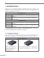
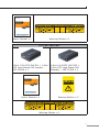
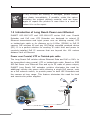
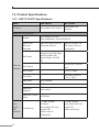
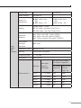
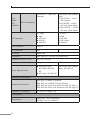
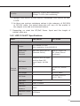
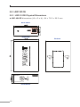
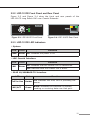
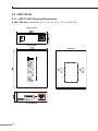
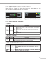
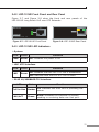
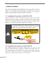
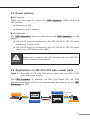
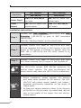
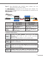
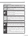
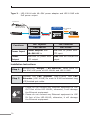
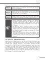
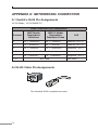
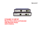
Long Reach PoE over Coaxial / UTP Extender Kit LRP-101C-KIT and LRP-101U-KIT User’s Manual Trademarks Copyright © PLANET Technology Corp. 2015. Contents are subject to revision without prior notice. PLANET is a registered trademark of PLANET Technology Corp. All other trademarks belong to their respective owners. Disclaimer PLANET Technology does not warrant that the hardware will work properly in all environments and applications, and makes no warranty and representation, either implied or expressed, with respect to the quality, performance, merchantability, or fitness for a particular purpose. PLANET has made every effort to ensure that this User’s Manual is accurate; PLANET disclaims liability for any inaccuracies or omissions that may have occurred. Information in this User’s Manual is subject to change without notice and does not represent a commitment on the part of PLANET. PLANET assumes no responsibility for any inaccuracies that may be contained in this User’s Manual. PLANET makes no commitment to update or keep current the information in this User’s Manual, and reserves the right to make improvements to this User’s Manual and/or to the products described in this User’s Manual, at any time without notice. If you find information in this manual that is incorrect, misleading, or incomplete, we would appreciate your comments and suggestions. FCC Warning This equipment has been tested and found to comply with the limits for a Class A digital device, pursuant to Part 15 of the FCC Rules. These limits are designed to provide reasonable protection against harmful interference when the equipment is operated in a commercial environment. This equipment generates, uses, and can radiate radio frequency energy and, if not installed and used in accordance with the Instruction manual, may cause harmful interference to radio communications. Operation of this equipment in a residential area is likely to cause harmful interference in which case the user will be required to correct the interference at his own expense. CE Mark Warning This is a Class A product. In a domestic environment, this product may cause radio interference, in which case the user may be required to take adequate measures. WEEE Warning To avoid the potential effects on the environment and human health as a result of the presence of hazardous substances in electrical and electronic equipment, end users of electrical and electronic equipment should understand the meaning of the crossed-out wheeled bin symbol. Do not dispose of WEEE as unsorted municipal waste and have to collect such WEEE separately. Revision PLANET Long Reach PoE over Coaxial / UTP Extender Kit User’s Manual MODELS: LRP-101C-KIT / LRP-101U-KIT REVISION: 1.0 (January 2015) Part No: EM-LRP-101x-KIT_v1.0 (2350-AN0100-000) TABLE OF CONTENTS 1.INTRODUCTION......................................................................... 6 1.1 Package Contents................................................................ 6 1.2 Introduction of Long Reach Power over Ethernet.................... 8 1.3 Product Features.................................................................. 9 1.4 Product Specifications.........................................................10 1.4.1 LRP-101C-KIT Specifications.......................................10 1.4.2 LRP-101U-KIT Specifications.......................................13 2. HARDWARE DESCRIPTION.........................................................16 2.1LRP-101CH.........................................................................16 2.1.1 LRP-101CH Physical Dimensions..................................16 2.1.2 LRP-101CH Front Panel and Rear Panel.......................17 2.1.3 LRP-101CH LED Indicators.........................................17 2.2LRP-101CE.........................................................................18 2.2.1 LRP-101CE Physical Dimensions..................................18 2.2.2 LRP-101CE Front Panel and Rear Panel........................19 2.2.3 LRP-101CE LED Indicators..........................................19 2.3LRP-101UH........................................................................20 2.3.1 LRP-101UH Physical Dimensions.................................20 2.3.2 LRP-101UH Front Panel and Rear Panel.......................21 2.3.3 LRP-101UH LED Indicators.........................................21 2.4LRP-101UE.........................................................................22 2.4.1 LRP-101UE Physical Dimensions..................................22 2.4.2 LRP-101UE Front Panel and Rear Panel........................23 2.4.3 LRP-101UE LED Indicators..........................................23 3.INSTALLATION..........................................................................24 3.1 Installation Precautions of LRP-101C-KIT..............................24 3.2 Installation Precautions of LRP-101U-KIT..............................24 3.3 Power options:...................................................................25 3.4 Applications of LRP-101C-KIT with coaxial cable....................25 3.5 Applications of LRP-101U-KIT with UTP/Twisted-pair Cable.....28 3.6.Optional - DIN-Rail Mounting...............................................31 4.TROUBLESHOOTING..................................................................33 APPENDIX A: NETWORKING CONNECTION........................................34 A.1 Switch’s RJ45 Pin Assignments.............................................34 A.2 RJ45 Cable Pin Assignments.................................................34 1.INTRODUCTION Thank you for purchasing PLANET Long Reach PoE over Coaxial / UTP Extender Kit, the LRP-101C-KIT and LRP-101U-KIT. The descriptions of the four models are as follows: LRP-101C-KIT LRP-101CH 1-Port 10/100TX PoE PD + 1-Port Coax Long Reach PoE Injector LRP-101CE 1-Port 10/100TX PoE PSE + 1-Port Coax Long Reach PoE Extender LRP-101U-KIT LRP-101UH 1-Port 10/100TX PoE PD + 1-Port UTP Long Reach PoE Injector LRP-101UE 1-Port 10/100TX PoE PSE + 1-Port UTP Long Reach PoE Extender “Long Reach PoE over Coaxial / UTP Extender Kit” mentioned in this Manual represents the above four models. 1.1 Package Contents Open the box of the Long Reach PoE over Coaxial / UTP Extender Kit and carefully unpack it. The box should contain the following items: For LRP-101C-KIT 1-Port 10/100TX PoE PD + 1-Port Coax Long Reach PoE Injector – LRP-101CH x 1 6 1-Port 10/100TX PoE PSE + 1-Port Coax Long Reach PoE Extender – LRP-101CE x 1 User’s Manual x 1 Warning Sticker x 1 For LRP-101U-KIT 1-Port 10/100TX PoE PD + 1-Port UTP Long Reach PoE Injector – LRP-101UH x 1 User’s Manual x 1 1-Port 10/100TX PoE PSE + 1-Port UTP Long Reach PoE Extender – LRP-101UE x 1 Warning Sticker x 2 Warning Sticker x 1 7 Note If any of these are missing or damaged, please contact your dealer immediately; if possible, retain the carton including the original packing material, and use them again to repack the product in case there is a need to return it to us for repair. 1.2 Introduction of Long Reach Power over Ethernet PLANET LRP-101C-KIT and LRP-101U-KIT series PoE over Coaxial Extender and PoE over UTP Extender are designed to extend IP Ethernet transmission and inject power over an existing coaxial, UTP or twisted-pair cable or for distance up to 1000m (3280ft) to PoE IP camera, PoE wireless AP and any 802.3af/at complied powered device (PD). It is a perfect solution for sending IP video links and power to remotely-installed PoE IP cameras that are beyond the 100 meters distance limit of Ethernet. Power over Coaxial, UTP or Twisted-pair cable The Long Reach PoE solution allows Ethernet Data and PoE or PoE+ to be transmitted using coaxial, UTP or twisted-pair cable. Based on IEEE 802.3at Power over Ethernet Plus and up to 25 watts of power output, PLANET Long Reach PoE extender solution eliminates the need for additional remote site power while allowing a single PoE source, such as a PoE network switch, to provide power to both LRP Extenders and the camera at long range. This feature eliminates the need for local and remote site power supplies. PoE IP Cam PoE LRP-101CE Extender Control Center LRP-101CH Injector Data Power Coaxial Cable Up to 1000m 8 Stable Operating Performance under Difficult Environments PLANET Long Reach PoE Extender is the perfect solution for extended distance data and power transmission for warehouses, parking lots, campuses, casinos, and many more. They can operate stably under temperature range from -20 to 70 degrees C which enables the users to conveniently apply the device in almost any location of the network. 1.3 Product Features Power over Ethernet zz Eliminates Power cabling with PoE over Coaxial zz Supports Power over Ethernet PSE, PoE Injector zz Power and Ethernet data transmission over coaxial up to 1km zz Power and Ethernet data transmission over UTP up to 500m zz Complies with IEEE 802.3af / IEEE 802.3at Power over Ethernet PD on RJ45 port zz Supports Long Reach PoE power up to 30.8 watts (Vary on power source and cable distance) zz Supports PoE Power up to 25 watts (Vary on power source and cable distance) zz Auto detect remote powered device (PD) zz Plug and Play, no PC required Industrial Case / Installation zz Supports extensive LED indicators for network diagnostics zz Metal case protection zz Compact size, DIN-rail and wall-mount design zz Supports 2000V DC EFT surge protection for power line zz Supports 2000V DC Ethernet ESD protection zz -20 to 70 degrees C operating temperature 9 1.4 Product Specifications 1.4.1 LRP-101C-KIT Specifications Model LRP-101CH LRP-101CE Functions Long Reach PoE Injector Long Reach PoE Extender Hardware Specifications Copper Power over Ethernet Standard Ethernet Interface Long Reach PoE Interface 10 10/100BASE-TX RJ45 Auto-negotiation/ Auto-MDI/MDI-X IEEE 802.3at/af PoE PD (Powered Device) IEEE 802.3at/af PoE PSE (Power Source Equipment) PoE Input Supports both Mid-Span and End-Span PSE Input Range: 48~56V DC ─ PoE Output ─ 48~56V DC, 600mA max. PoE Budget ─ Up to 25 watts PoE Mode ─ End-span, RJ45 Pin 1/2(+), 3/6(-) Data Rate 100/100Mbps Cabling Cat5e or above Maximum Distance 100 meters Maximum Frame sizes 1522bytes Connectivity 1 x BNC female connector Long Reach PoE over coaxial PSE (Power Source Equipment) 1 x BNC female Long Reach PoE over coaxial PD (Powered Device) Long Reach PoE Interface Power Input ─ 37~56V DC Power Output 41~56V DC ─ Power Pin Assignment BNC center pole : DC+ BNC shield : DC - BNC center pole : DC+ BNC shield : DC - Cabling Coaxial cable: 75 ohm RG-6/U cable, less than 12Ω/1000 ft RG-59/U cable, less than 30Ω/1000 ft. Maximum Distance Max. 200m with PoE+ output (656ft.) Max. 600m with PoE output (1968ft.) Max. 1200m without PoE output (3,937ft.) Long Reach Ethernet Standard IEEE 1901 Modulation Type Wavelet-OFDM Security 128-bit AES encryption Frequency Band 2 ~ 28 MHz Encryption AES 128-bit Performance** Distance Data Rate* (Upload / Download) 200m LRP-101CE 802.3af/at PoE Output Capability** LRP-101CH W/56V DC IN LRP-101CH W/30W PoE+ IN 93 / 93 Mbps 29W 16W 400m 93 / 93 Mbps 22W 14W 600m 87 / 91 Mbps 13W 10W 800m 75 / 83 Mbps 10W 8W 1000m 55 / 73 Mbps 8W 7W 11 LRP-101CE - 1-Port LRP Extender With power over coaxial input LRP-101CH – 1-Port LRP Injector LRP-822CS – 8-Port LRP over Coax Switch LRP-1622CS – 16-Port LRP over Coax Switch LED Indicators 4 x LEDs PWR LRP LNK PoE IN LNK/ACT 4 x LEDs PWR LRP LNK PoE-in-use LNK/ACT ESD Protection 2KV DC EFT Protection 2KV Enclosure Metal case Installation Wall mount or DIN rail with optional kit Dimensions (W x D x H) 94 x 70 x 26 mm Weight 200g Power Requirements BNC Power over Coaxial RJ45 PoE Input: Input: 44~56V DC 802.3at/af 48~56V DC DC Input: 48~56V DC Long Reach PoE Interface LRP Compatibility ─ 375g Standards Conformance Standards Compliance IEEE IEEE IEEE IEEE 802.3 10BASE-T Ethernet 802.3u 100BASE-TX Fast Ethernet 802.3af Power over Ethernet (802.3at Type 1) 802.3at Power over Ethernet (802.3at Type 2) Regulation Compliance FCC Part 15 Class A, CE Environment Temperature 12 Operating: -20~70 degrees C Storage: -40~75 degrees C Operating: 5~95% (Non-condensing) Storage: 5~95% (Non-condensing) Humidity *1.Upload: LRP-101CE to LRP-101CH. Download: LRP-101CH to LRP101CE. 2.As there are various resistance values in the category of RG-59/U or RG-6/U cable, the actual data rate will vary on the quality of the copper wire and environment factors. **Depending on what the DC/PoE Power Input and the length of coaxial cable are. 1.4.2 LRP-101U-KIT Specifications Model LRP-101UH LRP-101UE Hardware Specifications Copper Power over Ethernet Standard Ethernet Interface 10/100BASE-TX RJ45 Auto-negotiation/ Auto-MDI/MDI-X IEEE 802.3at/af PoE PD (Powered Device) IEEE 802.3at/af PoE PSE (Power Source Equipment) PoE Input Supports both Mid-Span and End-Span PSE Input Range: 48~56V DC PoE Output ─ 48~56V DC, 600mA max. PoE Budget ─ Up to 25 watts PoE Mode ─ End-span, RJ45 Pin 1/2(+), 3/6(-) Data Rate 100/100Mbps Cabling Cat5e or above Maximum Distance 100m Maximum Frame sizes 1522bytes 13 Long Reach PoE Interface Connectivity 1 x RJ45 connector Long Reach PoE over UTP PSE (Power Source Equipment) 1 x RJ45 connector Long Reach PoE over UTP PD (Powered Device) Power Input ─ 37~56V DC Power Output 41~56V DC Power Pin assignment RJ45 PIN 1,3,5,7: VCC+ RJ45 PIN 1,3,5,7: VCC+ RJ45 PIN 2,4,6,8: VCC- RJ45 PIN 2,4,6,8: VCC- Cabling UTP cable: Maximum distance Max. 100m with PoE+ output (328 ft.) Max. 400m with PoE output (1,312 ft.) Max. 500m without PoE output (1,640 ft.) Long Reach Ethernet Standard IEEE 1901 Modulation Type Wavelet-OFDM Security 128-bit AES encryption Frequency Band 2 ~ 28 MHz Encryption AES 128-bit Performance** 14 Distance Data Rate* (Upload / Download) 100m LRP-101UE 802.3af/at PoE Output Capability** LRP-101UH W/56V DC IN LRP-101UH W/30W PoE+ IN 94 / 94 Mbps 30W 19W 200m 82 / 82 Mbps 30W 18W 300m 63 / 67 Mbps 30W 17W 400m 44 / 48 Mbps 22W 14W 500m 30 / 30 Mbps 18W 12W LED Indicators 4 x LEDs PWR LRP LNK PoE IN LNK/ACT 4 x LEDs PWR LRP LNK PoE-in-use LNK/ACT ESD Protection 2KV DC EFT Protection 2KV Enclosure Metal case Installation Wall mount or DIN rail with optional kit Dimensions (W x D x H) 94 x 70 x 26 mm Weight 193g Power Requirements Power over RJ45 Input: RJ45 PoE Input: 44~56V DC 802.3at/af 48~56V DC DC Input: 48~56V DC ─ 190g Standards Conformance Standards Compliance IEEE IEEE IEEE IEEE 802.3 10BASE-T Ethernet 802.3u 100BASE-TX Fast Ethernet 802.3af Power over Ethernet (802.3at Type 1) 802.3at Power over Ethernet (802.3at Type 2) Regulation Compliance FCC Part 15 Class A, CE Environment Temperature Operating: -20~70 degrees C Storage: -40~75 degrees C Humidity Operating: 5~95% (non-condensing) Storage: 5~95% (non-condensing) *1.Upload: LRP-101UE to LRP-101UH. Download: LRP-101UH to LRP101UE. 2.As there are various resistance values in the category 5/5e cable, the actual data rate will vary on the quality of the copper wire and environment factors. ** Depending on what the DC/PoE Power Input and the length of UTP cable are. 15 2.HARDWARE DESCRIPTION 2.1LRP-101CH 2.1.1 LRP-101CH Physical Dimensions LRP-101CH dimensions (W x D x H): 94 x 70.3 x 26.2 mm Rear Panel PoE IN 48~56V DC IN LNK/ACT 10/100BASE-TX Top Panel Long Reach Power over Ethernet Bottom LRP-101CH LRP OUT Injector LNK CAUTION PWR Long Reach PoE Injector - Coax Front Panel 16 The LRP interface is allowed to connect to LRP Extender only. 2.1.2 LRP-101CH Front Panel and Rear Panel Figure 2-1 and Figure 2-2 show the front and rear panels of the LRP-101CH Long Reach PoE over Coaxial Injector. LRP-101CH LRP OUT Injector 48~56V DC IN PoE IN LNK/ACT LNK CAUTION PWR Long Reach PoE Injector - Coax The LRP interface is allowed to connect to LRP Extender only. Figure 2-1: LRP-101CH Front Panel 10/100BASE-TX Figure 2-2: LRP-101CH Rear Panel 2.1.3 LRP-101CH LED Indicators System LED PWR Color Green Function Lit Power ON: PoE+ / PoE power input from RJ45 PoE PD port Power ON: 48~56V DC power input from DC jack Off Power Off LRP Coaxial Interface LED LNK Color Green Function Lit: indicates that the coaxial link is established. Off: indicates that the coaxial link is down. RJ45 10/100BASE-TX Interface LED Color Function PoE IN Amber Lit: indicates the RJ45 port is receiving the PoE Power. LNK/ ACT Green Blink: indicates the extender is actively sending or receiving data over that port. 17 2.2LRP-101CE 2.2.1 LRP-101CE Physical Dimensions LRP-101CE dimensions (W x D x H): 94 x 70.3 x 26.2 mm Rear Panel PoE In-use LNK/ACT PoE OUT 10/100BASE-TX Top Panel Long Reach Power over Ethernet Bottom LRP-101CE LRP IN Extender LNK PWR Long Reach PoE Extender - Coax Front Panel 18 2.2.2 LRP-101CE Front Panel and Rear Panel Figure 2-3 and Figure 2-4 show the front and rear panels of the LRP-101CE Long Reach PoE over Coaxial Extender. LRP-101CE LRP IN PoE In-use Extender LNK/ACT LNK PoE OUT 10/100BASE-TX PWR Long Reach PoE Extender - Coax Figure 2-3: LRP-101CE Front Panel Figure 2-4: LRP-101CE Rear Panel 2.2.3 LRP-101CE LED Indicators System LED PWR Color Function Green Lit: indicates the power is on. LRP Coaxial Interface LED LNK Color Green Function Lit: indicates that the coaxial link is established. Off: indicates that the coaxial link is down. RJ45 10/100BASE-TX Interface LED Color Function PoE-in-Use Lit: indicates the RJ45 Port is providing PoE Amber power. LNK/ACT Green Blink: indicates the extender is actively sending or receiving data over that port. 19 2.3LRP-101UH 2.3.1 LRP-101UH Physical Dimensions LRP-101UH dimensions (W x D x H): 94 x 70.3 x 26.2 mm Rear Panel PoE IN 48~56V DC IN LNK/ACT 10/100BASE-TX Top Panel Long Reach Power over Ethernet Bottom LRP-101UH LRP OUT LNK CAUTION Injector The LRP interface is allowed to connect to LRP Extender only. PWR Long Reach PoE Injector - UTP Front Panel 20 2.3.2 LRP-101UH Front Panel and Rear Panel Figure 2-5 and Figure 2-6 show the front and rear panels of the LRP-101UH Long Reach PoE over UTP Injector. LRP-101UH LRP OUT 48~56V DC IN PoE IN LNK/ACT LNK CAUTION The LRP interface is allowed to connect to LRP Extender only. Injector 10/100BASE-TX PWR Long Reach PoE Injector - UTP Figure 2-5: LRP-101UH Front Panel Figure 2-6: LRP-101UH Rear Panel 2.3.3 LRP-101UH LED Indicators System LED PWR Color Green Function Lit Power ON: PoE+ / PoE power input from RJ45 PoE PD port Power ON: 48~56V DC power input from DC jack Off Power Off LRP UTP Interface LED LNK Color Green Function Lit: indicates that the UTP link is established. Off: indicates that the UTP link is down. RJ45 10/100BASE-TX Interface LED Color Function PoE IN Lit: indicates the RJ45 port is receiving the PoE Amber Power. LNK/ ACT Green Blink: indicates the extender is actively sending or receiving data over that port. 21 2.4LRP-101UE 2.4.1 LRP-101UE Physical Dimensions LRP-101UE dimensions (W x D x H): 94 x 70.3 x 26.2 mm Rear Panel PoE In-use LNK/ACT PoE OUT 10/100BASE-TX Top Panel Long Reach Power over Ethernet Bottom LRP-101UE LRP IN LNK Extender PWR Long Reach PoE Extender - UTP Front Panel 22 2.4.2 LRP-101UE Front Panel and Rear Panel Figure 2-7 and Figure 2-8 show the front and rear panels of the LRP-101UE Long Reach PoE over UTP Extender. LRP-101UE PoE In-use LRP IN LNK/ACT LNK PoE OUT Extender 10/100BASE-TX PWR Long Reach PoE Extender - UTP Figure 2-7: LRP-101UE Front Panel Figure 2-8: LRP-101UE Rear Panel 2.4.3 LRP-101UE LED Indicators System LED PWR Color Function Green Lit: indicates the power is on. LRP UTP Interface LED LNK Color Green Function Lit: indicates that the LRP UTP link is established. Off: indicates that the LRP UTP link is down. RJ45 10/100BASE-TX Interface LED Color Function PoE-in-Use Lit: indicates the RJ45 Port is providing PoE Amber power. LNK/ACT Green Blink: indicates the extender is actively sending or receiving data over that port. 23 3.INSTALLATION This section describes the functionalities of the Long Reach PoE over Coaxial / UTP Extender Kit’s components and guides you to how to install it on the desktop. Basic knowledge of networking is expected. Please read this chapter completely before continuing. 3.1 Installation Precautions of LRP-101C-KIT As the LRP-101CH is power over coaxial injector, it only can work with PLANET power over coaxial extender, the LRP-101CE. Please confirm that other non-PoE equipment is not connected with the coaxial cable. When you connect the coaxial cable with coax-LAN converter, CCTV camera, etc, it might cause other equipment to damage. The package contains one Warning Sticker, which should be stuck on the coaxial cable connector before using PLANET Long Reach PoE over Coaxial Extender Kit. ase e Wa rem in rn Ple co in de nt d th ca ains g: Th re at the ful elec is si the de befo tric de vice re po of ca . plug wer conn ble ging . Pl ec ea co into se tor n be Caution b Do Not Touch the Center Pin 3.2 Installation Precautions of LRP-101U-KIT The package contains one Warning Sticker and it is stuck on the PoE IN / LRP OUT RJ45 connector of PLANET Long Reach PoE over UTP Extender Kit. As the LRP-101UH is power over UTP, it only can work with PLANET LRP-101UE. If connected with standard Ethernet equipment, it might cause damage to the equipment. 24 3.3 Power options: LRP Injector There are two ways to power the LRP Injector (LRP-101CH and LRP-101UH): Powered via PoE Powered via DC adapter LRP Extender The LRP Extender must be powered by the LRP Injector or LRP Switch LRP-101CE must be powered by the LRP-101CH or LRP CS-series switch over coaxial cable LRP-101UE must be powered by the LRP-101UH or LRP US-series switch over UTP/Twisted-pair cable Caution Please don’t connect the LRP Extender to any PoE PSE (Power Sourcing Equipment). 3.4 Applications of LRP-101C-KIT with coaxial cable Type 1 –One LRP-101CH with PoE power input and one LRP-101CE with PoE power output The LRP Injector is powered via IEEE 802.3at/af PoE. An IEEE 802.3at/af compliant PoE PD will automatically be powered by the LRP Extender via UTP. LRP-101CE Long Reach PoE Extender PoE 802.3af/802.3at PoE Long Reach Power over Ethernet PoE Long Reach Power over Ethernet 802.3af / 802.3at PoE Switch CAT5e/6 PoE CAT5e/6 LRP-101CH Long Reach PoE Injector Power over Coaxial PoE IP Camera 25 Functions LRP Injector LRP Extender LRP-101CH LRP-101CE Power Input RJ45 with 802.3at/af PoE input BNC with DC power over coaxial input Power Output BNC with DC power over coaxial output RJ45 with 802.3at/af PoE output Installation Instructions Step 1 Connect the LRP Injector (LRP-101CH) and LRP Extender (LRP-101CE) to ends of BNC terminated coaxial cable. Stick the “Warning Sticker” on the coaxial cable. Step 2 Connect Cat5/6 UTP cable to LRP-101CH and IEEE 802.3at compliant PoE Switch or PoE Injector. If the PoE switch or PoE injector is powered on already, then the PWR LED of LRP-101CH and LRP-101CE should lit up immediately. Step 3 Connect Cat5/6 UTP cable to LRP-101CE and IEEE 802.3at/af complied PoE IP camera or PoE Wireless AP. Warning Note 26 The LRP-101CH accepts IEEE 802.3at equipment for optimal power injection. The other non-standard PoE power devices may cause the LRP-101CH to malfunction. 1. Before installation, please consider the distance and watts value demand for PD devices. The LRP101C-KIT PoE powers output capacity and upload / download performance depending on the length of coaxial cable. 2.As there are various resistance values in the category of RG-59/U or RG-6/U cable, the actual data rate will vary on the quality of the copper wire and environmental factors. Type 2 – One LRP-101CH with 48~56V power adapter and one LRP-101CE with PoE power output The LRP Injector is powered via the external power adapter. The IEEE 802.3at/af compliant PoE PD will automatically be powered by the LRP Extender via UTP. 110-240V AC AC-to-DC Adapter 60W/48~56V DC IN LRP-101CE Long Reach PoE Extender 802.3af/802.3at PoE Long Reach Power over Ethernet PoE CAT5e/6 Long Reach Power over Ethernet Ethernet Switch LRP-101CH Power over Coaxial Long Reach PoE Injector Functions CAT5e/6 PoE IP Camera LRP Injector LRP Extender LRP-101CH LRP-101CE Power Input Power adapter with 48~56V DC in BNC with DC power over coaxial input Power Output BNC with DC power over coaxial output RJ45 with 802.3at/af PoE output Installation Instructions Step 1 Connect the LRP Injector (LRP-101CH) and LRP Extender (LRP-101CE) to ends of BNC terminated coaxial cable. Stick the “Warning Sticker” on the coaxial cable. Step 2 Connect Cat5/6 UTP cable to LRP-101CH and non-PoE switch or workstation. Step 3 Connect 48~56V DC power adapter to LRP-101CH power socket, then the PWR LED of LRP-101CH and LRP-101CE should lit up immediately. Step 4 Connect Cat5/6 UTP cable to LRP-101CE and IEEE 802.3at/af complied PoE IP camera or PoE Wireless AP. 27 Note 1. Before installation, please consider the distance and watts value demand for PD devices. The LRP101C-KIT PoE powers output capacity and upload / download performance depending on the length of coaxial cable. 2.As there are various resistance values in the category of RG-59/U or RG-6/U cable, the actual data rate will vary on the quality of the copper wire and environment al factors. 3.PoE output capacity is based on different DC Power Input / PoE Input. 4.The LRP-101CH has two power input options; only one mode is available at one time. PoE power input cannot be used if power input of DC 52V or 56V is selected. 3.5Applications of LRP-101U-KIT with UTP/Twisted-pair Cable Type 1 –LRP-101UH with PoE power input and LRP-101UE with PoE power output 802.3af / 802.3at PoE Switch LRP-101UE Long Reach PoE Extender PoE 802.3af/802.3at PoE Long Reach Power over Ethernet PoE Long Reach Power over Ethernet CAT5e/6 LRP-101UH Long Reach PoE Injector Functions PoE CAT5e/6 Power over UTP PoE IP Camera LRP Injector LRP Extender LRP-101UH LRP-101UE Power Input RJ45 with 802.3at/af PoE input UTP with DC power over UTP input Power Output UTP with DC power over UTP output RJ45 with 802.3at/af PoE output 28 Installation Instructions Step 1 Remove the “Danger – No Ethernet” labels stuck on the RJ45 LRP port of LRP-101UH and LRP-101UE. Step 2 Connect the LRP Injector (LRP-101UH) and LRP Extender (LRP-101UE) to ends of RJ45 terminated long UTP/twisted-pair cable. Warning 1.Please do not connect any Ethernet equipment to LRP OUT Port of the LRP-101UH; otherwise, it will damage the Ethernet equipment. 2.Please do not connect any Ethernet equipment to LRP IN Port of the LRP-101UE; otherwise, it will damage the Ethernet equipment. Step 3 Connect Cat5/6 UTP cable to LRP-101UH and IEEE 802.3at compliant PoE Switch or PoE Injector. If the PoE switch or PoE injector is powered on already, then the PWR LED of LRP-101UH and LRP-101UE should lit up accordingly. Step 4 Connect Cat5/6 UTP cable to LRP-101UE and IEEE 802.3at/af complied PoE IP camera or PoE Wireless AP. Warning Note The LRP-101UH accepts IEEE 802.3at equipment for optimal power injection. The other non-standard PoE Power devices may cause the LRP-101UH to malfunction. 1. Before installation, please consider the distance and watts value demand for PD devices. The LRP101U-KIT PoE powers output capacity and upload / download performance depending on the length of UTP cable. 2.As there are various resistance values in the category 5/5e cable, the actual data rate will vary on the quality of the copper wire and environmental factors. 29 Type 2 –LRP-101UH with 48~56V power adapter and LRP-101UE with PoE power output 110-240V AC AC-to-DC Adapter 60W/48~56V DC IN LRP-101UE Long Reach PoE Extender 802.3af/802.3at PoE Long Reach Power over Ethernet PoE CAT5e/6 Long Reach Power over Ethernet Ethernet Switch LRP-101UH Power over UTP Long Reach PoE Injector Functions CAT5e/6 PoE IP Camera LRP Injector LRP Extender LRP-101UH LRP-101UE Power Input Power adapter with 48~56V DC in UTP with DC power over UTP input Power Output UTP with DC power over UTP output RJ45 with 802.3at/af PoE output Installation Instructions Step 1 Remove the “Danger – No Ethernet” labels stuck on the RJ45 LRP ports of LRP-101UH and LRP-101UE. Step 2 Connect the LRP Injector (LRP-101UH) and LRP Extender (LRP-101UE) to ends of RJ45 terminated long UTP/twisted-pair cable. Warning 30 1.Please do not connect any Ethernet equipment to LRP OUT Port of the LRP-101UH; otherwise, it will damage the Ethernet equipment. 2.Please do not connect any Ethernet equipment to LRP IN Port of the LRP-101UE; otherwise, it will damage the Ethernet equipment. Step 3 Connect Cat5/6 UTP cable to LRP-101UH and non-PoE switch or workstation. Step 4 Connect 48~56V DC power adapter to LRP-101UH power socket, and then the PWR LED of LRP-101UH and LRP101UE should lit up immediately. Step 5 Connect Cat5/6 UTP cable to LRP-101UE and IEEE 802.3at/af complied PoE IP camera or PoE Wireless AP. Note 1. Before installation, please consider the distance and watts value demand for PD devices. The LRP101U-KIT PoE powers output capacity and upload / download performance depending on the length of UTP cable. 2.As there are various resistance values in the category 5/5e cable, the actual data rate will vary on the quality of the copper wire and environmental factors. 3.PoE Output Capacity is based on different DC Power Input / PoE Input. 4.The LRP-101UH has two power input options; only one mode is available at one time. PoE power input cannot be used if power input of DC 52V or 56V is selected. 3.6.Optional - DIN-Rail Mounting There are two DIN-Rail holes on the left side of the Long Reach PoE over Coaxial / UTP Extender Kit that allow the device to be easily installed with DIN-Rail mounting. The PLANET optional DIN-Rail mounting Kit – RKE-DIN can be ordered separately. When you need to replace the wall mount application with DIN-Rail application on the Long Reach PoE over Coaxial / UTP Extender Kit, please refer to following figures to screw the DIN-Rail on the Long Reach PoE over Coaxial/UTP Extender Kit. To hang the Long Reach PoE over Coaxial / UTP Extender Kit, follow the steps below: 31 Step 1: Screw the DIN-Rail on the Long Reach PoE over Coaxial / UTP Extender Kit. Step 2: Lightly slide the DIN-Rail into the track. 1 2 Step 3: Check whether the DIN-Rail is tightly on the track. Caution 32 You must use the screws supplied with the mounting brackets. Damage caused to the parts by using incorrect screws would invalidate your warranty. 4.TROUBLESHOOTING This chapter contains information to help you solve issues. If the Long Reach PoE over Coaxial / UTP Extender Kit is not functioning properly, make sure the Long Reach PoE over Coaxial / UTP Extender Kit is set up according to instructions in this manual. What is the maximum distance supported by LRP-101C-KIT and LRP-101U-KIT? Solution: 1.The LRP-101C-KIT supports a maximum distance of 1km. 2.The LRP-101U-KIT supports a maximum distance of 500m. May I know which power source that can be accepted by LRP101C-KIT and LRP-101U-KIT? Solution: 1.DC 56V power adapter. 2.DC 48V power adapter. 3.IEEE 802.3at High Power over Ethernet Switch. 4.IEEE 802.3af Power over Ethernet Switch. The LRP-101C-KIT and LRP-101U-KIT Performance is bad. Solution: The actual data rate will vary on the quality of the coaxial / UTP cable and environment factors. 33 APPENDIX A: NETWORKING CONNECTION A.1 Switch’s RJ45 Pin Assignments 10/100Mbps, 10/100BASE-TX RJ45 Connector pin assignment Contact MDI Media Dependent Interface MDI-X Media Dependent Interface-Cross PoE 1 Tx + (transmit) Rx + (receive) Positive (VCC+) 2 Tx - (transmit) Rx - (receive) Positive (VCC+) 3 Rx + (receive) Tx + (transmit) Negative (VCC-) 4, 5 6 7, 8 Not used Rx - (receive) Tx - (transmit) Not used A.2 RJ45 Cable Pin Assignments The standard RJ45 receptacle/connector 34 Not used Negative (VCC-) Not used There are 8 wires on a standard UTP/STP cable and each wire is colorcoded. The following shows the pin allocation and color of straight cable and crossover cable connection: Straight Cable 1 2 3 4 5 6 7 8 1 2 3 4 5 6 7 8 Crossover Cable 1 2 3 4 5 6 7 8 1 2 3 4 5 6 7 8 SIDE 1 SIDE 2 SIDE 1 SIDE 2 SIDE 1 1 = White/Orange 2 = Orange 3 = White/Green 4 = Blue 5 = White/Blue 6 = Green 7 = White/Brown 8 = Brown SIDE 2 1 = White/Orange 2 = Orange 3 = White/Green 4 = Blue 5 = White/Blue 6 = Green 7 = White/Brown 8 = Brown SIDE 1 SIDE 2 1 = White/Orange 2 = Orange 3 = White/Green 4 = Blue 5 = White/Blue 6 = Green 7 = White/Brown 8 = Brown 1 = White/Green 2 = Green 3 = White/Orange 4 = Blue 5 = White/Blue 6 = Orange 7 = White/Brown 8 = Brown Figure A-1: Straight-through and Crossover Cable Please make sure your connected cables are with the same pin assignment and color as the above picture before deploying the cables into your network. 35 EC Declaration of Conformity For the following equipment: *Type of Product: 1-Port 10/100TX PoE PD + 1-Port Coax Long Reach PoE Injector 1-Port 10/100TX PoE PSE + 1-Port Coax Long Reach PoE Extender 1-Port 10/100TX PoE PD + 1-Port UTP Long Reach PoE Injector 1-Port 10/100TX PoE PSE + 1-Port UTP Long Reach PoE Extender *Model Number: LRP-101CH, LRP-101CE LRP-101UH, LRP-101UE * Produced by: Manufacturer’s Name : Manufacturer’s Address: Planet Technology Corp. 10F., No.96, Minquan Rd., Xindian Dist. New Taipei City 231, Taiwan (R.O.C.). We hereby confirmed that the products mentioned comply with the requirements set out in the Council Directive on the Approximation of the Laws of the Member States relating to Electromagnetic Compatibility (2004/108/EC). For the evaluation regarding the EMC, the following standards were applied: EN55022 EN 61000-3-2 EN 61000-3-3 EN55024 IEC 61000-4-2 IEC 61000-4-3 IEC 61000-4-4 IEC 61000-4-5 IEC 61000-4-6 IEC 61000-4-8 IEC 61000-4-11 (2010) (2006 + A1:2009 + A2:2009) (2008) (2010) (2008) (2006 + A1: 2007 + A2: 2010) (2012) (2005) (2008) (2009) (2004) Responsible for marking this declaration if the: Manufacturer Authorized representative established within the EU Authorized representative established within the EU (if applicable): Company Name: Planet Technology Corp. Company Address: 10F., No.96, Minquan Rd., Xindian Dist., New Taipei City 231, Taiwan (R.O.C.) Person responsible for making this declaration Name, Surname Kent Kang Position / Title : Product Manager Taiwan Place 31st March, 2015 Date Legal Signature PLANET TECHNOLOGY CORPORATION e-mail: [email protected] http://www.planet.com.tw 10F., No.96, Minquan Rd., Xindian Dist., New Taipei City, Taiwan, R.O.C. Tel:886-2-2219-9518 Fax:886-2-2219-9528