1
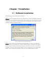
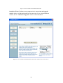
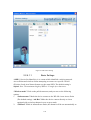
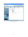
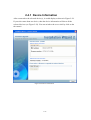
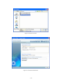
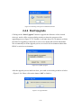
Installation Wizard 2
User’s Manual
Contents
Chapter 1
Installation.......................................................................................... 1-1
1.1 Software Installation ................................................................................ 1-1
Chapter 2
Using Installation Wizard 2 ............................................................... 2-4
2.1 User Interface........................................................................................... 2-4
2.1.1 Action buttons................................................................................. 2-7
2.1.2 Function buttons.............................................................................. 2-8
2.2 Manual Setup ......................................................................................... 2-10
2.2.1 System Setting ...............................................................................2-11
2.2.2 Network Setting ............................................................................ 2-13
2.2.3 Ports Setting .................................................................................. 2-16
2.2.4 DDNS Setting ............................................................................... 2-17
2.2.5 Mobile Access............................................................................... 2-20
2.2.6 Wireless Setting ............................................................................ 2-20
2.2.7 Apply to selected device ............................................................... 2-26
2.3 Access Information ................................................................................ 2-28
2.4 Upgrade.................................................................................................. 2-32
2.4.1 Device Information ....................................................................... 2-33
2.4.2 Firmware Information................................................................... 2-34
2.4.3 Select Firmware ............................................................................ 2-34
2.4.4 Start Upgrade ................................................................................ 2-36
Chapter 1 Installation
1.1 Software Installation
The following are steps for the software installation.
STEP 1: Put the Installation disk into the CD-ROM drive, and the installation should start
automatically. If the installation does not start, click on “Start” on the lower left corner of your
screen, open “My Computer” and double click on the CD-ROM icon. The Installation Wizard 2
Installation Window will appear as Figure 1-1.
Figure 1-1 Installation Wizard 2 Installation Window
STEP 2: Please read the license agreement first, and then click on “I Agree” to continue the
installation process. The install process will go on and then Figure 1-2 will appear. This page is
for you to select the additional component you want to install. The component “Create shortcut
on desktop” will create a shortcut on the desktop. It is more convenient for you to launch Install
Wizard 2. After selecting the components, please click on the “Next” Button to continue.
1-1
Figure 1-2 Select components to install for the Installation Wizard 2
STEP 3: Select the installation directory for this application software and click on “Install”
button. You can also change the installation directory by clicking on “Browse…” button. After
the proper directory chose, please click on the “Install” button to continue.
Figure 1-3 Destination Location for Installation
STEP 4: After clicking “Install” button, the install system will install the Installation Wizard 2 to
your computer, and a progress bar will display on the dialog. After completed the installation,
please click on the “Close” button (Figure 1-4).
1-2
Figure 1-4 Completed
1-3
Chapter 2
Using Installation
Wizard 2
2.1 User Interface
Figure 2-1 Analyze network environment
The Installation Wizard 2 had distributed the network type into 6 groups, such as
Private fixed IP, Private DHCP, PPPoE, Public fixed IP, Public DHCP and No
2-4
Connection to Internet. Once you run the Installation Wizard 2, it will do some
analysis toward your network environment like Figure 2-1. Then, the dialog window
will display your network type after finished the detection. For example, if there is a
DHCP server on your LAN, using DHCP function to set up the device may easier
than the other option.
Please click on the “Next” button to continue the program. After a short searching
time, you will see the user interface as shown in Figure 2-2. “Manual Setup” button,
a “Refresh Devices” button and an arrow button on the left panel of your user
interface. When you click on the arrow button, you will see more advanced
functional buttons: “Access Information”, “Firmware Upgrade”, “Restore
Default” and “About IW2”(Figure 2-3). You can select your device by
double-clicking it in the device list. The left four buttons (“Manual Setup”,
“Access Information”, “Firmware Upgrade”, and “Restore Default”) won’t be
enabled until you select at least one device.
2-5
Figure 2-2 User interface of Installation Wizard 2
Installation Wizard 2 allows you to setup one device at one time and upgrade
multiple devices (of the same model) at the same time. If you selected different
models, then the “Firmware Upgrade” button would be disabled.
Figure 2-3 User interface of Installation Wizard 2 after clicking on the arrow button
2-6
2.1.1 Action buttons
Figure 2-4 Refresh devices
Clicking on the “Refresh Devices” button will refresh the device list (Figure 2-4)
and search all devices on the LAN again. Refreshing the device list will take several
seconds.
If you want to link to your device, double-clicking it on your device list will lead
you to the browser for operating your device.
2-7
2.1.2 Function buttons
Figure 2-5 Function buttons
Click on this button to modify the setting of the selected devices. For more detail,
please refer to 2.2 Manual Setup.
Click on this button to upgrade the firmware of the selected devices. For more detail,
please refer to 2.4 Upgrade
2-8
Click on this button to get the access information, it will show you the IP Address
information, DDNS information, UPnP Port Forwarding information, and PPPoE
connecting information. For more detail, please refer to 2.5 Access Information.
Click on this button to restore the selected device to factory default.
Click on this button to get version information of the Installation Wizard 2.
2-9
2.2 Manual Setup
When you select one device in the selection list, the “Manual Setup” button
will be enabled. Click on it to modify the settings of the selected device. After
clicked on the “Manual Setup” button, Installation Wizard 2 would try to connect
to the selected device.
If the authentication is failed, there would be a pop-up dialog window (see Figure
2-6) to ask for correct password. If you failed three times, the Installation Wizard 2
would show you a warning dialog window (
Figure 2-7) and abort the connecting to the selected device.
Figure 2-6 Authentication Dialog Window
2-10
Figure 2-7 Authentication error
2.2.1 System Setting
After connected to the selected device, the Installation wizard 2 will switch to
system setting page as shown in Figure 2-8.
Figure 2-8 System setting page
Click on this button to cancel the setup progress.
Click on this button to keep the present setting and go to the next page.
2-11
2.2.1.1.1
Change Host Name
The “Hostname” is used for the homepage title of main page and is displayed as the
title in the video window of the main page. The maximum string length is 40
characters or 20 characters in double-byte-character-systems like Chinese or Japanese.
But for some models supported Unicode, the maximum string length depends on the
characters you input, and it may less than 20 characters.
2.2.1.1.2
Change root password
To change the administrator’s password, type the new password in both “Password”
and “Confirm Password” text boxes identically. What is typed will be displayed as
asterisks for security purposes. The maximum password depends on the server you
connected.
2.2.1.1.3
Adjust date and time
Figure 2-9 Date/Time setup
There are three ways to adjust system date and time (Figure 2-9):
1.
"Synchronize with computer time": The easiest way is to make device
synchronized with your computer time.
2.
“Set date and time manually”: Set the date and time manually by entering
new values. Notice the format in the related field while typing.
3.
“Synchronize to network time server automatically”: Make device
automatically synchronize with timeservers over the Internet every hour.
If you want to keep the current date and time, please choose “Keep current date
and time”.
2-12
2.2.2 Network Setting
The Installation Wizard 2 can help you to setup the network connection with LAN or
PPPoE. After you clicked on the “Next” button on the System page, the Installation
Wizard 2 would lead you to the PPPoE setting page(Figure 2-10). If you want to
connect your server to Internet via PPPoE, please click on “Yes” to start the PPPoE
setting process, or click on “No” to invoke the LAN setting.
Figure 2-10 Choosing the network type
2-13
2.2.2.1.1
PPPoE Setting
Figure 2-11 Network setting for PPPoE
If you click on “Yes” in the “Network Type” dialog window, you will be led to the
PPPoE setting page. In this page, you can input the “PPPoE username” and
“PPPoE password” provided by your ISP, and then the server will be set to PPPoE
mode rather than LAN mode when the setup is completed. If you don’t know the
account information, please contact your ISP. After inputting the account
information, please click on the “Next” button to continue your next step.
2-14
2.2.2.1.2
LAN Setting
If you click on “No” in the “Network Type” dialog window, you will be led to the
Network setting page. In this page, you can change the server’s IP address, subnet
mask, default gateway, primary DNS server, secondary DNS and DHCP server.
Please refer to Figure 2-12.
Figure 2-12 Network Setting for LAN
You could set up the network with DHCP or fixed IP:
1. DHCP: Check the "Get IP by DHCP Server automatically" will force the
device to renew its IP address whenever it reboots, and the related network
configuration is provided by the DHCP server.
2. Fixed IP: If you want the device to use a fixed IP, please uncheck the "Get IP by
DHCP Server automatically" checkbox and assign a valid IP address, subnet
mask, default gateway and DNS server for the device.
2-15
2.2.3 Ports Setting
If your device is located behind the router (such as private fixed IP, private DHCP)
and you want to access it through the LAN, your router must be configured first. The
ports setting page (Figure 2-13) will appear after you click on the “Next” button of
Network Setting page. The UPnP technology will configure your router
automatically, but if your router doesn’t support UPnP, you need to configure the
port numbers manually. The Installation Wizard 2 will detect whether your router
support UPnP or not. If your router support UPnP, Installation wizard 2 will choose
the “UPnP port forwarding” for you, otherwise it will choose the “Manual” mode
and you have to inspect those port numbers and make the port mapping on your
router manually.
Figure 2-13 UPnP Port Forwarding setting
2-16
2.2.4 DDNS Setting
Figure 2-14 DDNS Setting
The DDNS (Dynamic Domain Name Service) is a method of keeping a domain
name mapping to a dynamic public IP address. In many cable/DSL connections, a
dynamic public IP address is assigned for every connecting request. After you setup
your DDNS service, and then the device would automatically update your connect
information if the public IP address had been changed.
You have to enter the “Host name”, “E-Mail address”, “Key” and “Confirm key”
to initiate the DDNS. The “Host name” should be 1~64 character(s), and the
“E-Mail address” will receive some DDNS information, please input your e-mail
address carefully.
2-17
If you have a fixed public IP, or you don’t plan to access the camera on LAN, you
may unchecked the “Enable DDNS” to disable the DDNS function.
If you forgot your DDNS key (password), you could input the Hostname and E-mail
address first, and then click on the “Forget Key” button. The key will be sent to your
e-mail box by the DDNS provider automatically.
If the hostname haven’t been registered before, you should click on the “Register
DDNS” to register the hostname. If you didn’t register the DDNS (now and before),
it might not work properly.
The DDNS provider usually has a minimal time interval of each registration, for
Safe100.net, it is about 10 minutes.
If you want to use another DDNS rather than safe100.net, you can click on the
“Advanced Information” to change the DDNS provider. There are two service
providers in the advanced setting, one is saf100.net and another is Custom DDNS
server. If you choose the Custom DDNS server, you have to enter the Server address
and the DDNS domain name, and you may refer to Figure 2-15.
2-18
Figure 2-15 Advanced DDNS Setting
2-19
2.2.5 Mobile Access
After finished the DDNS setting and click on the Next button. If your device
supports mobile viewer and you want to access the device by mobile phone, you can
enable the “Mobile Access” (Figure 2-16) by clicking on the Yes button. The
Installation Wizard 2 will do some setting for mobile viewing toward the device:
1. Video: The video codec will be set to MPEG-4, and the resolution will be set to
176x144 pixels.
2. Audio: The audio codec will be set to AAC.
Figure 2-16 Mobile Access
2.2.6 Wireless Setting
Figure 2-17 Ask if you want to setup the wireless configuration
This above page(Figure 2-17) will show up only when you select the model with
wireless support. It allows you to configure the wireless setting. Please refer to Figure
2-18.
2-20
Figure 2-18 Wireless Setting
2.2.6.1.1
Basic Settings
“SSID” (Service Set Identifier), it is a name which identified a wireless network.
Access Points and wireless clients attempting to connect to a specific WLAN
(Wireless Local Area Network) must use the same SSID. The default setting is
default. Note: The maximum length of SSID is 32 single-byte characters.
“Wireless mode” Click on the pull-down menu, and you can see the following
options:
1.
“Infrastructure” Make the device connect to the WLAN via an Access Point
(The default setting). “Ad-Hoc” Make the device connect directly to a host
equipped with a wireless adapter in peer-to-peer mode.
2.
“Channel” While in infrastructure mode, the channel will be set automatically to
2-21
the same channel setting of the selected Access Point. While in Ad-Hoc mode,
the channel must be set to the same channel for each wireless adapter. The
default channel setting depends on the installed region.
2-22
2.2.6.1.2
Data Encryption
“Encrypt” You can choose the encryption type you want in the pull-down menu,
there are three items: None, WEP and WPA-PSK.
2.2.6.1.3
None
If your wireless environment doesn’t need encryption, please choose “None”.
2.2.6.1.4
WEP
If your encryption is WEP, please choose the “WEP” in the Encrypt pull-down
menu (Figure 2-19), and you have to enter the following information.
Figure 2-19 WEP Setting page
2-23
“Auth. Mode” Choose one of the following modes,
“Shared” – allows communication only with other devices on identical WEP
settings.
“Open” – communicates the key across the network.
“Key length”: The administrator can select the key length among 64 or128 bits. The
selection will depend on the selected device.
“Key format”: Hexadecimal or ASCII.
“HEX” digits consist of the numbers 0~9 and the letters A-F.
“ASCII” is a code for representing English letters as numbers from 0-127 except “,
<, > and space characters that are reserved.
“Key”: Enter a key in either hexadecimal or ASCII format. When selecting different
key length, acceptable input length is listed as following:
64 bits key length: 10 Hex digits or 5 characters.
128 bites key length: 26 Hex digits or 13 characters.
2.2.6.1.5
WPA-PSK
If your encryption type is WPA, please choose the “WPA-PSK”. And you have to
enter the pre-shared key and choose a proper encryption algorithm (TKIP, AES)
2-24
Figure 2-20 WPA-PSK Setting page
2-25
2.2.7 Apply to selected device
After configuring all the settings, the apply page will show up (Figure 2-21). Click
on “Apply” button to apply the changes to the selected device or click on “Back”
button to go back to the previous page and modify the setting again.
Figure 2-21 Apply page
When you click on the “Apply”, it will start to update your settings to server. When
it completed, it will show the access information of this server for you. Please refer
to 2.3 Access Information for the details.
2-26
Figure 2-22 Access Information
2-27
2.3 Access Information
The access information page shows you all the information about how to access the
server. There are three access types:
1.
Access from Home: If you access the server from home, you could use the
domain name (or IP address) and port (if the http port is not 80) to connect the
server.
2.
Access from Internet: If you access the server from Internet, or you want to
share the server with your family or friends, you should use this IP Address (or
domain name) and port. If the server is behind the router, it will check whether
the UPnP or port mapping is enabled. If the UPnP and port mapping is failed, it
will show a “Warning Icon” after the link. If the “Warning Icon” appears after
the link, the server won’t be able to access from Internet.
3.
Access from Quicktime: If your server supports the RTSP, A link will be
displayed for you to access from QuickTime or other devices supported RTSP
(such as 3GPP Mobile Phone). You can connect to the server via this link.
2-28
In the access information page, you can click on the “Advanced Information” to get
more information.
1.
Network type: The network type of server, it could be PPPoE, DHCP or Fixed
IP
2.
3.
4.
5.
UPnP status: The UPnP status, it could be Disabled, Success, Failed
DDNS status: The DDNS status, it could be Disabled, Success, Failed
PPPoE status: The PPPoE status, it could be Disabled, Success, Failed
Wireless status: If your device supports wireless, the status will be Connected
or Disconnected. If the device doesn’t support wireless, it will display an
unsupported message.
Some server don’t have certain fields in the advanced information, it may show
“Unknown” in some status fields.
2-29
There are “Add to my favorite” and “Export to desktop” buttons on this page:
1.
“Add to my favorite” is for you to add the Access Information to your
bookmark of browser. It helps you to access the server easier.
Figure 2-23 Add to my favorite message
Figure 2-24 the bookmark of your browser after added the link to your favorite
2.
“Export to desktop” will generate an html file on your desktop, and you can
open this file by your browser and see the access information of this server.
Figure 2-25 Generated html file message
2-30
Figure 2-26 html file generated in browser
2-31
2.4 Upgrade
When you select one device or multiple devices (of the same model), the
“Firmware Upgrade” button will be enabled. Click on it to upgrade the firmware
of the selected device(s) (Figure 2-27). After click on the “Firmware Upgrade”
button, Installation Wizard 2 will try to connect the selected device(s) and lead you
to the firmware upgrade page.
Figure 2-27 Click on the “Firmware Upgrade”
2-32
2.4.1 Device Information
After connected to the selected device(s), it would display as shown in Figure 2-28.
If you select more than one device, then the device information will show all the
selected devices (see Figure 2-29). You can switch to the server info by click on the
tab control.
Figure 2-28 Device information
2-33
Figure 2-29 Multiple devices information
2.4.2 Firmware Information
The selected firmware information will show the information about the file that you
selected.
z
Firmware version: The version number of the selected firmware.
2.4.3 Select Firmware
You can use the “Select firmware” button to browse the file that you want upgrade
onto the selected device(s) (Figure 2-30). After selected the file, Installation Wizard
2 will check whether the file you selected is correct. If it’s the correct version, then
the package information will display the information about the file and enable the
“Start Upgrade” button. Therefore you can click on the button to upgrade the
firmware. If not, then it will be a pop-up warning message (Figure 2-32).
2-34
Figure 2-30 Select firmware
Figure 2-31 Firmware Information
2-35
Figure 2-32 Warning message for unmatched firmware
2.4.4 Start Upgrade
Clicking on the “Start Upgrade” button to upgrade the firmware of the selected
device(s), and it will be a pop-up dialog window to show the progress of the
upgrading process (Figure 2-33). Usually, it will take about 5 to 10 minutes to finish
the firmware upgrading. It depends on your server model and network bandwidth.
We recommend you do the upgrade process in wired LAN environment rather than
PPPoE or wireless environment.
Figure 2-33 Update progress
After the upgrade process had been done, you could see the dialog window as below
(Figure 2-34). Please click on the button “OK” to finish it.
Figure 2-34 Upgrade Done
2-36