1
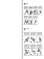
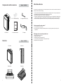
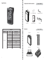
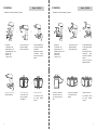
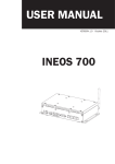
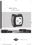
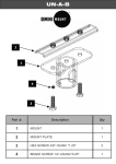
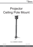
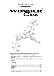
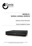
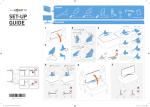
CONTENT
• Warning & Caution................................................................................................................................................. 3
• Components and Accessories & Overview............................................................................................................ 4
• Installation Procedures.......................................................................................................................................... 5
• Specification........................................................................................................................................................... 8
• After Sales Service................................................................................................................................................. 9
Warning
Private installation is restricted.
The user should request installation to a
specialist in a local agency to avoid any
type of accident during and after
installation.
Do not install the unit toward
deflection of sunlight to avoid
malfunction or defective image.
Turn off the unit when smoke or
unusual heat is found while using this
product and contact local agency.
This symptom might cause fire.
Do not place the unit where moist, oil
or gas is exposed to avoid
malfunction or electric shock.
Do not disassemble or put in alien
substance into the unit.
Do not hold the power plug with wet
hand.
It might cause malfuction or fire.
It might cause electric shock
Do not install the unit on soft material
to avoid dropping down from the wall.
Precaution
Do not install under extreme temperature conditions.
Do not install under unstable lighting conditions.
Do not drop the illuminator or subject it to physical shock.
Do not touch the illuminator lens.
Never keep the illuminator face to strong light directly.
Do not put obstacle in front of product.
3
Components and Accessories
Model : VWL60-60
After Sales Service
This information is provided to ensure your safety and prevent any losses, financial or otherwise. Please read it
carefully and use the product accordingly.
2. 1/4” - 20UNC Bolt (3EA)
3. Hexagon Wrench (1EA)
• For product inquiries, please contact the retail shop where you bought the camera. The using of equipment such
as aerial ladder while providing after-sales service shall be at your expense.
• Separate the power plug when thunder crashes or lighting flashes.
• This product is support equipment for surveillance system. Therefore, we can’t compensate for material loss and /
or personal injuries by robbery, fire, natural disaster or something like this type. There are many cases that the
malfunction caused by inexperienced user and it is easy to fix the trouble by reading the trouble shooting only.
How to request after sales service?
1. Submit the defective model number
2. Submit the Warranty card along with defective product to classify the gratuitous repair and repair with
compensation
1. VWL60-60
4. Instruction manual
Overview
4
5. Adaptor
Model : VWL60-60
Front View
Side View
Bottom View
Rear View
Followings are the cases of repair with cost
1. Malfunction caused by user’s fault
2. Irregular power connection
3. Disassemble, repair by unprofessional user
4. Loss by robbery, fire natural disaster or something like this type
5. Replacement of consumption goods
9
Specification
Components and Accessories
1. VWL60-60
Overview
VWL60-60
SECTION
IR Illuminator
8
ITEM
SPECIFICATION
Lens
1 Aspheric Collimate Lens
Beam Angle
60˚
View Range
60m at 0.0Lux (1 Unit)
Wave Length
Cold White
Emitting Device
High Density Hybrid LED Semi-permanent
Operating Temp
-20˚C ~ 60˚C (In door / Out door)
Operating Humidity
90%Rh
IP Rating
IP67
Power
16V DC 1.5A
Dimension
111 (W) x 153.5 (L) x 98.47 (H) mm
Weight
1.0kg (Max)
Model : VWL60-60
2. 1/4” - 20UNC Bolt (3EA)
3. Hexagon Wrench (1EA)
4. Instruction manual
5. Adaptor
Model : VWL60-60
Front View
Side View
Bottom View
Rear View
5
Installation
Model : VWL60-60
- Connection of 2 units with bracket _Optional
Components
- Joint Bracket : 2EA
- Middle Bracket : 1EA
- Wall Mount Bracket : 1EA
- M6 Bolt : 8EA
- M8 Bolt : 4EA
- L Wrench : 2EA
Connect 2pcs of Joint
Brackets to Middle
Bracket with M6 Bolt.
Installation
Model : VWL60-60
- Connection of 3 units with bracket _Optional
Connect Middle Bracket
to Wall Mount Bracket
with M6 Bolt.
Depanding on the user’s
convenience,
middle
and bottom connections
allowed.
Components
- Joint Bracket : 4EA
- Middle bracket : 1EA
- Wall Mount Bracket : 1EA
- M6 Bolt : 8EA
- M8 Bolt : 8EA
- L Wrench : 2 EA
Connect 4pcs of Joint
Brackets to Middle
Bracket with M6 Bolt.
Connect Middle Bracket
to Wall Mount Bracket
with M6 Bolt.
Depending on the user’s
convenience,
middle
and bottom connections
allowed.
Control the angle with
Wall Mount Bracket.
Control the angle with
Wall Mount Bracket
6
Connect the product
on both sides of the
unit to joint bracket
using M8 bolt.
Complete connection.
It is possible to control
the
angle
between
products.
Connect the production
both sides of the unit to
joint bracket using M8
Bolt.
Connect 3 units products
to Joint Bracket using
M8 Bolt.
Complete connection.
It is possible to control
the
angle
between
products.
7