1
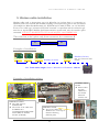
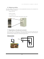
P D
E L E C T R O N I C S
C A B L I N G
1
Volume
INSTALLATION OF HPAC UNITS
Cabling general overview in order to improve the EMC
INDEX OF CHAPTER 1:
Hirobus Cabling
1. INTRODUCTION .................................................................................................. 2
2. EMC - ELECTROMAGNETIC COMPATIBILITY............................................. 3
3. HIROBUS CABLE INSTALLATION.................................................................... 4
4. HOW TO MAKE A NETWORK WITH HIROBUS ............................................ 6
5. SCREENED POWER SUPPLY CABLE ............................................................... 9
6. OUTGOING CABLES ......................................................................................... 10
7. DUPLICATION OF EXTERNAL CONTACTS .................................................. 10
8. RC FILTERS INSTALLATION .......................................................................... 11
9. SPECIAL INTERVENTION................................................................................ 11
1
P D
E L E C T R O N I C S
H I R O B U S
C A B L I N G
1
Chapter
1. Introduction
This chapter has been produced to give technical guidelines on how to make a good installation
of a Hirobus network, with special attention to the wiring connections.
The information contained in this checklist is a mere complementing tool for the engineer whose
responsibility is to design and install the system: his personal qualification implies the capacity to
set up installations in accordance with the norms and laws of the country in which he operates.
This document will be kept updated in the Web-site www.hiross.it/pde.
2
P D
E L E C T R O N I C S
H I R O B U S
C A B L I N G
2. EMC - Electromagnetic Compatibility
What is it and how can it influence the system?
E
Mc or electromagnetic compatibility is the capability of the system to resist against external
disturbances and to minimise the emission of disturbances from inside. Liebert Hiross
air-conditioners are tested by a Competent Body : an air conditioner sample with normal
configuration is checked under electromagnetic disturbances and it has to overtake the
tests otherwise the units cannot be sold in the European market and in those markets where the
CE mark is required.
Looking at the specific controls, Liebert Hiross Microface is judged by the Competent Body
“immune” from disturbances conducted into the main power supply up to 4 KV. These
disturbances are characterised by high voltage and low energy and Microface is not normally
damaged by them. However, disturbances stronger than the tested ones can influence the
behaviour of the control in the following ways:
•
Fluctuation of temperature on those units where the PTC sensor is installed
•
Unit self reset
•
Unit shutdown
•
False alarm generation
The generation of spikes (disturbances) is something typical of switching systems (frequency
converters, triac controllers, inductive loads, UPSs, diesel generators …) and if they do not work
according to the levels defined by European standards (the same we use to test our units:
EN50081-1, EN50082-2) they could influence our control systems.
How to solve the problem
The best solution would be to limit the problem at the source but this is in most cases
impossible. The alternative is to avoid the disturbance to affect our unit through external
connections and/or the power supply cable. In particular what follows is a list of mandatory rules
to respect.
3
P D
E L E C T R O N I C S
H I R O B U S
C A B L I N G
3. Hirobus cable installation
Hirobus cables used to interconnect up to 16 Microface (or 8 when there is a connection to
Hirolink) need to be screened and installed according to the instructions given in the user manual
(for example see Microface & Hiromatic AC WXG160 cod. 271618/272038 - rev. 19/10/1999).
It has to be a cable type “connector TVK 0067 screened” or equivalent and the connector type
must be an 8-poles RJ45 Modular Jack Interconnection system with only the central 6 poles
connected. IT IS NOT ALLOWED TO CUT the cable and JOIN it with TERMINALS.
The cable has to be 1 piece only from connector A to connector B
A
B
Example of installation:
Hirobus (8 wires)
Hirobus (6 wires)
Max 10 m ( otherwise PSM
needed)
Max Total cables lenght : from 1 st Microface to Hiromatic: 300 mt
Example of installation wiring:
POWER CABLE
PATH:
v Please follow
the path
indicated in
the manual
delivered
with the unit
HIROBUS CABLE:
v The cable must be
SCREENED
v The screen of the cable must
be DIRECTLY
CONNECTED WITH THE
ELECTRICAL PANEL
PLATE (EARTH).
HIROBUS PATH:
v The power cables and
Hirobus have to be kept at
distance following
different paths
4
P D
E L E C T R O N I C S
H I R O B U S
C A B L I N G
The maximum cable length between the first Microface and the last Microface or Hiromatic has
to be of 300 meters maximum. The cables between the units have to be positioned not in the
same channels of switching exchange cables or power cables and they have to run far away from
any cable which could generate disturbances.
The recommended solution is to install the Hirobus cable inside a screened channel (it can be
simply a metal pipe). Obviously, it cannot be the one containing other cables, like the switching
exchange cable or power cables, because they represent one of the major disturbances sources
mentioned at page 3.
5
P D
E L E C T R O N I C S
H I R O B U S
C A B L I N G
4. How to make a network with Hirobus
Hirobus networks between Microfaces (LAN) are built with 6-wires cables.
8-wires cables are used to connect sensors (Humitemp, EEAP and Hirosensor 2T) and
Hiromatic to Microface or to a PSM ( the Power Supply Module is needed when Hiromatic is
required at a distance from Microface higher than 10 mt. In this case you should consider the
Hiromatic remote box which contains the PSM. The connection Microface-PSM is with a 6wires cable while inside the box the connection PSM-Hiromatic is realised with an 8-wires cable).
Example of connections:
HIROMATIC (BACKSIDE)
To Display:
(4 wires flat cable)
1
EPROM
MICROFACE or MICROFACE E
3
4
2
FERRITE
6
5
POWER SUPPLY MODULE (PSM)
1.
2.
3.
4.
5.
6.
Microface to Microface Display
Microface to Microface (LAN)
Microface to accessories
Microface to Hiromatic G
Microface to PSM
PSM to Hiromatic G
6
P D
E L E C T R O N I C S
H I R O B U S
C A B L I N G
CONNECTIONS existing in a HIROBUS CABLE TYPE
Microface / Hiromatic system
CONNECTOR
1. Microface Display to
Microface
4-wires flat cable
RJ9 Connector with 4 poles (4
positions- 4 contacs)
2. Microface to Microface
(LAN)
6-wires screened flat cable
RJ45 Connector with 8-poles (8
positions – 8 contacts with 2
poles on the sides not used)
3. Microface to accessories :
Humitemp, Hirosensor 2T
and EEAP sensors
8-wires flat cable; it must be screened RJ45 Connector with 8-poles (8
(and connected to the Earth) if the
positions – 8 contacts)
sensor is positioned outside the unit.
4. Microface to Hiromatic
(built on the unit)
8-wires flat cable
RJ45 Connector with 8-poles (8
positions – 8 contacts)
5. Microface to PSM (Power 6-wires screened flat cable
supply module) inside the
Hiromatic box. (therefore
Microface to Hiromatic box)
RJ45 Connector with 8-poles (8
positions – 8 contacts with 2
poles on the sides not used)
6. PSM to Hiromatic (already 8-wires flat cable
connected in the Hiromatic
Box)
RJ45 Connector with 8-poles (8
positions – 8 contacts)
N.B. All cables not staying inside the unit must be screened. All screened cables must be
connected to Earth on both sides.
WARNING: please note that a wrong connection could cause serious problems to the
electronic devices (Microface and Hiromatic); for this reason we strongly recommend you to
use only first quality products or to buy the cables directly from Liebert Hiross: set sizes or
loose cables and connectors are available, as well as building tools:
1
4-WIRES HIROBUS CABLE WITH 4-POLES CONNECTORS
Microface Display to Microface: the max length possible is 450 mm.
FOUR POLES MODULAR
JACK
FOUR WIRES FLAT CABLE
Standard cable with
Microface Display
Optional cable for
Microface Display
Part number
Length
41 cm
275598
7
Description
4 wires cable with 4 poles connector + ferrite
P D
E L E C T R O N I C S
H I R O B U S
C A B L I N G
6-WIRES HIROBUS CABLE WITH 8-POLES CONNECTORS
2
EIGHT POLES MODULAR
JACK (USE ONLY THE
CENTRAL SIX POLES)
5
Part number
275647
275637
275633
275638
275639
Length
3m
5m
10m
25 m
50 m
SIX WIRES SCREENED FLAT
CABLE
6 wires
6 wires
6 wires
6 wires
6 wires
Description
screened flat cable +
screened flat cable +
screened flat cable +
screened flat cable +
screened flat cable +
connectors
connectors
connectors
connectors
connectors
MM
MM
MM
MM
MM
8-WIRES HIROBUS CABLE WITH 8-POLES CONNECTORS
3
4
6
EIGHT WIRES FLAT CABLE.
USE SCREENED CABLE WHEN CABLE IS
RUNNING OUTSIDE THE UNIT OR IN CASE
OF TROUBLES MENTIONED IN PAG.3)
EIGHT POLES MODULAR
JACK
Part number
275607
275606
275608
275635
275636
275642
Length
1m
Description
8 wires flat cable + connectors MM (only inside unit)
2m
3m
5m
10 m
25 m
8 wires flat
8 wires flat
8 wires
8 wires
8 wires
cable + connectors MM (only inside unit)
cable + connectors MM (only inside unit)
screened flat cable + connectors MM
screened flat cable + connectors MM
screened flat cable + connectors MM
The codes for the loose cables, connectors and tools are:
Part number
1
2
3
4
5
275625
275626
275612
275641
275613
Lenght
By metre
By metre
(1 piece)
(1 piece)
(1 piece)
Description
6 wires screened flat cable
8 wires screened flat cable
8-poles connector
Clamping tool for 4 poles / 6 poles
Clamping tool for 8 poles
8
1
4
3
5
P D
E L E C T R O N I C S
H I R O B U S
C A B L I N G
5. Screened power supply cable
Power cables can be of different sizes; the size does not depend only on the absorbed power but
also on the distance between the distribution panel and the unit itself. In addition to that, the
power cable is in most cases double insulated, which makes the positioning and handling inside
the unit even more difficult.
For those installations where there is a big power supply cable, it is necessary to use an external
junction box to interface the cable coming from the Main Distribution Panel and going into the
Main disconnector switch.
The following examples are referring so some kind of unit installations in order to give some
general guidelines. Installations can also be different to the ones shown depending on the type of
units considered.
Examples of installation
POWER CABLE:
v The cable must be
SCREENED
v The screen of the
cable must be
CONNECTED
TO EARTH .
EXTERNAL
INSULATION:
v The cable external
insulation must be
removed, close to
the UNIT MAIN
SWITCH
9
POWER CABLE PATH:
v Please follow the path indicated in
the manual delivered with the unit
v The power cables and Hirobus
have to be kept at distance
following different paths.
P D
E L E C T R O N I C S
H I R O B U S
C A B L I N G
6. Outgoing cables
All cables coming out of the unit have to be screened and the screen has to be connected to an
earth terminal. Outgoing cables are:
1. Alarm relay cable
2. Remote on off cable
3. Fire shut down cable
4. Compressor status, fan status, electrical heater status cables
7. Duplication of external contacts
All contacts which are coming from outside, like the Remote on off, User input, Fire shut
down contacts, have to be connected to a relay inside the unit. The relay is then connected to
the relevant input. All relays have to be fitted with gold contacts.
Wiring example:
R1
User
contacts
Screen
R1
24 Vac
Air conditioner
10
P D
E L E C T R O N I C S
H I R O B U S
C A B L I N G
8. RC filters installation
RC filters need to be installed on coils and conductors (especially for those components which are
frequently activated, like fill-drain valves, electrical heaters contactors , etc).
Such installation is in most cases carried out in the factory but in case of disturbances on the
control system we suggest to check whether the unit components are equipped with RC or not.
Example of RC installation
RC Filter
Contactor
9. Special Intervention
Hirobus cables have 6 wires, 4 of which are used for communication, 1 is used to signal “ground”
and 1 could be used for network reset.
The Network Reset Pin is not managed by the control and in normal conditions it does not have
any influence on the system. However, in disturbed environments the presence of this pin could
influence the stability of the Microface-Hiromatic system.
Therefore only in those peculiar cases of anomalies in installations where everything is done
according to the instructions given in this Guide, we indicate the possibility to remove the pin n°3
from all the Hirobus cables (on both ends) present in the network. Such operation needs a very
skilful technicians and a special care to check that no Hirobus cable in the system is left with that
“unused” pin.
Example of Hirobus wiring
1 ST pin:Wire not-connected
2ND pin
3rd pin
4th pin:
5th pin:
6th pin:
7th pin:
GND
RESET
communication
communication
communication
communication
Hirobus 6 wires cable
8 pole multiplug,
view to the contacts
8 pole multiplug,
backside
8 TH pin:Wire not-connected
11