1
Not yet published in conferences or journals
3D-printing plates without “support”
Yasusi Kanada
Dasyn.com
When printing a plate (dish) using a 3D printer,
normally, so-called “support” material, which is disposed
after printing, is required to be printed and to support the
plate. However, try to create thin plates without using
such superfluous material! Some devices are required to
print them, but it is not so difficult.
one layer to the next layer. Such seams are highly visible
when printing a thin object such as a plate.
1. Printing plates by a conventional method
When creating something by using a 3D printer, first
we design it by a computer-aided design (CAD) software
tool, and generate a “model”. The “model” is represented
by a language format called STL. The model is sliced
into thin layers and divided into strings, and translated
into G-code, which is a language format used for 3D
printers.
The above process makes the design printable. A type
of 3D printer that layers melted plastic such as ABS or
PLA is called fused deposition modeling (FDM) type
printer. An FDM-type printer melts plastic into strings
(filaments), and layers them according to a G-code
program (Figure 1).
(a) Without support
(b) With support
Figure 2. Visualized G-code
Seams can be eliminated by printing helically instead
of layer-by-layer. The helical printing method
[Reference 1] enables this. This method not only
eliminates seams but also enables free (i.e., nonhorizontal) printing directions. This enables the direction
of filament extrusion expresses shape formation
[Reference 2]. However, it is out of scope of this article.
Figure 3 shows a plate printed by the helical printing
method. Because this plate is made of transparent PLA
and the printing direction and gradient of each part is
designed to light reflection to a different direction, the
plate reflects light to various directions and gives
brilliance. Support, which spoils brilliance, is not used
for this plate.
Figure 1. Process of FDM-type 3D printing
(“FDM by Zureks” by Zureks - Wikimedia Commons)
When printing a plate by using an FDM-type printer by
a conventional 3D printing method, round or overhung
part of the plate must be supported by printed material
that is called “support”. Figure 2 visualizes G-code that
represents plate only (a) and G-code that represents plate
and support (b). Support is disposed after printing, so it is
wasteful. The support in Figure 2(b) can be smaller, but it
may sometimes use more material than plate itself (For
displaying G-code in this figure, Repetier Host
(Macintosh version) is used).
Is there a method for shaping plates without support
that wastes plastic? It is difficult while using
conventional 3D printing methods. However, there are
two methods that enable it. The next two sections
introduce them.
Figure 3. A small plate printed by the helical printing
method
2. Shaping plates by helical printing method
A model to be printed is sliced into thin layers and they
are printed one by one in conventional 3D printing
methods. A “seam” is generated when transiting from
The process of printing a plate by the helical printing
method can be observed by a video in YouTube
1
Not yet published in conferences or journals
(http://youtu.be/5P1vaahzW98). Highly transparent PLA
is not usually used in 3D printing. However, pure PLA
(such as “PLAGO”) has high degree of transparency and
it is very attractive as filament for this type of 3D
printing.
More than ten types of small plates are sold at around
150 yen in “Dasyn” shop in Yahoo! shopping
(http://store.shopping.yahoo.co.jp/dasyn/
or
http://bit.ly/1EZ4SZI). This shop sells various goods that
include a transparent and empty globe shown in Figure
4. A more advanced printing technique is used in this
globe, so the author will introduce it in another
opportunity.)
(a) When the filament is
(b) When the filament is
orthogonal to overhang
parallel to overhang
direction ― filament
direction ― filament
drop-down
bending
Figure 5. Problems of 3D printing with high-angle
overhang
3.2 Outline of the solution
How can we solve the above-explained problem when
printing a plate? The solution is, in short, to increase the
amount of filament so that printed filament becomes
thicker and sticks to the neighbor filament. Normally, if
the layer thickness is 0.2 mm, the thickness of filament is
set to a slightly larger than 0.2 mm. However, in this
case, for example, it is set to 0.4 mm. It makes neighbor
filaments stick together. This solution is explained more
in the following.
3.3 Setting filament increase
The first step is that, by changing the configuration of
the slicer, the amount of filament is increased. There are
various slicers available, but Slic3r and Skeinforge are
selected as representatives here. Both programs are
widely used for 3D printing. The methods for increasing
filament depend on the program. (Slic3r works better for
printing a plate).
When using Slic3r, the value of parameter called
extrusion multiplier should be set to between 4 to 6
instead of normal value around 1.0. (This means the
amount of filament is 4 to 6 times larger).
Figure 6(a) shows the configurations for Slic3r. The
value of “extrusion multiplier” is set to 6 in the
configuration window of filament for Slic3r for
Macintosh. In this window, the following parameters are
also specified: the thickness of filament (1.75 mm), the
temperature of extruding filament (about 200°C for PLA
of good quality), and the temperature of print bed, i.e.,
the surface to start printing, (30°C, a temperature that
PLA fits well to the print bed).
Figure 6(b) shows the configurations for Skeinforge.
The value of “filament packing density” is set to 0.15 to
0.25 instead of normal value around 1.0. This means that
the filament is increased 1/0.25 to 1/0.15 times. This
figure shows that 0.25 is specified for Skeinforge for
Macintosh. If you use another slicer, you should follow
the own style of the slicer.
Figure 4. A small globe printed by the helical printing
method
The design method for the helical printing method is
different from that of the conventional 3D printing
method. So, although conventional 3D printers can be
used for this method, currently, it cannot be applied to
models designed by conventional CAD software tools.
Then, is it not possible to print plates without support
by using a software tool for conventional 3D printers?
Yes! Actually, there is a method to enable it. The next
section introduces this method.
3. Problems of printing plates and a solution
3.1 Problems of conventional 3D printing
The problem of conventional 3D printing of plates are,
as written above, is that it is not possible to print it
without support. Figure 5 shows what happens when
printing it without support. Figure 5(a) shows what
happens when the direction of overhang and filament
direction are orthogonal. The filaments drop down in this
case. Figure 5(b) shows what happens when the direction
of overhang and filament direction are parallel. The
filament bends downward in this case.
2
Not yet published in conferences or journals
0.4 mm
15°
0.4 sin15°
= 0.1mm
0.4 cos 15°
= 0.39 mm
Figure 7. Decision of layer height
(a) Slic3r ― changing extrusion multiplier
(a) When using Slic3r
(b) Skeinforge ― changing filament packing density
Figure 6. Slicer configuration change for increasing
filament
3.4 Configuration change of layer height
The next step is to change the configuration of the
slicer to adjust the layer height. The layer height is
usually smaller than the diameter of the nozzle, which
extrudes melted plastic. The nozzle diameter is usually
0.3 to 0.5 mm. If the diameter is 0.5 mm, normal layer
height is, for example, 0.4 mm. However, the layer height
is set to smaller value here.
The reason why layer height should be smaller is
explained as follows. Figure 7 shows part of a cross
section of a plate. It is assumed that the filament is
wound with the angle of 15° from the horizontal surface.
If the diameter of the filament is 0.4 mm (or slightly
larger), the difference of the heights from the neighbor
filament is 0.4 sin 15° (= 0.1) mm. The layer height
should thus be 0.1 mm. However, because the filament
location that the slicer chooses may be different, so the
height may have to be adjusted.
Figure 8 shows two windows for specifying the layer
height, i.e., Slic3r (a) and Skeinforge (b). The layer
height is 0.1 mm for both, but the first layer height is also
set to 0.2 mm for Slic3r. This is because, if the height of
the bottom layer is 0.1 mm too, it becomes difficult to
adjust the printer for successful printing.
(b) When using Skeinforge
Figure 8. Configuration change of slicer for specifying
layer height
4. Let’s design plates!
Now, let’s design a plate to be printed by using a CAD
software tool. That is, an STL file is prepared. Any CAD
program can be used, but OpenSCAD [Reference 3],
which is a free software tool, is used for example here. A
Japanese Kindle book [Reference 4] explains all the
programs including OpenSCAD used in this article.
Many CAD programs use graphical user interface
(GUI) to create 3D models. However, a model is
generated by a program by using OpenSCAD. This
method takes more time when creating a model at first,
i.e., writing a program, but once the program is created, it
has an advantage that it is easier to modify the model
3
Not yet published in conferences or journals
(program).
I am relatively accustomed to draw a two-dimensional
shape such as shown in Figure 5 or 7 by using a program
such as Microsoft PowerPoint, the method of drawing 3D
shapes by using a CAD program is usually quite different
so I am not accustomed to it. Therefore, I prefer to use
OpenSCAD.
Many different methods can be used for drawing a
plate by using OpenSCAD, but a relatively easy method
is to use a “cylinder” with different sizes of top and
bottom surfaces. That is, to use the following program.
(The mostly the same program is available at
http://www.kanadas.com/weblog/2015/02/cad.html
(or
http://bit.ly/173UG6b).
results. The STL file of the plate shown in Figure 9 can
be
downloaded
from
http://www.kanadas.com/weblog/ThinDish15.stl
(or
http://bit.ly/174wxfR). Because OpenSCAD cannot
display shapes very clearly, a free software tool called
netfabb Basic OpenSCAD was used for displaying the
plate in Figure 10. A slicer can convert this STL file to a
G-code program that can be executed (printed) by a 3D
printer.
Angle = 15;
R1 = 10;
R2 = R1 + 20 * cos(Angle);
H = 20 * sin(Angle);
difference() {
cylinder(h = H, r1 = R1, r2 = R2, $fn = 180);
translate([0, 0, 0.2])
cylinder(h = H, r1 = R1, r2 = R2, $fn = 180);
}
Figure 10. A plate designed by OpenSCAD
(displayed by using netfabb Basic)
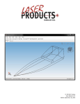
5. Let’s print the plate!
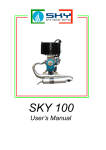
Now, let’s print the designed plate. I use a 3D printer
called Rostock MAX (Figure 11), but any other types of
3D printer can be used for this purpose. The nozzle
diameter of my printer is 0.5 mm. The time required for
printing the plate is about 6 minutes. However, to shorten
the printing time, the printing speed may have to be
changed by changing the configuration of the slicer.
In this program, an expression, cylinder(h = H, r1 =
R1, r2 = R2, $fn = 180), occurs twice. This expression
represents a “cylinder” with the radius of the lower base
is R1 and that of the upper base is R2, i.e., a plate filled
(with something like water). One of the cylinders is
placed 0.2 mm upper direction than the other by
translate([0, 0, 0.2]). The upper cylinder is subtracted
from the lower cylinder by difference(), so that the shape
becomes a plate (without water).
By executing the above program, a plate with less than
0.2 mm thickness is generated. It is so thin because each
layer consists of only a single wind of filament. The
thickness of printed plate will be more than 0.2 mm
because it is equal to the filament diameter. The
OpenSCAD window after the execution is shown in
Figure 9.
Figure 11. My 3D printer used for printing plates
(Rostock MAX)
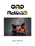
Figure 12 shows photos of the results of printing plates
with 15° gradient round by using Slic3r (a) and
Skeinforge (b). The layer height is 0.15 mm, which is
relatively thicker because the estimated filament diameter
is 0.56 mm (much larger than 0.4 mm). The amount of
filament is four times as much as the original value.
However, the amount of filament is still smaller than the
theoretical value; that is, the calculated diameter is less
than 0.56. (This is a mystery!) The photos seem to show
both worked well, but actually the filaments draw more
exact concentric circles in the case of Slic3r. In addition,
maybe because the layer height is too large, the stability
of printing seemed to be low and small-scale asperity
exists in this case.
Figure 9. OpenSCAD window after executing the
program
When using OpenSCAD, 3D models are represented by
programs and can be stored or modified freely, but they
can also be stored in STL format, which are execution
4
Not yet published in conferences or journals
Because the amount of filament is tuned to the round
with 15° gradient, the amount of filament is four times as
much as required at the bottom. However, the bottom still
seems to be good.
holes in this photo, but it just reflects light and it does not
have holes. In addition, although the holes cannot be
observed, there is a large hole between the bottom and
the round part. The bottom should be thicker (e.g.,
consists of three or more layers) by changing the design.
(a) When using Slic3r
(b) When using Skeinforge
Figure 13. Layer seams of printed plate
(layer height: 0.15 mm)
(a) When using Slic3r
Figure 14. Printed plate with 15° gradient round
(layer height: 0.135 mm, using Slic3r)
(b) When using Skeinforge
Figure 12. Printed plate with 15° gradient round
(layer height: 0.15 mm)
In addition, Figure 15 shows the results of printing
plates with 30° and 45° gradient round. In both cases,
Slic3r was used. The layer height was 0.25 mm and the
extrusion multiplier was 2.5 for the former and the layer
height was 0.35 mm and the extrusion multiplier was 1.5
for the latter. Both are well printed except the seams.
The major problem in these print results is the layer
seam. You can probably see the seam in the left side in
both Figures 12(a) and 12(b), but they are not very clear.
So Figure 13 zooms into the seam. Especially in Figure
13(b), i.e., in the case of Skeinforge, several gaps that
spoil the plate can be observed around the seam, but they
can also be observed in Figure 13(a), in the case of
Slic3r. Compared with the helical printing method, in
which no such seams or gaps are generated, they can be
regarded as a fatal defect. However, it is probably
possible to conceal them by using an advanced method. I
have not yet tried, but why don’t you try to print a better
plate? In addition, you can probably more easily see that
the filament arrangement (array) is better for Slic3r by
this figure.
The asperity had become smaller except the seams
when the layer height is set to 0.135 mm. Figure 14
shows a photo of a plate using Slic3r. The estimated
filament diameter is still 0.50 mm, but the seams have
become bumpier. Although this plate seems to have
6. Concluding Remarks
3D printers are widely used and studied in companies
in Japan. Especially, FDM-type printers gradually
become familiar to personal users. Although few personal
users have their own 3D printers, they can use 3D
printers by rentals in FabLab or DMM.MAKE.
Most of people who use 3D printers use CAD tools in
the conventional method. However, there must be many
more different ways to use 3D printers, i.e., different
printing methods, design methods, and so on. This article
showed that a new method for printing a plate without
support. As described in Section 2, I tried a completely
different method called the helical printing method, but
the method introduced in this article is a compromised
5
Not yet published in conferences or journals
method, i.e., pseudo layered method. There must be other
much more interesting methods. Why don’t you try one?
(a) When the gradient is 15°
(b) When the gradient is 30°
Figure 15. Printed plate with 30° gradient and 45°
gradient (by Slic3r)
References
[1] Kanada, Y., “3D-printing of Generative Art by using
Combination and Deformation of Direction-specified
3D Parts”, 4th International Conference on Additive
Manufacturing and Bio-Manufacturing (ICAM-BM
2014, Beijing), 2014-11, http://bit.ly/1zcMCaO
[2] Kanada, Y., “Method of Designing, Partitioning, and
Printing 3D Objects with Specified Printing Direction”,
2014 International Symposium on Flexible Automation
(ISFA 2014), 2014-7, http://bit.ly/1EqhV5d
[3]
“OpenSCAD
User
Manual”,
WikiBooks,
http://en.wikibooks.org/wiki/OpenSCAD_User_Manua
l/
[4] Kanada, Y., “Assembling and adjusting a cheap 3D
printer Printrbot -- sweat and tears” (Japanese Edition),
Kindle
version,
Dasyn.com,
http://www.amazon.com/dp/B00D5DYME4/
6