Download ROTOSCAN RS4/PROFIsafe
Transcript
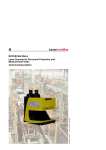
ROTOSCAN RS4/PROFIsafe
605054 - 2009/03
Subject to change without prior notice
Additional Information to Connecting and Operating
Instruction Laser Scanner ROTOSCAN RS4-4
CONNECTING AND OPERATING INSTRUCTIONS
About the Connecting and Operating Instruction
DEUTSCH
ENGLISH
The Connecting and Operating Instruction for the ROTOSCAN RS4/PROFIsafe Laser
Scanner contain all the information you need for the correct use, project configuration,
assembly, electrical installation and commissioning of scanners with a PROFIBUS connection. Additional information will be found in the RS4soft User Manual. Both these
documents, as well as the RS4soft software, form part of the RS4 setup set RS4-SWC, and
are intended for the use of planners, operators and maintenance personnel of systems
which are protected with the ROTOSCAN RS4/PROFIsafe Laser Scanner.
It is essential that all the instructions given in the Connecting and Operating Instruction and
in the User Manual be observed, especially those relating to safety.
The Connecting and Operating Instruction and the User Manual should be carefully looked
after. They must be available at all times throughout the period when the scanner is in use.
Safety instructions and warnings are indicated with the symbol
.
Instructions relating to the safety of laser equipment are indicated with the symbol
.
FRANÇAIS
L indicates information without any safety implications.
The Leuze electronic GmbH + Co.KG is not liable for damage resulting from
improper use. Acquaintance with these instructions constitutes part of the knowledge required for proper use.
© Reprint and reproduction, in whole or in part, only with the explicit permission from
Leuze electronic GmbH + Co. KG
Liebigstrasse 4
82256 Fuerstenfeldbruck / Germany
Phone +49 8141 5350-0
Telefax +49 8141 5350-190
[email protected]
www.leuze.com
ITALIANO
ESPAÑOL
NEDERLANDS
2
RS4/PROFIsafe
Leuze electronic
Contents
2
System architecture .......................................................................................................... 7
2.1
PROFIBUS DP..................................................................................................................... 7
2.2
PROFIsafe ........................................................................................................................... 9
2.3
The ROTOSCAN RS4 Laser Scanner ................................................................................. 9
2.4
The PROFIsafe adapter ..................................................................................................... 10
3
Safety instructions .......................................................................................................... 12
3.1
Hazardous consequences of failure to observe the safety instructions ............................ 12
3.2
Conditions and specifications of use ................................................................................. 12
3.3
Areas of use ................................................................................................................................14
3.4
3.4.1
3.4.2
3.4.3
3.4.4
3.4.5
Organisational measures ................................................................................................... 14
Documentation ................................................................................................................... 14
Safety prescriptions............................................................................................................ 14
Qualified personnel ............................................................................................................ 14
Repairs............................................................................................................................... 14
Disposal ............................................................................................................................. 15
4
Design, assembly and connection to the power supply ............................................. 16
4.1
Design ................................................................................................................................ 16
4.2
Mounting ............................................................................................................................ 16
4.3
Connecting the device to power supply ............................................................................. 17
4.4
Display ............................................................................................................................... 19
4.5
PROFIBUS address .....................................................................................................................20
5
Data structure................................................................................................................... 21
5.1
5.1.1
5.1.2
Cyclic data exchange ......................................................................................................... 21
Cyclic input data................................................................................................................. 21
Cyclic output data............................................................................................................... 23
5.2
5.2.1
5.2.2
5.2.3
Acyclic data exchange ....................................................................................................... 24
Header for acyclic commands............................................................................................ 26
Commands to the PROFIsafe adapter............................................................................... 28
Commands to the RS4....................................................................................................... 34
5.3
5.3.1
5.3.2
Alarms ................................................................................................................................ 40
Alarm update messages .................................................................................................... 41
Diagnosis alarms................................................................................................................ 41
6
Project configuration of the master ............................................................................... 44
Leuze electronic
RS4&PROFIsafe
3
ENGLISH
Symbols and terms .............................................................................................................. 5
FRANÇAIS
Certification .......................................................................................................................... 5
1.2
ITALIANO
TNT 35/7-24V
1.1
ESPAÑOL
General remarks................................................................................................................. 5
NEDERLANDS
1
DEUTSCH
Contents
Inhaltsverzeichnis
DEUTSCH
6.1
Hardware configuration by means of STEP 7.................................................................... 44
6.2
Configuration of the PROFIsafe driver by means of STEP 7............................................. 45
6.3
Diagnosis data ................................................................................................................... 48
6.4
Proxy Function Block (“FB RS4”)....................................................................................... 49
6.5
6.6
The user program ........................................................................................................................ 54
Response time ............................................................................................................................. 56
ENGLISH
7
Putting the system into operation, and replacing components .................................. 57
7.1
7.1.1
7.1.2
Behaviour of the system when switching on ...................................................................... 57
PC adapter not connected ................................................................................................. 57
PC adapter connected ....................................................................................................... 58
7.2
7.2.1
7.2.2
7.2.3
7.2.4
Scenarios ........................................................................................................................... 58
Putting the system into operation for the first time............................................................. 58
Changing the parameterisation.......................................................................................... 59
Switching on a parameterised device ................................................................................ 59
Device replacement ........................................................................................................... 59
FRANÇAIS
ITALIANO
7.3
Examples of system programming .............................................................................................. 60
7.3.1
7.3.2
Setting up the hardware configuration of the ROTOSCAN RS4 laser scanner ................. 60
The user program .............................................................................................................. 61
8
Testing .............................................................................................................................. 65
8.1
Tests before the system is first put into operation ............................................................. 65
8.2
Regular testing................................................................................................................... 65
8.3
Cleaning the window.......................................................................................................... 65
9
Technical specifications and dimensional drawings ................................................... 66
10
Standard delivery and order details............................................................................... 68
10.1
Standard delivery ............................................................................................................... 68
ESPAÑOL
10.2
Start-up Set........................................................................................................................ 68
10.3
Order details RS4/PROFIsafe and accessories RS4/PROFIsafe...................................... 68
11
Declaration of conformity ............................................................................................... 69
NEDERLANDS
4
RS4&PROFIsafe
Leuze electronic
General remarks
The RS4 safety surface scanner is an active opto-electronic protective device or AOPD of
type 3 as defined by EN/IEC61496-1 and (pr)EN/IEC61496-3. The PROFIsafe adapter is
an accessory to the RS4 which serves for the safe connection of the device to PROFIBUSDP.
Certification
The Laser Scanner ROTOSCAN RS4/PROFIsafe was developed and manufactured with
regard to the applicable European guidelines and standards. An EC prototype test
certificate as specified in EN/IEC 61496-1 und (pr)EN/IEC 61496-3 has been conferred by:
TÜV Süddeutschland Group1
Zertifizierstelle
Ridlerstr. 65,
D-80339 Munich
GERMANY
1.2
FRANÇAIS
Product
ENGLISH
1.1
DEUTSCH
General remarks
Symbols and terms
The following symbols are used in this document, and these are some of the terms that
occur:
Instructions relating to specific actions, informing the user of procedures to be
followed / settings to be made
C1, C2
Class 1 or class 2: classification of PROFIBUS masters based on their support of different telegram formats
Central Processing Unit
CRC
Cyclic Redundancy Check, the check sum in a data telegram
DB
Data block
Download
Transfer of parameters from the master to a slave
DPV0,
DPV1
Functional versions of PROFIBUS
DRa
Data record
F-CPU
Failsafe CPU
1.
NEDERLANDS
CPU
ESPAÑOL
¾
Technischer Überwachungsverein:
authority responsible for maintaining industrial standards.
Leuze electronic
RS4/PROFIsafe
ITALIANO
TNT 35/7-24V
1
5
General remarks
F-device
Failsafe device (when a malfunction is detected, it automatically goes into
safe mode)
DEUTSCH
ENGLISH
F-system
Fail-safe system consisting of F-devices and other components
FB
Functional block
GSD
Electronic datasheet relating to a device that includes the device’s communication parameters
LS
Laser scanner
Master
Control unit in a bus system, gives permission to slaves to access bus
MMC
Micro memory card
OSSD
Output signal switching device (safety-related switch output)
PC adapter Cable connection between the optical parameterisation and diagnosis interface of the RS4/PROFIsafe and the RS232 interface of a PC
PDU
Protocol data unit
FRANÇAIS
PROFIsafe Application profile of PROFIBUS safety devices, realised by means of a safety
software component, the PROFIsafe driver
ITALIANO
Proxy-FB
Functional block in the S7 master, which carries out automatic parameter adjustment by referring to the RS4/PROFIsafe
PF
Protective field
SFC
System function call
Slave
Unit subordinated to the master for communication purposes. The only messages it sends on the bus are answers to requests from the master.
PLC
Programmable logic control
Upload
Transfer of parameters from a slave to a master
WF
Warning field
µC1, µC2
Abbreviations referring to the two micro-controllers in the PROFIsafe adapter
a. German: DS = Datensatz.
ESPAÑOL
NEDERLANDS
6
RS4/PROFIsafe
Leuze electronic
System architecture
DEUTSCH
PROFIBUS DP
PROFIBUS is a manufacturer-independent, open field bus standard, with a wide area of
application in manufacturing and process automation context. Independence of the
manufacturer and openness are guaranteed by the international EN 50170 and IEC 61158.
PROFIBUS makes it possible for the devices of different manufacturers to communicate
with each other without any specially adapted interfaces, and is suitable both, rapid
applications where time is a critical factor and for complex communication tasks. Continuous technical improvement means that PROFIBUS will continue to be the ultimately
reliable industrial communications system of the future.
PROFIBUS offers the functionally graduated communication protocols (communication
profiles) DP and FMS. Depending on the area of application, RS-485, IEC 1158-2 or
optical fibre cables are available as physical profiles to facilitate the transfer of
information.
Up to 126 stations can be connected to PROFIBUS DP. These divide up the transfer
medium on a time-share basis. The configurable data transfer rate is 9.6 KBd to 12 MBd,
the maximum possible rate being limited by the length of the cable. The RS485 cables that
are most frequently used must have their ends terminated with a bus terminator(see the
section on accessories, section 10.3, M12 terminal plugs).
ENGLISH
2.1
System architecture
FRANÇAIS
2
Slave 1
Slave n
ESPAÑOL
The functional principle of PROFIBUS
NEDERLANDS
Bild 2.1-1:
Slave 2
ITALIANO
TNT 35/7-24V
Master-Token Transfer
Leuze electronic
RS4/PROFIsafe
7
System architecture
DEUTSCH
Access to the bus is controlled by means of a master-slave protocol, with overriding token
passing. What happens is that a master station generates a request to one of the slave
stations that are subordinate to it for communication purposes, and the latter reacts to the
master’s request by sending a response telegram. Only the master that is currently in
possession of the token is allowed to generate request telegrams. Passing the token brings
it about that bus control rights are switched cyclically between the master stations. As well
as peer to peer communication between a master and a slave, a master can also generate
what are known as broadcast telegrams (which are sent to the address 127): these will be
received and evaluated by all slaves simultaneously, but not acknowledged. With what are
known as modular slaves, the PROFIBUS telegram may carry information on the slot and
the channel as well as the slave address.
PROFIBUS DP incorporates two classes of master.
The class 1 master is the central component responsible for the polling/bus access
procedure, and carries out data exchange with the input/output devices (slaves). It defines
the data transfer rate, to which the slaves will normally adapt automatically, and controls
the exchange of the token with other masters. Several class 1 masters may operate in the
PROFIBUS DP system simultaneously. Typical class 1 masters are programmable logical
controls (PLCs) and PCs responsible for system control.
Class 2 masters are generally used as project configuration or visualisation devices, and
serve as auxiliary tools when starting up the system or for diagnosis.
Data exchange between the class 1 master and the slave may be cyclic or acyclic.
Cyclic data are read into the process imaging memory of the master in each bus cycle, or
written from there to the slaves. Normally no programming is required: all that is needed
here is a project configuration, that is to say, the allocation of the data of the master
process image to the corresponding data in the PROFIBUS slaves. The PLC program
simply accesses the data in the process imaging memory without “knowing” whether these
data are being input/output locally in the context of the PLC, or by way of a PROFIBUS
slave. PROFIBUS is responsible for the automatic cyclic exchange of information.
Acyclic exchange of data can be carried out by the master that has parameterised the
slave. This uses the READ and WRITE functions. Acyclic data transfer is used, for
example, in the transfer of parameter records from the master to the RS4/PROFIsafe
(download) or from the RS4/PROFIsafe to the master (upload).
Alarms represent a special case. The master will be notified of these in the context of cyclic
data transfer through the PROFIBUS status byte; the master then gets the actual alarm
information from the slave that has signalled by means of an acyclic telegram. This
information will then be written by the master to a memory area reserved for alarms
(SAP51) and can be subsequently evaluated by the application program.
ENGLISH
FRANÇAIS
ITALIANO
ESPAÑOL
NEDERLANDS
8
RS4/PROFIsafe
Leuze electronic
PROFIsafe is a functional extension of PROFIBUS DP, and makes it possible to operate
safety bus components along with non-safety-related standard components on the same
bus. PROFIsafe devices do not call for any kind of modification to the existing hardware
components, and can be integrated with existing systems without any problem.
The PROFIsafe driver is a software component that carries a TÜV1 certification. Above the
communication layers, it makes use of the functions of the PROFIBUS DP stack. Safety of
data transfer is achieved by means of the special structure of the user data as well as
including the actual safety data, these also incorporate a control byte, a serial number and
a further check sum. The destination address makes it possible to address a PROFIsafe
device uniquely, even in systems with several PROFIBUS lines, that is with multiple slave
addresses for similar devices. Only cyclic data are transmitted safely, i.e. are processed by
the PROFIsafe driver before transmission.
The ROTOSCAN RS4 Laser Scanner
1.
NEDERLANDS
The RS4 surface scanner is an opto-electronic protective device (AOPD) of type 3. It
transmits very short laser impulses, and measures the time until the impulse impacts on an
object and until the reflection reaches the RS4 receiver. The length of time enables the
device to calculate the distance between the object and the RS4. The scanning unit in the
RS4 rotates, and transmitts/receives a laser pulse at every 0.36°. This enables it to scan a
sector of up to 190°, with the RS4 situated at the midpoint.
The protective field that is to be monitored is limited by a user-defined curve around the
scanner, the maximum distance from this to the midpoint of the scanner being 4 metres. If
an object is detected between this boundary line and the scanner, thus violating the
protective field, the scanner will switch off its safety-related OSSD output, bringing the
hazardous movement to a standstill. While the device is operating, one of a maximum of 4
protective fields can be selected, by enabling one of 4 outputs.
German: Technischer Überwachungsverein: Technical Inspection Authority.
Leuze electronic
RS4/PROFIsafe
ITALIANO
TNT 35/7-24V
2.3
ENGLISH
PROFIsafe
ESPAÑOL
2.2
FRANÇAIS
For the project configuration of every PROFIBUS DP class 1 master and of every slave,
what is known as a an electronic data sheet GSD is required. This will be supplied by the
manufacturer of the master or the slave, and describes its properties from the point of view
of PROFIBUS. As well as including such PROFIBUS data as e.g.
• the data transfer rate supported
• the telegram length supported
• the quantity of input and output data
this file contains information about diagnosis signalling and specific device parameters.
DEUTSCH
System architecture
9
System architecture
DEUTSCH
Without reference to the parameters, the scanner may put out a warning signal that is not
safety-related, if a warning field defined by the user should be violated. This warning field is
coupled to the protective field in a fixed pairing. All protective field pairs, together with the
permissible switchings, will be adapted to the given application when the equipment is first
put into operation.
2.4
The PROFIsafe adapter
ENGLISH
The RS4/PROFIsafe consists of two components, the RS4 and the PROFIsafe adapter.
The PROFIsafe adapter is responsible for the connection to PROFIBUS, and is designed
as shown below:
Restart
Warn
OSSD1 SF1 .. 4
OSSD2
FRANÇAIS
µC1
RS232
µC1
ITALIANO
DPC31
PWR
ESPAÑOL
Restart
Bild 2.4-1:
PROFIBUS-DP
24VDC
PC-Adapter
Design of the PROFIsafe adapter
NEDERLANDS
10
RS4/PROFIsafe
Leuze electronic
Warning!
Although the data transfer is safe, the warning signal must not be used in a safety-related
manner, as it is not delivered by the scanner as a safe signal.
ENGLISH
The safety-related output signals OSSD1 and OSSD2 and the warning signal of the RS4 is
communicated to the PROFIBUS master (generally speaking a safety PLC) as one bit of a
safety telegram. The program of this safety interface must bring about the switching-off of
the hazardous movement (see section 7.3). The switching of the protective field pairs
during operation is managed by output bits of the safety PLC, which are transmitted via
PROFIBUS and the PROFIsafe adapter to the RS4 (protective fields 1 to 4). The restart
signal for the RS4 can be given either by means of a button that is locally linked to socket 1
(section 4.3) or via PROFIBUS in the form of a bit of the cyclic output byte (section 5.1.2).
The optical PC adapter is connected with the PROFIsafe adapter via the infrared interface.
The adapter forwards the telegrams to the RS232 of the RS4, so long as a parameter
matching with the Proxy-FB on the master is not currently running (section 5.1.2).
DEUTSCH
System architecture
NEDERLANDS
ESPAÑOL
ITALIANO
TNT 35/7-24V
Warning!
In sizing the dimensions for your application, it is essential that you take into account the
longer response time of the RS4/PROFIsafe as compared with an RS4 that does not have
a PROFIBUS connection (section 6.6)
FRANÇAIS
Note:
For the RS4/PROFIsafe, this document replaces the description of the connection to the
machine interface given in the RS4-4 Connecting and Operating Instruction.
Leuze electronic
RS4/PROFIsafe
11
Safety instructions
DEUTSCH
3
Safety instructions
3.1
Hazardous consequences of failure to observe the safety
instructions
ENGLISH
The products of Leuze electronic are developed and manufactured through the careful
application of the recognised rules of technology. The protective function of the equipment
can however be impaired if it is inappropriately used or used otherwise than in the manner
specified. In this case it may no longer be possible to protect danger areas, or protection
will be less than adequate. This may result in danger to life and limb for personnel who are
in close proximity to the machine or plant.
Warning: laser beam!
The RS4 laser scanner is a laser device of laser class 1. Please have regard to the
applicable statutory and local regulations for the operation of laser systems. Avoid
positioning the scanner at eye level.
FRANÇAIS
3.2
Conditions and specifications of use
ITALIANO
Use of the RS4/PROFIsafe surface scanner is governed by the relevant European
prescriptions relating to plant safety, in particular:
• Machinery Directive 98/37/EC and
• Directive on the Use of Working Equipment 89/655/EEC
as well as the corresponding national laws that have been implemented in the various
member states of the EU. In the Federal Republic of Germany the laws that apply are the
Plant Safety Act1 and the Ordinance on the Use of Working Equipment2, in association with
the Working Conditions Act3, statutory prescriptions for the avoidance of accidents, safety
regulations and any other relevant safety prescriptions and standards.
Observation of these regulations is obligatory for the manufacturer and operator of the
machine or equipment to which the opto-electronic protective device is attached. For the
clarification of safety issues the responsible local authorities (e.g. industrial control
authorities, professional trade associations or factory inspectorates) may be consulted. In
general terms the conditions of use to be observed are as given below.
The equipment may be set up and connected to the power supply only by qualified
personnel. The same goes for the testing that must be carried out before the equipment is
put into operation, and for regular testing subsequently. Knowledge of the safety instructions contained in this Connecting and Operating Instruction forms part of the qualifications
that the personnel are required to have. Special safety instructions relating to electrical
connection may be found in section 4.
The RS4/PROFIsafe conforms to safety category 3 as defined by EN954-1. In order to
maintain this level of safety, all elements in the safety chain that are installed on the
downstream side, right up to the stopping of the hazardous movement, must also conform
at least to the requirements of safety category 3.
ESPAÑOL
NEDERLANDS
1.
2.
3.
12
German: Gerätesicherheitsgesetz.
German: Arbeitsmittel-Benutzungsverordnung.
German: Arbeitsschutzgesetz.
RS4/PROFIsafe
Leuze electronic
ENGLISH
FRANÇAIS
ITALIANO
TNT 35/7-24V
NEDERLANDS
ESPAÑOL
The use of the RS4/PROFIsafe Laser Scanner is subject to the relevant prescriptions of
plant safety. For the clarification of safety issues the responsible authorities (e.g.
professional trade associations, OSHA etc.) may be consulted. In general terms the
conditions of use to be observed are as given below.
If the scanner is equipped with a protective housing, there should not be any further
window materials (plastic, glass etc.) in the path of the scanning beam.
Avoid touching the scanner window and the six scattered light panes.
The RS4/PROFIsafe Laser Scanner is not suitable as a protective facility in situations
where the overspill of dangerous liquids is a possibility, or where there are objects with long
machine braking times (max. depth of protective field 4 m). In cases like these Leuze
electronic can provide suitable door bolts (safety switches), either with or without guard
interlocking.
The 24 V DC power supply (which may vary from +20% to -30%) must be by means of a
safety transformer as defined by IEC 742. the same requirements apply to all incoming or
outgoing power circuits that are connected to the system.
The scanner is to be connected to the power supply by way of a separate branch and by
means of a 1.25 amp middle time-lag fuse installed in the switch cabinet.
The complete system (comprising scanner, machine, control and switching components)
may only be tested when no hazards to personnel will result from this.
Interfering with or modifying the RS4/PROFIsafe Laser Scanner can lead to a loss of its
safety functionality.
Putting the machine into operation, maintenance, setting of the parameters and configuration of the protective field are only to be carried out by properly qualified personnel.
Knowledge of the safety instructions of this Connecting and Operating Instruction and of
the User Manual contained in the RS4soft program forms part of the qualifications that
personnel are required to have.
The password required for the configuration of safety-related settings is to be kept secret
by the safety officer. Information about password levels will be found in the RS4soft User
Manual
The use of the scanner for monitoring the passage of persons (vertical protective field) as
defined by IEC 61496-3 is only permitted under the following conditions:
• non-detachable fixed mounting of the scanner
• non-removable walls for zoning the passage, which has to be protected
• response time of the entire protective device including PROFIBUS and PCL < 160 ms
DEUTSCH
Safety instructions
Leuze electronic
RS4/PROFIsafe
13
Safety instructions
3.3
Areas of use
DEUTSCH
ROTOSCAN RS4 Laser Scanners are primarily intended for the protection of danger
areas. To do this, for the most part horizontal scanning serves to check for the presence of
persons in the protective field at any time. When the RS4 is in use, access to the danger
zone should only be possible by passing through the protective field. Between the
protective field and the danger zone a defined safety distance must be maintained. This
may be calculated from the formulas in the specific machine-related European ‘C’
standards or in the general ‘B1’ standard EN 999. The RS4 is absolutely not suitable as a
protective facility when there is a risk that objects may be violently expelled or that hot or
hazardous fluids may spurt out. Nor is it suitable for machines with long overtravel times. In
cases like these Leuze electronic can provide suitable door bolts (safety switches), either
with or without guard interlocking.
ENGLISH
Warning!
When using the RS4/PROFIsafe, please be aware that the response time is higher than
that given in the ROTOSCAN RS4 Laser Scanner Connecting and Operating Instruction,
and this will have implications for the permitted distance from the danger zone (see also
section 6.6).
FRANÇAIS
3.4
Organisational measures
3.4.1
Documentation
ITALIANO
It is essential that all the instructions of this Connecting and Operating Instruction be
observed, especially those given in chapters 2 and 7. Keep this Connecting and Operating
Instruction in a safe place. It should be available at all times.
Regard must also be had to the ROTOSCAN RS4 Laser Scanner Connecting and
Operating Instruction, which describe the function of the laser scanner.
3.4.2
Safety prescriptions
You should have regard to the statutory regulations that apply locally and to the
prescriptions of professional trade associations.
3.4.3
Qualified personnel
ESPAÑOL
The equipment should be installed, put into operation and maintained only by professionally qualified personnel. Electrical work may only be carried out by qualified electricians,
who must also have the required familiarity with the RS4soft software.
3.4.4
Repairs
NEDERLANDS
Repair work, especially involving the opening of the housing, may only be carried out by the
manufacturer or by a person acting with the manufacturer’s authorisation. An exception to
this is the setting of the PROFIBUS address with the rotary control switch (see section 4.5).
14
RS4/PROFIsafe
Leuze electronic
Safety instructions
Disposal
NEDERLANDS
ESPAÑOL
ITALIANO
TNT 35/7-24V
FRANÇAIS
ENGLISH
Note:
Electronic scrap is special category waste! Please observe the locally valid prescriptions
for the disposal of such waste! Neither the RS4/PROFIsafe Laser Scanner nor the
PROFIsafe adapter contain any batteries or other materials that need to be removed before
the equipment is disposed of.
DEUTSCH
3.4.5
Leuze electronic
RS4/PROFIsafe
15
Design, assembly and connection to the power supply
4
DEUTSCH
4.1
Design, assembly and connection to the power supply
Design
The RS4/PROFIsafe consists of two components, the RS4 laser scanner and the
PROFIsafe adapter. These have already been assembled together at the factory. The
PROFIsafe adapter manages the processing of standard RS4 data for PROFIBUS.
ENGLISH
1
2
FRANÇAIS
1 PROFIsafe adapter
2 RS4 laser scanner
Bild 4.1-1:
4.2
Design of the RS4/PROFIsafe
Mounting
ITALIANO
To mount the RS4/PROFIsafe you should use rather long fastening screws, with a length of
at least 50 mm and a diameter of 5 mm; in other respects the mounting instructions for the
RS4/PROFIsafe. The borehole measurements may be seen from the scale drawings in
section 9.
ESPAÑOL
NEDERLANDS
16
RS4/PROFIsafe
Leuze electronic
Design, assembly and connection to the power supply
4.3
Connecting the device to power supply
X2
X3
ENGLISH
X1
DEUTSCH
X5
X4
X1
Function
Restart button
Pin 1
Pin 2
Pin 3
Pin 4
Pin 5
n.c.
+24 V DC
n.c.
Restart
n.c.
out
X2
X3
PROFIBUS output
PROFIBUS input
in
VP
RxD/TxD-N
DGND
RxD/TxD-P
Shield
out
out
out
out
out
n.c.
RxD/TxD-N
n.c.
RxD/TxD-P
Shield
in
in
n.c.
n.c.
in
X4
Power supply
+24 V DC
n.c.
in
0 V DC
ITALIANO
TNT 35/7-24V
Socket/
plug
Connecting the RS4/PROFIsafe to the power supply
in
ESPAÑOL
Bild 4.3-1:
FRANÇAIS
X1 Restart button connection
X2 PROFIBUS output cable
X3 PROFIBUS input cable
X4Power supply
X5 Optical PC interface
NEDERLANDS
Tabelle 4.3-1: Terminal assignment of the RS4/PROFIsafe
Leuze electronic
RS4/PROFIsafe
17
Design, assembly and connection to the power supply
DEUTSCH
Plug X1 of the PROFIsafe adapter serves for the connection of a restart button. This button
serves first of all to unblock the startup/restart interlock that is internal to the scanner, if this
has been activated; in addition this button is responsible for the acknowledgement of error
messages. This is necessary if the scanner should malfunction.
When the restart button is activated, the safety outputs OSSD 1 and OSSD 2 of the RS4
are switched off, and the display on the scanner (LED 3) lights up red. The duration of the
reset signal must be from 0.12 to 5 seconds. The length of the restart cable must not
exceed 25 metres.
Shielded standard PROFIBUS cables, with the matching M12 PROFIBUS plug/socket, are
screwed onto socket X2 and plug X3. If the RS4/PROFIsafe is the last device connected to
PROFIBUS, a matching bus terminator must be connected to socket X2 (see section 10.3).
The RS4/PROFIsafe requires to be supplied via plux X4 with 24 V DC (which may vary
between +20 and -30%) from a mains source conforming to protective class 2 by way of a
unilaterally shielded supply line that should not exceed 50 m in length. The shield has to be
connected with the cabinet. Power is supplied to the RS4 laser scanner via the PROFIsafe
adapter.
For parameterisation purposes, and for local diagnosis of the RS4, a PC with the RS4soft
parameterisation and diagnosis software is connected to the top side of the PROFIsafe
adapter by way of an RS232 interface, the programming cable and the optical interface.
The cable exit of the PC adapter on the RS4/PROFIsafe thus points in the direction of the
protective field. A powerful magnet in the PC adapter not only brings about a mechanical
halt but at the same time informs a reed contact in the device that the PC adapter is
connected. The interface will only be linked to the RS4 if at the time no automatic
parameter matching with the optional Proxy-FB in the master is being carried out (section
6.4).
The PROFIsafe adapter does read the stream of data, but does not modify it in any way.
This interface thus corresponds in functional terms to the RS232 interface comprising SUBD plugs in the RS4.
ENGLISH
FRANÇAIS
ITALIANO
Note:
As the power supply for the PC adapter comes through the PC’s COM port, the latter must
be “RS232 compliant”, that is, with a load of 3 kOhm it must still be able to supply a voltage
of 5 V. The claim to be “RS232 compatible” that is occasionally found with Notebook PCs is
not sufficient here.
Note:
A complete description of the software may be found in the RS4soft User Manual.
ESPAÑOL
NEDERLANDS
18
RS4/PROFIsafe
Leuze electronic
ENGLISH
DEUTSCH
Design, assembly and connection to the power supply
FRANÇAIS
4.4
Connecting PC and RS4/PROFIsafe with optical PC adapter
Display
Below the surface on which the PC adapter is situated an LED is located, which displays
the status of the PROFIBUS connection. When the power is switched on, the PROFIsafe
adapter runs through an initialisation procedure, in the course of which the LED will give off
continuous light for two to three seconds. Rapid flashing (at a frequency of ca. 5 Hz)
indicates that the adapter is ready to set up the PROFIBUS connection. If the LED lights up
continuously for longer than 3 seconds, or if the flashing frequency is less than 5 Hz, this
indicates a malfunction. The varying flashing frequencies are intended to facilitate remote
diagnosis by the service technician.
NEDERLANDS
ESPAÑOL
Note:
If there is a malfunction but the LED does not indicate an error, the power supply should be
checked.
ITALIANO
TNT 35/7-24V
Bild 4.3-2:
Leuze electronic
RS4/PROFIsafe
19
Design, assembly and connection to the power supply
4.5
PROFIBUS address
DEUTSCH
After removing the 6 screws on the top of the PROFIsafe adapter, the lid of the adapter
may be taken off. This makes it possible to access the two hex switches which are used to
set the PROFIBUS address. HexL sets the lower-value four bits, and HexH the highervalue four bits of the PROFIBUS address. Addresses greater than decimal 126 (hex 7E)
are not allowed. This is ensured by not evaluating the highest value bit 7. The settings 127
(hex 7F) and 255 (hex FF) must not be used. The factory setting is address 4.
ENGLISH
Note:
What is known as the F_Dest_Add, which is necessary for the PROFIsafe protocol, does
not need to be set separately, as it results from the simple addition of 500 to the
PROFIBUS address. It is therefore only necessary, when configuring the system, to ensure
that in each of the PROFIBUS lines that are linked in a system each RS4/PROFIsafe has a
unique PROFIBUS address.
1
2
FRANÇAIS
1 HexL
2 HexH
ITALIANO
Bild 4.5-1:
PROFIBUS address switches
ESPAÑOL
NEDERLANDS
20
RS4/PROFIsafe
Leuze electronic
Data structure
The RS4/PROFIsafe supports both cyclic and acyclic data transfer. In cyclic operation, that
is to say, in each bus cycle, what are referred to as the cyclic input and output data are
exchanged between the master and the RS4/PROFIsafe. The terms “input and output
data” have reference to the master’s point of view. Thus • Input data are read by the master, are therefore data output by the RS4/PROFIsafe
• Output data are written by the master, and are the control signals for the RS4/
PROFIsafe.
The system supports the acyclic commands READ and WRITE, so that on the request of a
master large blocks of data can be transferred, either for parameterisation purposes or to
give a read-out of measurement data, without having a long-term adverse impact on cyclic
real-time operations.
5.1
Cyclic data exchange
DEUTSCH
Data structure
ENGLISH
5
Cyclic input data
The device supplies the safety master with input data of the length of 1 byte, having the
following structure:
6
5
Value
OSSD
Indicates the status of the RS4’s OSSDs
Warning
output
Error
Significance
0
At least one of the two OSSDs of the RS4 is off, or its signal could not be properly registered. It is possible to find
out the cause for the signal OSSD = 0 from bits 1 to 5.
1
Both OSSDs of the RS4 are switched on.
Replicates the status of the warning output of the RS4.
In the course of the parameterisation of the RS4 the warning “dirty
screen” should be assigned to the warning output.
0
The warning output has been set.
1
The warning output has not been set.
Indicates whether an error has occurred
(OSSD = 0 in case of error).
Information on the nature of the error will be found in section 5.3.2.
0
No error has occurred in the RS4 or in the PROFIsafe adapter.
1
An error has occurred in the RS4 or in the PROFIsafe adapter.
Tabelle 5.1-1: Cyclic input data
Leuze electronic
RS4/PROFIsafe
21
ITALIANO
TNT 35/7-24V
7
Designation
ESPAÑOL
Bit
NEDERLANDS
5.1.1
FRANÇAIS
After the parameters have been successfully set, cyclic data transfer will be started,
irrespective of the status of the RS4. The input data will be set to safe values, until the RS4
has started up, after which its set of parameters may be checked by the Proxy-FB.
Data structure
Bit
DEUTSCH
4
ENGLISH
3
FRANÇAIS
2
Designation
Value
Operating
status
Displays the operating status of the device
The RS4 may be parameterised either by way of PROFIBUS (C1
or C2 service) or by using the PC interface and the PC adapter.
RS232 active
Proxy
Request
ITALIANO
1
Protective
field
ESPAÑOL
0
Warning field
Significance
0
Normal protective operation
1
RS4 parameterisation status, RS4 initialisation phase, or
the automatic parameter monitoring has not yet taken
place or has not yet been completed; OSSD = 0.
Shows whether the optical PC adapter is connected to the RS232.
When the signal switches from 1 to 0, that is to say, when the PC
adapter is uncoupled, the Proxy Request bit (bit 2) will always be
set, so that the Proxy-FB can update its parameter settings in the
master if necessary.
0
No PC adapter is connected.
1
The optical PC adapter is connected. No RS4 parameterisation can be carried out by way of PROFIBUS; C1 and
C2 services will be acknowledged with an error message.
In the first setting of parameters, and during subsequent parameter
adjustment, the OSSD bit is set to 0. If during parameter adjustment the optical PC adapter is connected, the RS232 and bit 3 will
only be activated when the parameter adjustment has been completed. While this is going on, the RS4soft program on the PC cannot set up any connection to the RS4.
0
Monitoring of the parameter settings by the Proxy-FB
need not be carried out. At the start of parameter checking this bit is set to 0. If during the parameter checking
an error occurs, it will be reset to 1.
1
The RS4/PROFIsafe indicates to the Proxy-FB in the
master that it must request or supply the RS4/PROFIsafe’s parameters and validate them.
Shows that the protective field has been violated.
This bit must not be used for decisions with safety implications!
0
The protective field has not been violated.
1
The protective field has been violated.
NEDERLANDS
Shows if the warning field has been violated.
This bit must not be used for decisions with safety implications!
0
The warning field has not been violated.
1
The warning field has been violated.
Tabelle 5.1-1: Cyclic input data
22
RS4/PROFIsafe
Leuze electronic
Data structure
Warning!
Bits 0-6 must not be used for decisions that have safety implications. The failsafe PLC
must only evaluate bit 7 to release the machine that is connected on the outgoing side if
necessary.
5.1.2
DEUTSCH
The cyclic input data are transferred as PROFIsafe data with 16 bit CRC.
Cyclic output data
Value
Restart
Generates a restart signal on the restart line of the RS4
The timing that is defined for the RS4 must be guaranteed by the
PLC or by external sensors.
Proxy Enable
Significance
0
No restart pulse, line set to 0
1
The restart input of the RS4 is switched to 1 (restart
activated).
This bit determines whether, when the scanner is switched on or
when the scanner parameters are modified by way of the optical
PC interface, an automatic adjustment by the Proxy-FB will be
carried out. This bit will be evaluated when the PROFIBUS starts
up and when the optical PC adapter is uncoupled. In the user program it should be definitely assigned either to 1 or to 0.
0
The OSSD bit is released without the Proxy-FB having run. The Proxy Request bit in the cyclic input
byte (see section 5.1.1) will nonetheless be set, but
the master will not necessarily take this into account. No automatic parameter adjustment is possible when RS4/PROFIsafe is replaced.
1
The Proxy-FB is activated; automatic matching of
parameters between the master and the RS4/PROFIsafe will take place.
5
reserved
Expects the value 0
4
reserved
Expects the value 0
3
reserved
Expects the value 0
FRANÇAIS
6
Designation
ITALIANO
TNT 35/7-24V
7
ESPAÑOL
Bit
ENGLISH
The RS4/PROFIsafe expects to receive output data from the safety master (PLC) with the
length of 1 byte, having the following structure:
NEDERLANDS
Tabelle 5.1-2: Cyclic output data
Leuze electronic
RS4/PROFIsafe
23
Data structure
Bit
DEUTSCH
2
1
0
ENGLISH
FRANÇAIS
Designation
Value
Protective
field number
Selects a protective field / warning field pairing on the RS4
The number of the protective field to be called up is expected to
lie in the range 1 to 4. Any other number would generate a switching error, and will not be forwarded to the RS4. If an invalid protective field number is supplied, the OSSD bit will be set to 0.
Approximately 500 ms after a valid protective field number has
been subsequently supplied, the OSSD bit will be released
again.
This does not mean that absolutely any protective fields from 1 to
4, as well as any kind of protective field switchings, are permitted,
as additional restrictions may be made by way of the RS4 parameterisation. The RS4soft software defines for the RS4 which
protective fields may be switched on and in what order, and
which protective field may be activated when the system is switched on.
The PROFIsafe adapter ensures that correct timing will be observed when switching. This means that the PLC program can – by
contrast with the description given in connection with the RS4 –
switch directly from one to another permissible protective field,
without activating both protective fields together for more than
one second at most.
The protective field number is coded as follows:
Significance
Protective field number
ITALIANO
Bit 2
Bit 1
Bit 0
1
0
0
1
2
0
1
0
3
0
1
1
4
1
0
0
Tabelle 5.1-2: Cyclic output data
The cyclic output data are transferred as PROFIsafe data with 16 bit CRC.
ESPAÑOL
Note:
As the PROFIsafe adapter always selects protective field 1 when PROFIBUS is starting up,
if you want to be able to start up (after occurrence of an error, or when switching on the
system) with any protective field, then in setting the RS4 parameters you must at least
authorise the switching sequences that follow from protective field 1.
5.2
Acyclic data exchange
NEDERLANDS
Acyclic data exchange is advantageous if relatively large quantities of data have to be
transferred rather infrequently. The overall load on the bus can in this way be kept
comparatively low, which ensures that the real-time functioning of the cyclic telegrams can
be maintained. The READ and WRITE commands enable you to transfer acyclic PROFIBUS data, for instance in order to make a comparative adjustment of parameter settings, to
read out measurement data from the scanner or to transmit control commands.
24
RS4/PROFIsafe
Leuze electronic
ENGLISH
NEDERLANDS
ESPAÑOL
ITALIANO
TNT 35/7-24V
Note:
A faulty command to the RS4 in the course of normal operations can trigger an error in the
RS4, so that this will be put into safe mode (OSSD = 0).
FRANÇAIS
Class 1 master commands
The RS4/PROFIsafe requires the acyclic class 1 READ and WRITE commands for
automatic parameter matching, which is managed by the Proxy-FB (section 6.4). It is also
possible to generate RS4 commands using the safety master and to send these to the
scanner (section 5.2.3), having regard to the communication protocol and the safety
prescriptions. In addition to this, control commands for the PROFIsafe adapter can be
generated. These have the same format as RS4 commands (section 5.2.2).
Please be aware that acyclic communication based on the PLC user program is only
possible when the following conditions are fulfilled:
• The RS4/PROFIsafe must be in a normal state of operation.
• No PC adapter may be connected to the optical interface
(reed contact not activated).
• The Proxy-FB has concluded its data adjustment procedure.
So long as the PC adapter is connected to the optical interface, all acyclic WRITE
commands will be ignored. If the Proxy-FB has not yet finished its data adjustment
procedure, an acyclic command to the RS4/PROFIsafe that is generated by the user
program will result in the termination of the Proxy-FB’s processing, along with the delivery
of an error message. These commands, consequently, have to be synchronised with the
Proxy-FB (see section 6.4, FB_BUSY).
DEUTSCH
Data structure
Leuze electronic
RS4/PROFIsafe
25
Data structure
DEUTSCH
Class 2 master commands
All RS4 commands may be used as class 2 master commands (section 5.2.3), but not the
special commands for the PROFIsafe adapter that are designed to control the automatic
configuration (section 5.2.2). All commands are transmitted to and from the RS232 of the
RS4 transparently. Communication by means of class 2 commands is only permitted for
one master at any given time.
5.2.1
Header for acyclic commands
ENGLISH
Commands that are to be relayed to the RS4 on an acyclic basis may need more than 240
bytes, so that they must be broken up into several blocks. To ensure a consistent telegram
format, every data block that is transmitted acyclically (including those that do not need as
many as 240 bytes) will be introduced by a header. This header (see table below) replaces,
in an RS4 command, all RS232-specific formattings (starting identifier, terminal identifier,
labelling of two consecutive zeroes by means of subsequent 0xff and the check character).
Byte
Description
FRANÇAIS
1
Data flow control byte (see table 5.2-2)
2
Block length in bytes, including header
3
Higher-value byte (most significant byte) of the number of the data block, beginning with zero; the last block is always assigned the number 0xff (even when the
first and the last block are identical).
4
Low-value byte (least significant byte) of the number of the block, beginning with
zero; the last block is always assigned the number 0xff (even when the first and
the last block are identical).
5 - 196 User data
ITALIANO
Tabelle 5.2-1: Header for acyclic command telegrams
As the RS4 needs up to 2 minutes to process data, the data flow control byte for the READ
command will be set by the RS4/PROFIsafe and must be evaluated by the master. With the
WRITE command the master sets this byte to zero.
ESPAÑOL
NEDERLANDS
26
RS4/PROFIsafe
Leuze electronic
Data structure
Bit
Significance
0
The RS4/PROFIsafe cannot handle WRITE commands. If a WRITE
command is sent to the RS4/PROFIsafe all the same, it will not be processed; instead an error signal will be entered in the error buffer and an
alarm sent to the master.
1
The PROFIsafe adapter is ready to write the first or the next data block.
0
This data block contains no user data.
1
This data block contains user data.
2
0
Reserved
3
0
Reserved
1
ENGLISH
0
Value
DEUTSCH
Both for READ and for WRITE, the individual bits in the data flow control byte will be set by
the RS4/PROFIsafe as follows:
0, 1, 0 The PC adapter is connected to the optical interface. In this mode acyclic
WRITE commands will be ignored; no error message will be given.
0, 1, 1 The Proxy-FB of the master is currently processing an acyclic command
(READ or WRITE). Any additional acyclic WRITE or READ command
will result in an error in the Proxy-FB’s process sequence. These errors
can be prevented by checking the FB output FB_BUSY on the master.
1, 0, 0 Normal operation: acyclic READ and WRITE commands can be transmitted, having regard to bits 0 and 1.
1, 0, 1 There is no active communication link in place. That is to say, there is no
link to a class 1 master and the PC adapter is not connected to the optical interface. This status report can only be given to a class 2 master.
0
Reserved
ESPAÑOL
7
ITALIANO
TNT 35/7-24V
0, 0, 1 It has not proved possible so far to set up a path of communication.
Can only be received by a class 2 master, if the PROFIsafe adapter has
not yet concluded the startup procedure.
FRANÇAIS
6, 5, 4 The communication status of the PROFIsafe adapter is displayed in these bits in
the form of a number.
NEDERLANDS
Tabelle 5.2-2: Structure of the dataflow control byte
Leuze electronic
RS4/PROFIsafe
27
Data structure
DEUTSCH
The maximum length for a data record is 240 bytes, the minimum length is 5 bytes. Only
slot 0 should be used. Either 2 or 3 may be used as an index; they will be treated in the
same way by the PROFIsafe adapter. If the master is not capable of handling dynamic data
record length, it is possible nonetheless by using these two indices to minimise the load on
the bus, in as much as short messages will be transmitted through a short data record (e.g.
DR2 (index 2)) and long messages through a long data record (e.g. DR3 (index 3)).
Which data record will be used is determined by the master. Only the data bytes described
in the header will be evaluated.
Apart from local parameterisation by way of the PC RS232 interface, PROFIBUS
parameterisation of the RS4 by means of the Proxy-FB of a class 1 master (with automatic
parameter adjustment) can only be carried out on the basis of acyclic READ and WRITE
commands.
In a later section the structure of acyclic commands will be examined in more detail. This
can be defined by the user. A distinction must be made here between commands for the
PROFIsafe adapter and commands for the RS4.
As the RS4/PROFIsafe requires commands in order to supply RS4 data, an RS4 data
record cannot be called up directly by means of a READ command. A complete RS4 data
query therefore consists of
• a WRITE, in which the master specifies which data it wants to read
• followed by a READ, through which the requested data, that have in the mean time been
supplied, will be read out.
On the other hand, some commands to the PROFIsafe adapter can be directly implemented with a WRITE command.
All the RS4/PROFIsafe command telegrams described below must in addition be started
by the header (Table 5.2-1) described earlier (master Æ RS4/PROFIsafe) or will have a
header supplied by the PROFIsafe adapter (RS4/PROFIsafe Æ master). Only the user
data will be described here. For this reason the numbering starts, in the tables below, with
byte 5, which is the first byte of user data.
ENGLISH
FRANÇAIS
ITALIANO
5.2.2
Commands to the PROFIsafe adapter
When any class 1 or class 2 telegram is received, the first byte will indicate whether it is
intended for the PROFIsafe adapter or for the RS4.
If the command byte (byte 5) is not one of those shown below, the telegram will be
forwarded, without any further checking, to the RS4. If the RS4 does not recognise the
telegram either, depending on the status of the RS4 either an error telegram will be the
response (RS4 goes into error mode), or the telegram will be simply ignored.
ESPAÑOL
NEDERLANDS
28
RS4/PROFIsafe
Leuze electronic
Description
5
0x93 =
6
Error specification : 0 = incorrect length, 1 = incorrect parameters
error in the telegram
7
Command byte of the faulty telegram
Tabelle 5.2-3: Response of the PROFIsafe adapter in case of error
Resetting the PROFIsafe adapter
Using the WRITE command shown below, the master can reset the PROFIsafe adapter.
Here is the request the master needs to make:
Byte
5
Description
0x94 = PROFI_CMD_RESET
Reset command to the PROFIsafe adapter, no additional parameters
Tabelle 5.2-4: PROFIsafe adapter – resetting
There will not be any response from the PROFIsafe adapter. Immediately on reception of
this command the resetting of the PROFIsafe adapter (in the form of a power-on reset) will
be executed. This means that the PROFIBUS connection will be interrupted for approximately two seconds. The RS4 will not be affected by this (for RS4 restart, see section 5.1.2).
5.2.2.2
Forwarding RS4 telegrams
On the basis of this WRITE command the master prescribes which RS4 data are to be
forwarded to the master by the PROFIsafe adapter. Here are the master’s request options:
Byte
Description
0x92 = PROFI_CMD_GET_RS4_DATA
Processing of the RS4’s telegrams
6
The bit combination determines what telegrams will be forwarded to the master.
Bit 0 = 1
Measurement value telegrams will be forwarded to the master
Bit 1 = 1
Alive telegrams will be forwarded to the master
Bit 2 = 1
Warning telegrams will be forwarded to the master
Bit 3 = 1
Error telegrams will be forwarded to the master
ESPAÑOL
5
FRANÇAIS
5.2.2.1
ITALIANO
TNT 35/7-24V
Byte
ENGLISH
If the telegram is intended for the PROFIsafe adapter, the length of the telegram and the
parameter area limits will be checked. If these are in error, an error telegram will be sent in
response. In case of erroneous master READ commands, the PROFIsafe adapter
response is :
DEUTSCH
Data structure
If this byte = 0, no further telegrams will be forwarded.
Leuze electronic
RS4/PROFIsafe
NEDERLANDS
Tabelle 5.2-5: PROFIsafe adapter – forwarding RS4 telegrams
29
Data structure
Byte
DEUTSCH
7
Description
0 = only one telegram will be forwarded to the master.
1 = the telegrams selected above will continue to be forwarded to the master (in
the case of measurement value telegrams, only use this facility if the master will
really read the telegram, otherwise the telegrams become obsolete.) Error – or
warning – telegrams will be sent by RS4 once only, so that these can only be reliably received if byte 7 = 1.
>1 = not permissible.
Tabelle 5.2-5: PROFIsafe adapter – forwarding RS4 telegrams
ENGLISH
FRANÇAIS
In response the selected telegram or telegrams will be dispatched. As the PROFIsafe
adapter can put a number of RS4 telegrams into intermediate storage, if the requested
telegram is found, a response will be immediately provided and can be read out. Only after
this has been downloaded by the master will a new telegram be supplied, on the basis of
the telegrams that have been received from the RS4 at the present time.
If measurement value telegrams are to be forwarded to the master on an ongoing basis,
and if the RS4 should generate an error or a warning message by telegram, this will be
stored in a second buffer for the master, if this also needs to be forwarded. This means that
even a slow master can both read out all measurement value telegrams and also receive
error and warning telegrams.
5.2.2.3
Determining the version of the PROFIsafe adapter
With this WRITE command, followed by a subsequent READ command, the master can
find out what version of the PROFIsafe adapter is in use. Here is the WRITE request of the
master:
Byte
ITALIANO
5
Description
0x90 = PROFI_CMD_GET_VERSION, version determination
Response of the PROFIsafe adapter to the following master READ command:
Byte
ESPAÑOL
Description
Response from the
PROFIsafe adapter
5
Version query response
0x90
6
PROFIsafe version (high byte)
1
7
PROFIsafe version (low byte)
0
8
PROFIBUS DP version (high byte)
1
9
PROFIBUS DP version (low byte)
0
Tabelle 5.2-6: PROFIsafe adapter: version determination
NEDERLANDS
30
RS4/PROFIsafe
Leuze electronic
Byte
10
Description
Response from the
PROFIsafe adapter
DPV1SL components (high byte)
0x11
DEUTSCH
Data structure
0x01 = V1SL_COMP_INSTALLED_C2
0x02 = V1SL_COMP_INSTALLED_C2_RQB_IFA
0x04 = V1SL_COMP_INSTALLED_IBC
0x08 = V1SL_COMP_INSTALLED_ASPC2
ENGLISH
0x10 = V1SL_COMP_INSTALLED_DPC31
0x20 = V1SL_COMP_INSTALLED_SPC3
0x40 = V1SL_COMP_INSTALLED_DPR
11
DPV1SL components (low byte)
0x0D
0x01 = V1SL_COMP_INSTALLED_C2
FRANÇAIS
0x02 = V1SL_COMP_INSTALLED_C0_RQB_IFA
0x04 = V1SL_COMP_INSTALLED_SUB_AL
0x08 = V1SL_COMP_INSTALLED_SUB_C1
0x20 = V1SL_COMP_INSTALLED_SUB_S7
12
DPV1SL main interface
6
13
DPV1SL function
5
14
DPV1SL bugfix
1
ITALIANO
TNT 35/7-24V
0x40 = V1SL_COMP_INSTALLED_SUB_SC
NEDERLANDS
ESPAÑOL
Tabelle 5.2-6: PROFIsafe adapter: version determination
Leuze electronic
RS4/PROFIsafe
31
Data structure
5.2.2.4
Reading out the most recent error of the PROFIsafe adapter
DEUTSCH
With this WRITE command, followed by a subsequent READ command, the master can
read out the most recent error from the PROFIsafe adapter. Here is the WRITE request of
the master:
Byte
5
Description
0x84 = PROFI_CMD_ERROR
Querying the fault that most recently occurred in the PROFIsafe adapter
Response of the PROFIsafe adapter to the master’s subsequent READ command:
ENGLISH
Byte
Description
5
0x84 = response for last error from slave
6
high byte error number in µC2
7
low byte error number in µC2
8
high byte of error number since the power was turned on in µC2
FRANÇAIS
9
low byte of error number since the power was turned on in µC2
10
high byte error number in µC1
11
low byte error number in µC1
12
low byte of error number since the power was turned on in µC1
13
high byte of error number since the power was turned on in µC1
ITALIANO
Tabelle 5.2-7: PROFIsafe adapter – reading out the most recent error
5.2.2.5
Reading out the error register of the PROFIsafe adapter
With this WRITE command, followed by a subsequent READ command, the master can
obtain a complete read-out of the error register of the PROFIsafe adapter. Here is the
WRITE request of the master:
Byte
ESPAÑOL
5
Description
0x91 = PROFI_CMD_GET_ERROR, querying the error register of the PROFIsafe adapter
NEDERLANDS
32
RS4/PROFIsafe
Leuze electronic
Data structure
Description
0x91 = response for all errors from the PROFIsafe adapter
6
Write index of the most recent error in µC2 that has been entered in the ring buffer
7
0 = error occurred in the most recent cycle
1 = error occurred earlier
8
Error number (high byte) for index 0 in ring buffer of µC2
9
Error number (low byte) for index 0 in ring buffer of µC2
10
Error number (high byte) for index 1 in ring buffer of µC2
11
Error number (low byte) for index 1 in ring buffer of µC2
...
...
...
...
46
Error number (high byte) for index 19 in ring buffer of µC2
47
Error number (low byte) for index 19 in ring buffer of µC2
48
Write index of the most recent error in µC1 that has been entered in the ring buffer
49
0 = error occurred in the most recent cycle
1 = error occurred earlier
50
Error number (high byte) for index 0 in ring buffer of µC1
51
Error number (low byte) for index 0 in ring buffer of µC1
52
Error number (high byte) for index 1 in ring buffer of µC1
53
Error number (low byte) for index 1 in ring buffer of µC1
...
...
...
...
88
Error number (high byte) for index 19 in ring buffer of µC1
89
Error number (low byte) for index 19 in ring buffer of µC1
ITALIANO
TNT 35/7-24V
FRANÇAIS
ENGLISH
5
Tabelle 5.2-8: PROFIsafe adapter – reading out data from the error register
NEDERLANDS
The content of the error register is maintained intact when the system is restarted, but is
lost when the device is switched off.
ESPAÑOL
Byte
DEUTSCH
Response of the PROFIsafe adapter to the master’s subsequent READ command:
Leuze electronic
RS4/PROFIsafe
33
Data structure
5.2.3
Commands to the RS4
DEUTSCH
The RS4 commands described below use so called option bytes, that is to say control flags
carrying e.g. status information, which are transmitted along with each message. The first
option byte is always transmitted, and defines protocol information, such as for instance the
number of option bytes that are being transmitted. All the other optional characters will only
be transmitted when this is necessary, i.e. when at least one status bit is set. The three
possible option bytes have the following structure:
Name
Description
ENGLISH
Option 1 Option 1 is always sent, and has the following layout:
7
6
5
4
3
2
1
0
Bit
number of optional
fields, i.e. at least 1
FRANÇAIS
current operating
status
ITALIANO
0 = without password
1 = with password
0 = without acknowledgement
1 = with acknowledgement
reserved
ESPAÑOL
The number of option bytes can only lie between 1 and 3 (bit 0 & bit 1).
The current operating status field (bits 2-4) shows the current operating status, and has the following layout:
000 – no information (with messages to the RS4)
001 – initialisation
010 – measurement operations
011 – configuration
100 – error/malfunction
As the number of option bytes has to be at least 1, option 1 can never have
the value 0x00.
NEDERLANDS
Tabelle 5.2-9: Structure of the option byte in RS4 commands
34
RS4/PROFIsafe
Leuze electronic
Data structure
Name
Description
6
5
4
3
2
1
0
Bit
ENGLISH
7
DEUTSCH
Option 2 Option 2 transmits status information about the individual protective fields +
malfunction + warning + restart interlock.
It will only be transmitted if at least one flag is set, i.e. this byte can never
have the value 0x00. If this option is transmitted, the number of optional
fields in option 1 must be at least two. This optional character has the following layout:
currently active
protective field
0 = free
1 = occupied
currently active
warning field
0 = free
1 = occupied
FRANÇAIS
warning
malfunction
restart interlock
ITALIANO
TNT 35/7-24V
2nd protective field
0 = free
1 = occupied
2nd warning field
0 = free
1 = occupied
= 1 (for option 3)
ESPAÑOL
With messages to the RS4 this option byte has no significance. Bit 7 will be
set to 1 if option 3 has to be transmitted, so as to make it impossible for option 2 to have the value 0.
NEDERLANDS
Tabelle 5.2-9: Structure of the option byte in RS4 commands
Leuze electronic
RS4/PROFIsafe
35
Data structure
Name
Description
DEUTSCH
Option 3 Option 3 transmits status information about the selected protective field
pairs. It will only be transmitted if at least one flag is set, i.e. this byte can
never have the value 0x00. If this option is transmitted, the number of optional fields in the option 1 byte must be at least three. This option byte has
the following layout:
7
6
5
4
3
2
1
0
Bit
ENGLISH
1st selected protective field pair
FRANÇAIS
2nd selected protective field pair
ITALIANO
reserved
=1
ESPAÑOL
As it can happen that when the protective fields are being switched two protective field pairs may be selected simultaneously, it is necessary to give
two specifications for the selected protective field pair.
For the selected protective field pairs,
0 means that no selection has been made,
1-4 indicates selection of protective field pairs 1-4.
With messages to the RS4 this byte has no significance.
Tabelle 5.2-9: Structure of the option byte in RS4 commands
NEDERLANDS
36
RS4/PROFIsafe
Leuze electronic
Data structure
Description
5
0x14 = COM_CMD_ALIVE
6
Option 1
7
Option 2
8
Option 3
ENGLISH
Byte
Tabelle 5.2-10: Structure of the alive telegram
If no RS4 telegram is available, a block without data content will be sent.
5.2.3.2
DEUTSCH
Alive telegrams
When alive telegrams are enabled with PROFI_CMD_GET_RS4_DATA (see section
5.2.2.2), the master can read these in the following format:
Error telegrams
If an error occurs in the RS4, the following command will be sent as an alarm (section
5.3.2) or else sent to the master in response to an acyclic READ command.
5
0x53 = COM_CMD_ERROR_OCCURRED
6
Option 1
7
Option 2
8
Option 3
9
RS4 error number (high byte)
10
RS4 error number (low byte)
11
RS4 error parameter (high byte)
12
RS4 error parameter (low byte)
13
RS4 error function (high byte)
14
RS4 error function (low byte)
ITALIANO
TNT 35/7-24V
Description
ESPAÑOL
Byte
FRANÇAIS
5.2.3.1
NEDERLANDS
Tabelle 5.2-11: Structure of the error telegram
Leuze electronic
RS4/PROFIsafe
37
Data structure
5.2.3.3
Warning telegrams
DEUTSCH
If the window of the RS4 becomes too dirty, the following command will be sent as an alarm
(section Diagnosis alarms) or else sent to the master in response to an acyclic READ
command.
Byte
Description
ENGLISH
FRANÇAIS
5
0x54 = COM_CMD_WARNING_OCCURRED
6
Option 1
7
Option 2
8
Option 3
9
RS4 error number (high byte)
10
RS4 error number (low byte)
11
RS4 error parameter (high byte)
12
RS4 error parameter (low byte)
13
RS4 error function (high byte)
14
RS4 error function (low byte)
Tabelle 5.2-12: Structure of the warning telegram
5.2.3.4
Measurement value telegrams
ITALIANO
When alive telegrams are enabled with PROFI_CMD_GET_RS4_DATA, if the RS4 sends
measurement value telegrams the master can read these in the following format:
Byte
Description
5
0x23 = COM_CMD_MESS_16_RT
6
Option 1
7
Option 2
8
ESPAÑOL
9 ...
Option 3
User data (see below)
Tabelle 5.2-13: Structure of the measurement value telegram
The number of bytes of user data is dependent on the parameterisation of the RS4. If no
RS4 telegram is available, a user data block without data content will be sent.
NEDERLANDS
38
RS4/PROFIsafe
Leuze electronic
Every outline measured has 529 measurement values (angle of -5.04° to +185.04° with
0.36° resolution). Every individual measurement value has a segment number beginning
with 0. This means that the measurement value at the -5.04° point has the segment
number 0, and the measurement value at the 0° point has the segment number 14. Within
a measurement message it is not necessarily the case that all values of the outline
measured will be transmitted (see resolution, output start and output stop below). The
following data will be transmitted within a measured outline:
Sizes
17
Resolution
Gives the distance in segments (measurement points)
1 byte
between two consecutive measurement values. For example, the measurement outline is output, starting from
measurement value 0 through to 528, and the resolution
is set to 4. Measurement values will be output for the following segments of the outline measured:
0
4
...
524
528
18
Output start Indicates at which segment (between 0 and 528) the
measured outline of the output starts.
ENGLISH
With every revolution of the RS4, the scan number will be 8 bytes
incremented. This scan number can be used to determine
the distance in time between two measurement contours
that have been output.
The actual scan number has a size of 32 bits. So as to rule
out the possibility of a small value producing a multiple
zero in the transmission of these 4 bytes, filler bytes are
inserted between the individual bytes of the scan number.
This results in the scan number having the following structure:
Bits 24-31
0xFE
Bits 16-23
0xFE
Bits 8-15
0xFE
Bits 0-7
0xFE
FRANÇAIS
Description
Scan number
ITALIANO
TNT 35/7-24V
Name
9
2 bytes
NEDERLANDS
Tabelle 5.2-14: Structure of the measurement data in the measurement value telegram
ESPAÑOL
Byte
DEUTSCH
Data structure
Leuze electronic
RS4/PROFIsafe
39
Data structure
Byte
Name
Description
Sizes
DEUTSCH
20
Output stop Indicates which segment (between 0 and 528) supplies
2 bytes
the last measurement value. If the relation between the
number of measurement values output (resulting from
output start and output stop) and the resolution is not exact, then the measurement value corresponding to output
stop will be output as well.
22
Measurement values
ENGLISH
FRANÇAIS
In succession, the individual measurement values are
transmitted, starting with the measurement value that corresponds to output start and ending with the measurement value that corresponds to output stop.
Each measurement value here corresponds to the distance measured between the RS4’s rotational axis and
object at the given angular position, in millimetres.
Bit 0 of each measurement value indicates whether between the given measurement value and the previous one
the measured outline has violated a protective field. This
means that when the measurement values are evaluated
as a value of distance, bit 0 has to be masked out.
Depending on
output
start
and
output
stop, 2
bytes in
each
case
Tabelle 5.2-14: Structure of the measurement data in the measurement value telegram
2-byte values within the measurement value telegram are transmitted with the high byte
coming first and the low byte second.
5.3
Alarms
ITALIANO
Alarms will be automatically transmitted by PROFIBUS to the master, if they are reported to
the master in the cyclic telegram in the PROFIBUS status byte. The master will then get the
actual alarm information from the slave that has reported it by means of an acyclic
telegram, and write it to a storage area reserved for alarms (SAP51). The application
program can then evaluate the alarm report, without having to call up these data by means
of an explicit READ command.
ESPAÑOL
NEDERLANDS
40
RS4/PROFIsafe
Leuze electronic
Data structure
Byte
Bit
Description
7
6
5
4
3
2
1
0
1
0
0
0
0
0
1
0
0
Length of the alarm PDU (including header) = 4
bytes
2
0
0
0
0
0
1
1
0
Type = alarm update
3
0
0
0
0
0
0
0
0
No slots (slot 0)
4
0
0
Sequ. no.
1
0
0
No alarm differentiation, with acknowledgement,
sequential numbers 0-7
DEUTSCH
Alarm update messages
If after a C2-initiate a class 2 master accesses the PROFIsafe adapter in order to write for
the first time, this will be communicated to the class 1 master by means of the alarm update
facility. The alarm update PDU is coded as follows:
ENGLISH
5.3.1
Errors and warnings of the RS4, as well as errors in the PROFIsafe adapter, will be
reported as PROFIBUS diagnosis alarms. Each new error will be reported as a new
incoming alarm. Errors that persist with a standing connection will be reported only once. If
the connection is broken off and cyclic data traffic is later resumed, the last error that has
occurred, if it is still found to be present, will be reported once more as an incoming alarm.
If no error is found for a minimum of 500 ms, an outgoing alarm will be sent. A sequential
modality for 8 alarms is supported, that is to say that up to 8 alarms can be held on the
PROFIsafe adapter’s intermediate storage before being fetched by the master. The
diagnosis alarm PDU is coded as follows:
Byte
Bit
Description
6
5
4
3
2
1
0
1
0
0
0
0
1
1
0
1
Length of the alarm PDU including header, dependent on the alarm
2
0
0
0
0
0
0
0
1
Type = diagnosis alarm
3
0
0
0
0
0
0
0
0
No slots (slot 0)
4
0
0
Sequ. no.
1
0
0
No alarm differentiation, with acknowledgement,
sequential numbers 0-7
5
1
0
0
0
0
1
0
0
Error code 0x84 = error from slave
6
x
x
x
x
x
x
x
x
High byte of µC2 error number
7
x
x
x
x
x
x
x
x
Low byte of µC2 error number
NEDERLANDS
7
Tabelle 5.3-2: Structure of the diagnosis alarm
Leuze electronic
RS4/PROFIsafe
ITALIANO
TNT 35/7-24V
Diagnosis alarms
ESPAÑOL
5.3.2
FRANÇAIS
Tabelle 5.3-1: Structure of the alarm update message
41
Data structure
Byte
Bit
Description
DEUTSCH
ENGLISH
7
6
5
4
3
2
1
0
8
x
x
x
x
x
x
x
x
High byte of the number of this error in µC2 since
the system was last started up
9
x
x
x
x
x
x
x
x
Low byte of the number of this error in µC2 since
the system was last started up
10
x
x
x
x
x
x
x
x
High byte of µC1 error number
11
x
x
x
x
x
x
x
x
Low byte of µC1 error number
12
x
x
x
x
x
x
x
x
High byte of the number of this error in µC1 since
the system was last started up
13
x
x
x
x
x
x
x
x
Low byte of the number of this error in µC1 since
the system was last started up
Tabelle 5.3-2: Structure of the diagnosis alarm
FRANÇAIS
The error code contained in bytes 6 to 7 and 10 to 11 respectively displays on the
PROFIsafe adapter the most recent error occurring in the RS4 or in the µC1 or µC2. It has
the following significance:
Code
Cause/significance
Measures to be taken to rectify error
LED on the RS4 does not light up Check the +24 V DC power supply (also
check for polarity reversal), check the connection lead, if necessary replace faulty
equipment.
ITALIANO
ESPAÑOL
0x2418
The PROFIsafe driver cannot
check the cyclic output data
Invalid operating status; can occur in case
of PROFIBUS malfunctions.
0x2419
The processing of the output data Invalid operating status; can occur in case
yields no consistent results
of PROFIBUS malfunctions.
0x2600
Incorrect protective field number
Only select protective fields 1 to 4.
0x2A04
PROFIBUS telegram could not
be processed
Evaluate the data flow control byte (section
5.2.1) in acyclic WRITE commands.
0x2A05
All reading buffers for PROFIBUS After each WRITE command the result retelegrams are occupied
quested by the PROFIsafe adapter must be
fetched by the master.
0x2A06
PROFIBUS telegram is too long
(>=1100 Byte)
Only generate valid acyclic WRITE commands.
NEDERLANDS
Tabelle 5.3-3: Error codes of the PROFIsafe adapter
42
RS4/PROFIsafe
Leuze electronic
Cause/significance
Measures to be taken to rectify error
0x2A0B
Unexpected block number in
PROFIBUS telegram
The blocks of the telegrams must be numbered in continuous sequence.
0x2B01
Unknown status of the Proxy-FB
0x2B09
Error in CRC comparison
0x2B1X
Echo data for CRC no. x are
incorrect
Acyclic READ and WRITE commands can
only be processed when the Proxy-FB has
finished executing parameter adjustment;
watch for the FB_BUSY signal (section 6.4).
0x2B2X
CRC no. x is different on the second reading
ENGLISH
Code
DEUTSCH
Data structure
NEDERLANDS
ESPAÑOL
ITALIANO
TNT 35/7-24V
FRANÇAIS
Tabelle 5.3-3: Error codes of the PROFIsafe adapter
Leuze electronic
RS4/PROFIsafe
43
Project configuration of the master
6
Project configuration of the master
DEUTSCH
While the parameterisation of the RS4 laser scanner is being effected by means of the
RS4soft PC software, the PC adapter and the optical interface on the PROFIsafe adapter,
the scanner on the master side (this will generally be a safety PLC system incorporating a
PROFIsafe master) must be linked in with the user program. Later on this linking-in will be
explained in detail. It is carried out by means of the STEP 7 software, which makes
possible the project configuration and programming of the safety controls of the S7-400
and S7-300 series.
A special functional block for these controls – the Proxy-FB, which has already been
mentioned a number of times – makes it possible for the parameter settings to be
exchanged in a completely automatic way between the RS4 and the PLC. As a result of
this FB it is possible for equipment to be immediately replaced if a fault occurs; on the
scanner, which has not yet been parameterised, only the PROFIBUS address requires to
be set (section 4.5). When the power is switched on, the parameter settings will be
automatically loaded to the new hardware by the PLC, by way of PROFIBUS. For this the
Proxy-FB must be linked into the user program, as described below.
ENGLISH
6.1
Hardware configuration by means of STEP 7
FRANÇAIS
When the hardware configuration program is opened, as a first step the components that
are needed must be inserted in the project by dragging and dropping from the hardware
catalogue.
Note:
If the RS4 cannot be found in the hardware catalogue, the GSD file that forms part of the
standard delivery should first be reinstalled in the hardware configuration program.
ITALIANO
ESPAÑOL
NEDERLANDS
44
RS4/PROFIsafe
Leuze electronic
6.2
Configuration of the PROFIsafe driver by means of STEP 7
PROFIsafe carries out its safety measures in reliance on the PROFIBUS standard by
means of a software function that is referred to as the PROFIsafe driver. This driver runs
both on the master and on safety slaves like the RS4/PROFIsafe, and is consequently
programmed with extreme flexibility. It therefore only requires to be adapted to the
equipment in question by means of a few defined parameters. These safety-relevant
parameters of the PROFIsafe driver are known as the F-parameters, and they are
contained in the GSD-file. Only some of these parameters can actually be set by the user
of the RS4/PROFIsafe. Further device-dependent parameters, those known as the iparameters and other user parameters, are loaded directly to the scanner without any
recourse to the GSD. The following table gives an overview of the F-parameters, their
ranges of values and their significance:
Leuze electronic
RS4/PROFIsafe
45
ITALIANO
TNT 35/7-24V
In the next step the RS4 has to be configured as a PROFIBUS slave. The PROFIBUS
address should be entered in the hardware configuration program (this has also been
defined on the RS4 by means of the hex switches). In addition, the starting addresses of
the input and output bytes will be set. PROFIBUS writes the RS4 input byte (section 5.1.1)
to the input byte cyclically, while the output byte is cyclically transmitted to the RS4 (section
5.1.2). A simple user program is able to work only with these two bytes of the process
image.
ESPAÑOL
Hardware configuration by means of STEP 7
NEDERLANDS
Bild 6.1-1:
FRANÇAIS
ENGLISH
DEUTSCH
Project configuration of the master
Project configuration of the master
DEUTSCH
GSD parameter
name
Explanation
F_Check_SeqNr
Can be set to 0 or 1 (default = 0)
0 – the current number is not taken into account by the CRC
1 – the current number is taken into account by the CRC
ENGLISH
Cannot be adjusted, is preset to 0 for no i-parameters
F_SIL
Cannot be adjusted, is preset to 1 for SIL2
F_CRC_Length
Cannot be adjusted, is preset to 1 for 2-byte CRC
F_Block_ID
Cannot be adjusted, is preset to 0
F_Par_Version
Cannot be adjusted, is preset to 0
F_Source_Add
Can be set in a range between 1 and 65534 (default = 1)
Note: this is automatically allocated by the SIMATIC Manager.
F_Dest_Add
This must be set to 500 + the PROFIBUS address
(factory setting = 504).
The device incorporates hex switches by means of which the PROFIBUS address can be set. The PROFIsafe destination address is formed from the 16-bit sum of 500 and the PROFIBUS address, and
should be defined by the user as part of the project configuration. In
this way it can be ensured, in systems that have only one PROFIBUS
line, that the destination address is unique. Only this destination
address will be accepted by the RS4/PROFIsafe. In systems that have
more than one PROFIBUS line, it is the responsibility of the user to
ensure that all RS4s that form part of the entire system have different
PROFIBUS addresses, so as to bring about the required uniqueness
of the destination address. The device described here is a PROFIBUS
slave with just one PROFIsafe module. Consequently there is no need
for any further mechanism to distinguish the individual modules from
one another.
F_WD_Time
Watchdog time, can be set in a range between 10 and 1000 milliseconds (default = 10).
FRANÇAIS
F_Check_iPar
ITALIANO
In the project configuration the value of F_WD_Time must always be
set higher on the master, in accordance with the equation
ESPAÑOL
F_WD_Time =
max(10 ms, tscan_rec) * 2 + 4 *
Bus_Cycle_Time
where tscan_rec =
the cycle time of the safety program on the
PLC.
NEDERLANDS
To obtain the system response time, the response time of the RS4
(which can be configured to a value >= 80 ms) must be added to the
value to which F_WD_Time has been set.
Tabelle 6.2-1: Parameters of the PROFIsafe driver
46
RS4/PROFIsafe
Leuze electronic
GSD parameter
name
Explanation
F_Par_CRC
Must be correctly set by the PROFIsafe project configuration tool to
CRC1 for the F-parameter block (default = CRC1 for default F-parameters).
DEUTSCH
Project configuration of the master
F-parameters of the PROFIsafe driver
NEDERLANDS
ESPAÑOL
Bild 6.2-1:
ITALIANO
TNT 35/7-24V
FRANÇAIS
Under the heading ‘PROFIsafe’, the minimum requirement is the adjustment of the
F_WD_Time parameter in keeping with section 6.6. If the PROFIBUS address deviates
from the factory setting of 4, the F_Dest_Add parameter must be adjusted as well.
ENGLISH
Tabelle 6.2-1: Parameters of the PROFIsafe driver
Leuze electronic
RS4/PROFIsafe
47
Project configuration of the master
DEUTSCH
The Proxy-FB requires 34 remanent markers. These, as well as any further remanent
markers that may be used by the user program, should be reserved here (50 in the
example shown).
ENGLISH
FRANÇAIS
Bild 6.2-2:
Setting the remanent markers
Now the hardware configuration can be converted and loaded to the CPU.
6.3
Diagnosis data
ITALIANO
While the system is being put into operation it is possible for the project configuration tool to
access the PROFIsafe diagnosis data. These relate only to errors in the setting of the
parameters for the PROFIsafe driver. The diagnosis data are supplied as a PDU indicative
of status, in which, after the first 6 bytes of standard diagnosis, the following bytes 7 to 11
are supplied:
Byte
Bit
Description
ESPAÑOL
7
6
5
4
3
2
1
0
Byte 7
0
0
0
0
0
1
0
1 Length of the PDU indicating status is 5
(including header)
Byte 8
1
0
0
0
0
0
0
1 Type = status message
Byte 9
0
0
0
0
0
0
0
0 No slots
Byte 10
0
0
0
0
0
0
0
0 No status differentiation
Byte 11
x
x
x
x
x
x
x
x
NEDERLANDS
Error in F-parameters (error number),
see below
The error number is coded in the following way:
Byte 11
0
0
0
0
0
0
0
0
0=
no errors
Tabelle 6.3-1: Diagnosis data of the PROFIsafe driver
48
RS4/PROFIsafe
Leuze electronic
Project configuration of the master
Bit
Description
6
5
4
3
2
1
0
Byte 11
0
1
0
0
0
0
0
1
65 =
internal error in F_Dest_Add
Byte 11
0
1
0
0
0
0
1
0
66 =
incorrect F_Dest_Add
Byte 11
0
1
0
0
0
0
1
1
67 =
incorrect F_Source_Add
Byte 11
0
1
0
0
0
1
0
0
68 =
incorrect F_WD_Time setting
Byte 11
0
1
0
0
0
1
0
1
69 =
incorrect SIL setting
Byte 11
0
1
0
0
0
1
1
0
70 =
incorrect CRC length
Byte 11
0
1
0
0
0
1
1
1
71 =
incorrect F_Block_ID or F_ParVersion
Byte 11
0
1
0
0
1
0
0
0
72 =
incorrect CRC1 by way of the
F-parameters
DEUTSCH
7
ENGLISH
Byte
Note:
For the data processing date and time are used. Therefore the CPU date and time has to
be set correctly.
Parameter exchange is possible in both directions – either PLC Æ RS4/PROFIsafe or RS4/
PROFIsafe Æ PLC. The Proxy-FB expects the following input variables (INPUT) and
supplies the following output variables (OUTPUT):
Parameter
Declaration
Data type Storage area
FIRST_IN_BYTE_RS4
INPUT
BYTE
I, O, M, D, L
FIRST_OUT_BYTE_RS4
INPUT
BYTE
I, O, M, D, L
START_ADDRESS_REM_MARKER
INPUT
INT
I, O, M, D, L, Const.
DB_MMC_RS4_CONFIG
INPUT
INT
I, O, M, D, L, Const.
DB_RS4_CONFIG
INPUT
INT
I, O, M, D, L, Const.
DB_MMC_RS4_DATA
INPUT
INT
I, O, M, D, L, Const.
DP_DIAGNOSIS_ADDRESS_RS4
INPUT
WORD
I, O, M, D, L, Const.
Tabelle 6.4-1: Input and output variables of the “FB RS4” RS4 data functional block
Leuze electronic
RS4/PROFIsafe
49
ITALIANO
TNT 35/7-24V
The Proxy-FB works as the “deputy” of an RS4/PROFIsafe laser scanner in a safety PLC
system of the SIMATIC S7-300F series. It runs in the standard part of the user program,
and manages the mutual adjustment of parameters between the RS4/PROFIsafe and the
master PLC, so that automatic parameterisation can take place if the RS4 is replaced. It is
recommended that one FB RS4 is used for each RS4 Laser Scanner that forms part of the
system.
ESPAÑOL
Proxy Function Block (“FB RS4”)
NEDERLANDS
6.4
FRANÇAIS
Tabelle 6.3-1: Diagnosis data of the PROFIsafe driver
Project configuration of the master
Parameter
DEUTSCH
*)
Declaration
Data type Storage area
Constant
ERROR_NUMBER_FB
OUTPUT
WORD
I, O, M, D, L
ERROR_CODE_SFC
OUTPUT
WORD
I, O, M, D, L
CONFIG_SET_TO_DEFAULT
OUTPUT
BOOL
I, O, M, D, L
FB_BUSY
OUTPUT
BOOL
I, O, M, D, L
ERROR_NUMBER_RS4
OUTPUT
BYTE
I, O, M, D, L
ENGLISH
Tabelle 6.4-1: Input and output variables of the “FB RS4” RS4 data functional block
FRANÇAIS
FIRST_IN_BYTE_RS4 is allocated the value of the RS4’s cyclic input byte. Bit 2 of this
(Proxy Request) will be evaluated, so as to activate the Proxy-FB if required, i.e. to carry
out parameter matching between the RS4 and the master. The FB RS4 will be informed in
which direction the parameters are to be transmitted, or whether the RS4 status is that
defined by RS4/PROFIsafe when it was delivered from the factory. While the parameters
are being adjusted, the output signal FB_BUSY will be set. After the parameters have been
successfully adjusted, the Proxy-FB reads the RS4 identification data from the scanner, so
that in future it can recognise what is happening when a device is replaced without any
possibility of mistake.
If an error occurs while the parameters are being transmitted (e.g. negative acknowledgement, the command to cancel being given etc.), the FB RS4 will terminate the procedure
and wait until it is called up again.
FIRST_OUT_BYTE_RS4 is associated with the cyclic output byte. At present it has no
function, though it may be used in subsequent versions.
START_ADDRESS_REM_MARKER points to the start of the block consisting of the
marker bytes (of which there must be a minimum of 34). These bytes are required for
internal purposes, and do not have a data structure that has any relevance to the user
program. The starting address of this remanent marker area cannot be set by the SIMATIC
software automatically, but must be set manually in the course of the S7 hardware
configuration (section 6.2).
DB_MMC_RS4_CONFIG, DB_RS4_CONFIG and DB_MMC_RS4_DATA are supplied
with the relevant data component number. Whereas DB_MMC_RS4_CONFIG and
DB_MMC_RS4_DATA are addressed to data blocks on the micro memory card, the data
block addressed by DB_RS4_CONFIG is located in working storage.
ITALIANO
ESPAÑOL
Note:
The data components that fall under the acronym MMC (micro memory card) exchange
their data only with the associated SFCs (SFC 83 "READ_DBL" and SFC 84 "WRIT_DBL").
NEDERLANDS
DP_DIAGNOSIS_ADDRESS_RS4 contains the PROFIBUS diagnosis address of the RS4/
PROFIsafe. In the S7 hardware configuration program it can be brought up by means of the
menu sequence “Properties / General / Diagnosis address”.
CONFIG_SET_TO_DEFAULT comes directly from the scanner, and indicates to the user
program that the RS4/PROFIsafe is reset or has been reset to the factory setting. The
output here is a “1” when the RS4/PROFIsafe is linked for the first time to the safety
controls if the Proxy-FB has not yet read a valid data record from the RS4 and saved it on
the PLC system.
50
RS4/PROFIsafe
Leuze electronic
Error
number
SFC
Item no.
Explanation
83
01
Error copying data component from upload area to
data component in working storage
0x0201
58
02
Error in writing data record – functional block to RS4/
PROFIsafe
0x0301
59
03
Error in reading data record – RS4/PROFIsafe to
functional block
03
Error in RS4/PROFIsafe data record
0x0302
ENGLISH
FRANÇAIS
ESPAÑOL
0x0101
ITALIANO
TNT 35/7-24V
After an unsuccessful parameter adjustment (in either direction) – that is, if either the
upload or the download fails – the RS4/PROFIsafe will be returned to the factory settings.
The Proxy-FB will be notified of this. The user then has to parameterise the RS4/
PROFIsafe once again, using the RS4soft software.
FB_BUSY indicates that the Proxy-FB is currently carrying on a parameter adjustment with
the RS4 with which it is associated. To do this it uses acyclic READ and WRITE
commands. As these commands extend the cycle time of the user program, further acyclic
READ or WRITE commands by the user program – to the same, or to a different
PROFIBUS address – should be avoided while parameter adjustment is being carried on.
If several RS4/PROFIsafes are installed on a PROFIBUS system – that is to say, if several
Proxy-FBs are being used on the master PLC – these should be synchronised with one
another, so that if several parameter adjustment operations are launched simultaneously
an overflow of the cycle time of the user program will be prevented. This can happen, for
instance, if the cyclic input byte is not switched directly to FIRST_IN_BYTE_RS4 but is set
by means of a marker byte. If one of the Proxy-FBs has set its FB_BUSY output signal
(indicating that parameter adjustment is being carried on), the marker bytes of the other
RS4/PROFIsafe will for a temporary period not be switched to the respective Proxy-FBs, or
the Proxy Request bit will be masked out.
ERROR_NUMBER_RS4 is intended for remote diagnosis by the manufacturer’s services.
It supplies the error code of the RS4.
The Proxy-FB uses SFCs to communicate via PROFIBUS. Error messages relating to
these SFCs, as well as error codes of the Proxy-FB, will be made available to the user
program under ERROR_NUMBER_FB and ERROR_CODE_SFC. The table below contains the error numbers of the Proxy-FB that may be output by way of the
ERROR_NUMBER_FB parameter. If the ERROR_CODE_SFC is not equal to zero, this
table makes it possible to determine the corresponding SFC. The SFC error code can be
decoded with the SIMATIC reference manual “System software for S7/300/400 system
functions and standard functions”.
If Proxy-FB processing is resumed, ERROR_NUMBER_FB, ERROR_CODE_SFC and
ERROR_NUMBER_RS4 will be reset to the value zero.
DEUTSCH
Project configuration of the master
NEDERLANDS
Tabelle 6.4-2: Error codes of the Proxy-FB
Leuze electronic
RS4/PROFIsafe
51
Project configuration of the master
DEUTSCH
Error
number
SFC
Item no.
Explanation
0x0401
58
04
Error in writing data record – functional block to RS4/
PROFIsafe
0x0501
59
05
Error in reading data record – RS4/PROFIsafe to
functional block
05
Error in RS4/PROFIsafe data record
06
Error in reading data record – RS4/PROFIsafe to
functional block
06
Error in RS4/PROFIsafe data record
0x0502
0x0601
59
ENGLISH
0x0602
0x0701
59
07
Error in reading data record – RS4/PROFIsafe to
functional block
0x0801
58
08
Error in writing data record – functional block to RS4/
PROFIsafe
09
Error in RS4/PROFIsafe data record
FRANÇAIS
0x0902
0x1001
58
10
Error in writing data record – functional block to RS4/
PROFIsafe
0x1101
58
11
Error in writing data record – functional block to RS4/
PROFIsafe
0x1201
59
12
Error in reading data record – RS4/PROFIsafe to
functional block
ITALIANO
0x1202
ESPAÑOL
12
Error in RS4/PROFIsafe data record
0x1301
84
13
Error copying data component in working storage to
data component in upload area
0x2101
58
21
Error in writing data record – functional block to RS4/
PROFIsafe
0x2201
59
22
Error in reading data record – RS4/PROFIsafe to
functional block
22
Error in RS4/PROFIsafe data record
23
Error in reading data record – RS4/PROFIsafe to
functional block
23
Error in RS4/PROFIsafe data record
0x2202
0x2301
59
0x2302
NEDERLANDS
0x2401
58
24
Error in writing data record – functional block to RS4/
PROFIsafe
0x2501
83
25
Error copying data component from upload area to
data component in working storage
Tabelle 6.4-2: Error codes of the Proxy-FB
52
RS4/PROFIsafe
Leuze electronic
Project configuration of the master
26
Error in writing data record – functional block to RS4/
PROFIsafe
0x2701
58
27
Error in writing data record – functional block to RS4/
PROFIsafe
0x2801
59
28
Error in reading data record – RS4/PROFIsafe to
functional block
28
Error in RS4/PROFIsafe data record
0x2802
0x2901
58
29
Error in writing data record – functional block to RS4/
PROFIsafe
0x3001
59
30
Error in reading data record – RS4/PROFIsafe to
functional block
30
Error in RS4/PROFIsafe data record
31
Error in reading data record – RS4/PROFIsafe to
functional block
31
Error in RS4/PROFIsafe data record
0x3002
0x3101
59
0x3102
0x3201
58
32
Error in writing data record – functional block to RS4/
PROFIsafe
0x3301
58
33
Error in writing data record – functional block to RS4/
PROFIsafe
0x3401
59
34
Error in reading data record – RS4/PROFIsafe to
functional block
34
Error in RS4/PROFIsafe data record
0x3402
0x4001
58
40
Error in writing data record – functional block to RS4/
PROFIsafe
0x4101
59
41
Error in reading data record – RS4/PROFIsafe to
functional block
41
Error in RS4/PROFIsafe data record
0x4102
0x4201
84
42
Error copying data component in working storage to
data component from upload area
0x4501
58
45
Error in writing data record – functional block to RS4/
PROFIsafe
0x5001
59
50
Error in reading data record – RS4/PROFIsafe to
functional block
Tabelle 6.4-2: Error codes of the Proxy-FB
Leuze electronic
RS4/PROFIsafe
53
ENGLISH
58
FRANÇAIS
0x2601
DEUTSCH
Explanation
ITALIANO
TNT 35/7-24V
Item no.
ESPAÑOL
SFC
NEDERLANDS
Error
number
Project configuration of the master
6.5
The user program
DEUTSCH
So as to link them into your user program, please copy the following elements:
- FB RS4
( FB 10 )
- DB RS4 CONFIG
( DB 101 )
- DB MMC RS4 CONFIG
( DB 100 )
- DB MMC RS4 DATA
( DB 102 )
ENGLISH
from the sample RS4 project that forms part of the standard delivery into your own safety
program.
The DB instance “DB RS4“ (DB 10) need not be copied, because this will be automatically
generated when the FB RS4 is called up.
FRANÇAIS
ITALIANO
ESPAÑOL
Bild 6.5-1:
Linking in the FB RS4
The number of the elements may be altered at will, e.g.:
- FB RS4
( FB 30 )
NEDERLANDS
54
- DB MMC RS4 CONFIG
( DB 32 )
- DB RS4 CONFIG
( DB 33 )
- DB MMC RS4 DATA
( DB 34 )
RS4/PROFIsafe
Leuze electronic
Note:
Transfer the input and output bytes of the RS4 to internal marker bytes, and communicate
these to the FB RS4. In this way it is possible, if necessary, to mask out the “Proxy
Request“ bit until such time as the current parameter adjustment with another RS4 has
been concluded (evaluation of FB_BUSY signals of all FB RS4). This makes it possible to
ensure that only one parameter adjustment operation will be running at any given time,
thus avoiding unnecessarily extending the cycle time of the user program.
A DB instance must be supplied when the FB is called up.
For example:
CALL "FB RS4" , DB10
ENGLISH
Before calling them up, the bit “Proxy Enable“ (bit 6 of the cyclic output byte, section 5.1.2)
must be set by the user program to the fixed value “1”, so that in case of need the RS4/
PROFIsafe will send the “Proxy Request“ bit in the cyclic input byte (section 5.1.1) of the
RS4.
DEUTSCH
Project configuration of the master
:="FIRST IN BYTE RS4"
FIRST_OUT_BYTE_RS4
:="FIRST OUT BYTE RS4"
START_ADDRESS_REM_MARKER :=10 //
start address (34 bytes of remanent
markers)!!!
:=100
DB_RS4_CONFIG
:=101
DB_MMC_RS4_DATA
:=102
DP_DIAGNOSIS_ADDRESS_RS4
:=W#16#3FE //
DP diagnosis address RS4: 1022
(hex: 3FE)
ERROR_NUMBER_FB
:="ERROR NUMBER FB"
ERROR_CODE_SFC
:="ERROR CODE SFC"
CONFIG_SET_TO_DEFAULT
:="CONFIG SET TO DEFAULT"
FB_BUSY
:="FB_BUSY"
ERROR_NUMBER_RS4
:="ERROR NUMBER RS4"
ITALIANO
TNT 35/7-24V
DB_MMC_RS4_CONFIG
After these elements have been transferred to the CPU, the CPU can then be switched to
“RUN”. Now the FB RS4 is ready to communicate with the RS4/PROFIsafe.
NEDERLANDS
Note:
No communication can take place when the optical PC adapter is attached to the RS4/
PROFIsafe.
ESPAÑOL
FIRST_IN_BYTE_RS4
FRANÇAIS
CALL "FB RS4" , "DB RS4"
Leuze electronic
RS4/PROFIsafe
55
Project configuration of the master
6.6
Response time
DEUTSCH
The overall response time for a safety system based on RS4/PROFIsafe is composed of:
• the response time of the RS4, including the PROFIsafe adapter,
• the time taken to transmit data from the RS4/PROFIsafe to the master program,
• the cycle time of the master’s PROFIsafe program,
• the time taken for the safety circuit to cut out, possibly involving an output by way of
PROFIBUS and
• the time the machine takes to come to a standstill.
The response time up to the completed evaluation of the OSSD bit in the master’s safety
program is determined by the following equation:
ENGLISH
TR = TScanner + TWD
where
FRANÇAIS
TR
response time from the moment when a protective field is violated until
the evaluation of the OSSD bit on the master,
TScanner
response time of the RS4 (minimum of 80 ms, can be set in 40ms steps/
decrements) and
TWD
watchdog time = max (10 ms, tscan_rec) * 2 + 4 * Bus_Cycle_Time
where tscan_rec = the cycle time of the PROFIsafe part
on the master.
TR is the time taken until the PLC output switches off. The time taken till the power
switching circuit is broken and the time taken for the machine to come to a standstill must
also be taken into account.
ITALIANO
Warning!
As a fundamental principle it should be noted that the extension of response time as
compared with an RS4 without a PROFIsafe adapter means that the safety distances to be
maintained must likewise be higher.
ESPAÑOL
NEDERLANDS
56
RS4/PROFIsafe
Leuze electronic
Putting the system into operation, and replacing components
Warning!
After alterations of the RS4 parameters using the optical adapter cable or after automatic
data exchange the effectiveness of the switch-off function must be tested along the
defined contour of the detection zones.
Behaviour of the system when switching on
The optical PC interface has important implications for the system properties when the
system is switched on, or when a connecting to PROFIBUS.
ENGLISH
PC adapter not connected
This is the normal operating situation. After a short initialisation phase when the system is
switched on, in which the connection with the PROFIBUS master will be established, the
PROFIsafe adapter is ready for cyclic PROFIsafe data operations. The OSSD bit (bit 7) in
the cyclic input data is set to 0 (off) in the first instance).
The RS4 itself will only be operationally ready after about 30 seconds. Then the “Proxy
Request“ bit (bit 2) will be set in the cyclic input data. From this point we must distinguish
between two possible continuations:
1. The “Proxy Enable“ bit in the cyclic output byte is not set, i.e. = 0.
It is assumed that no Proxy-FB has been installed on the master for the RS4/PROFIsafe.
The release of the OSSD bit will take place immediately, in dependence on the OSSD outputs of the RS4.
2. The “Proxy Enable“ bit in the cyclic output byte is set permanently to 1.
Only when the Proxy-FB in the PROFIBUS master has successfully carried out the automatic parameter adjustment operation will the OSSD bit be set, in keeping with the OSSD
outputs of the RS4. If the data on the master are consistent and no new RS4 has been
recognised, the release of the OSSD bit will take place immediately. The parameters will
be verified in the background. If parameters have to be written to the RS4, the release of
the OSSD bit only takes place after the parameter settings have been successfully transmitted to the RS4.
Leuze electronic
RS4/PROFIsafe
57
ITALIANO
TNT 35/7-24V
7.1.1
ESPAÑOL
7.1
FRANÇAIS
Before putting the RS4/PROFIsafe into operation, you must carry out the following
operations:
• set the address of the RS4/PROFIsafe adapter,
• create the correct physical link to the PROFIBUS network,
• create a link to the STEP 7 hardware configuration,
• set the PROFIsafe parameters of the master,
• program, load and start the user program and
• parameterise the RS4 with RS4soft by means of the optical PC adapter.
The linking-in of the Proxy-FB “FB RS4” (see section 6.4) is optional. This makes it possible
to replace faulty equipment simply and quickly in case of a malfunction. It is not required for
the transmission of cyclic real time data. In the simplest case, the user program will just
read the OSSD bit of the cyclic input data in the safety part of the PLC program, and will
then write the cyclic output byte (see example in section 5.1.1).
DEUTSCH
Putting the system into operation, and replacing components
NEDERLANDS
7
Putting the system into operation, and replacing components
7.1.2
PC adapter connected
DEUTSCH
This situation should only occur in the installation phase or for control purposes. After a
short initialisation phase, in which the connection with the PROFIBUS master will be
established, the PROFIsafe adapter is ready for cyclic PROFIsafe data operations. The
RS4 will be operationally ready in about 30 seconds. The OSSD bit of the cyclic input data
corresponds to the status of the OSSD of the RS4: until the RS4 reaches the state of
operational readiness it will therefore be 0 (off), and subsequently it will be dependent on
the violation of the currently active protective field.
The “Proxy Request“ bit will not be set as long as the PC adapter remains connected.
Consequently there will not be any automatic parameter adjustment with the PROFIBUS
master either. Only when the PC adapter is removed does the PROFIsafe adapter set the
“Proxy Request“ bit, and the parameter adjustment with the master follows, if an Proxy-FB
(“FB RS4” functional block) on the master has been allocated to the RS4/PROFIsafe.
If the connection between the optical PC interface and the RS4 has once been switched
through, all acyclic PROFIBUS commands will be acknowledged with an error message.
Cyclic data operations will not be directly affected by this. Of course the OSSD signal
switches off during a download by way of this interface, if the data set on the RS4 is
changed.
Removing or replacing the optical PC adapter in the course of active operations only has
an effect on the “Proxy Request“ bit. When the adapter is removed, there is an automatic
request for parameter adjustment. The OSSD bit will not be affected by this, so long as no
errors occur in the course of the parameter adjustment operation.
ENGLISH
FRANÇAIS
Note:
The optical PC adapter must not be left permanently connected, as in that case the
PROFIBUS master will not take on the parameter settings of the RS4. Please note as well
that when the PC adapter is connected, some of the PROFIBUS alarms cease to be
available.
ITALIANO
7.2
Scenarios
ESPAÑOL
If the Proxy-FB functional block has been linked into the non-safety part of the user
program, the following possible operating scenarios result:
• First start-up with RS4/PROFIsafe connected; a new system is put into operation for the
first time.
• Changing the parameterisation of an RS4/PROFIsafe that is known to the master.
• Normal start-up with a correctly parameterised RS4/PROFIsafe.
• First start-up after a defective RS4/PROFIsafe has been replaced by a new device.
The behaviour of the Proxy-FB and the RS4/PROFIsafe in each of these four cases will be
described below.
7.2.1
Putting the system into operation for the first time
NEDERLANDS
On the PROFIBUS master no valid parameter settings are available. On the RS4 the
parameters are in the first instance those that were set at the factory. The RS4/PROFIsafe
goes into normal operating mode; all parameters conform to the factory settings. In
addition, the output CONFIG_SET_TO_DEFAULT of the FB RS4 is set. As the factory
safety settings generally do not correspond to the requirements of the situation of use, the
user will need to parameterise the RS4/PROFIsafe in the situation of use by means of the
optical PC adapter. This gives us our second scenario.
58
RS4/PROFIsafe
Leuze electronic
Putting the system into operation, and replacing components
7.2.3
Switching on a parameterised device
Depending on whether the PC adapter is connected to the optical PC interface or not, the
system will operate as described in 7.1.1 or 7.1.2. The RS4/PROFIsafe goes into normal
operating mode.
7.2.4
ENGLISH
At the site where the equipment is installed, the parameterising PC is connected to the
parameterising interface of the RS4/PROFIsafe by way of the optical PC adapter. After all
the parameters on the RS4 have been set and checked with RS4soft, once parameterisation has been successfully concluded the PC goes directly into normal operating mode,
with cyclic exchange of data.
Only when the PC adapter is removed from the interface is the PROFIsafe adapter
informed that it should send the new parameter settings to the Proxy-FB on the PROFIBUS
master. This parameter adjustment takes place automatically in the background; if
parameter settings have already been saved on the Proxy-FB, these will be overwritten.
DEUTSCH
Changing the parameterisation
Device replacement
The serial number that is saved on the RS4 and in the Proxy-FB enables the system to
identify the scanner, so that it will automatically recognise when a device has been
replaced. The parameter settings saved on the PROFIBUS master will be automatically
transferred to the RS4/PROFIsafe without need of any further programming. The Proxy-FB
saves the new serial number, and the RS4/PROFIsafe goes into normal operating mode.
FRANÇAIS
7.2.2
Leuze electronic
RS4/PROFIsafe
59
ESPAÑOL
Warning!
When the parameters are downloaded, the user passwords will not be overwritten by the
Proxy-FB. Consequently they must be manually altered by the user, either before setting
the system or at a later stage.
NEDERLANDS
If a Proxy-FB has once read the parameter settings of an RS4/PROFIsafe, a new RS4/
PROFIsafe will always be loaded with the parameter settings of the old RS4/PROFIsafe by
the Proxy-FB, as it takes this to be a device replacement.
If it is really the case that you want to work with a new RS4/PROFIsafe and new
parameters on the PROFIBUS address that has already been defined, first of all the RS4/
PROFIsafe must be introduced to the Proxy-FB, by being connected to PROFIBUS;
automatically, in the first instance the old parameter settings will be transferred to the new
RS4/PROFIsafe.
Subsequently the RS4/PROFIsafe parameters will be changed via the optical PC adapter.
When the parameterising is concluded, the new parameters will be automatically transferred to the Proxy-FB.
ITALIANO
TNT 35/7-24V
Note:
The automatic parameter adjustment between the PROFIBUS master and the RS4/
PROFIsafe can take up to 3 minutes.
Putting the system into operation, and replacing components
DEUTSCH
7.3
Examples of system programming
7.3.1
Setting up the hardware configuration of the ROTOSCAN RS4 laser scanner
PROFIsafe destination address:
The RS4/PROFIsafe derives its PROFIsafe destination address from the PROFIBUS
address according to the following formula:
F_Dest_Add = 500 + PROFIBUS address
ENGLISH
The default setting for the PROFIBUS address is 4 (hex switches underneath plastic cover)
and the default value for F_Dest_Add, in accordance with the GSD, is 504, so that in
systems with just one RS4/PROFIsafe in normal circumstances there is no need to change
anything.
Watchdog time:
The watchdog time must be set to values > 60ms.
FRANÇAIS
Warning!
As when changes are made to the F-parameters the starting value for the CRC calculation
of the cyclic PROFIsafe data changes as well, after any such change all the safety
elements must be reconverted.
ITALIANO
ESPAÑOL
NEDERLANDS
Bild 7.3-1:
60
Example of system programming, hardware configuration
RS4/PROFIsafe
Leuze electronic
Putting the system into operation, and replacing components
Example of system programming: evaluation of ACK_REI signal
NEDERLANDS
ESPAÑOL
Bild 7.3-2:
ITALIANO
TNT 35/7-24V
FRANÇAIS
Please copy the following components, so as to link them into your user program:
• RS4 restart inhibition
• RS4 automatic start
• RS4 field pair switching
When you wish to use the RS4 Laser Scanner, you should carry out an operation in the
safety program to cancel the scanner’s passivity. This applies to the other F-peripherals as
well. If, for example, an error occurs in communication between the RS4 and the PLC the
scanner will be put into passive mode. That is, it returns the substitute value 0. As a result
the function that it monitors is suspended.
When the error has been rectified, the ACK_REQ bit will be set, and the scanner can be
reintegrated with the system by means of ACK_REI. It will now return its current data once
more. The parameters ACK_REQ and ACK_REI are to be found in the database instance
of the scanner.
DEUTSCH
The user program
ENGLISH
7.3.2
Leuze electronic
RS4/PROFIsafe
61
Putting the system into operation, and replacing components
7.3.2.1
The component RS4 restart inhibition
DEUTSCH
This component ensures that when the laser scanner is switched off as a result of the
protective field being violated, the system will not automatically start up again without prior
acknowledgement. This component also includes electronic device monitoring. When you
incorporate this component in your fail-safe user program, the following parameters need
to be defined:
Restart:
This parameter must be connected to the input coming from the
restart button.
Electronic device
monitoring (EDM):
This parameter is assigned the value of the contactor feedback
that is responsible for the switching of the safety function.
ENGLISH
OSSD:
This input receives the laser scanner’s OSSD bit.
Switch_off:
This output controls the contactor that is responsible for the
switching of the safety function.
FRANÇAIS
ITALIANO
Bild 7.3-3:
Example of system programming: restart inhibition
ESPAÑOL
NEDERLANDS
62
RS4/PROFIsafe
Leuze electronic
Putting the system into operation, and replacing components
The component RS4 automatic start
This parameter is assigned the value of the contactor feedback
that is responsible for the switching of the safety function.
Switch_off:
This output controls the contactor that is responsible for the
switching of the safety function.
Example of system programming: RS4 automatic start component
NEDERLANDS
ESPAÑOL
Bild 7.3-4:
ITALIANO
TNT 35/7-24V
FRANÇAIS
Electronic device
monitoring (EDM):
ENGLISH
This component makes it possible for the system to resume operations immediately, once
the protective field of the scanner is clear again. This function can be used in connection
with driverless transport systems, for example.
When you incorporate this component in your fail-safe user program, the following
parameters need to be defined:
OSSD:
This input receives the laser scanner’s OSSD bit.
DEUTSCH
7.3.2.2
Leuze electronic
RS4/PROFIsafe
63
Putting the system into operation, and replacing components
7.3.2.3
The component RS4 field pair switching
DEUTSCH
This component enables you to switch the protective fields of the RS4 Laser Scanner. Here
you do not need to bother about the timing, as this will be managed by the RS4 itself.
When you incorporate this component in your fail-safe user program, the following
parameters need to be defined:
Changeover_FP_1: This input must be connected with the sensor that is responsible
for activating the first pair of fields.
Changeover_FP_2: This input must be connected with the sensor that is responsible
for activating the second pair of fields.
ENGLISH
Changeover_FP_3: This input must be connected with the sensor that is responsible
for activating the third pair of fields.
Changeover_FP_4: This input must be connected with the sensor that is responsible
for activating the fourth pair of fields.
Field_Pair_Bit_0:
Cyclic output data of the scanner: bit x.0
Field_Pair_Bit_1:
Cyclic output data of the scanner: bit x.1
Field_Pair_Bit_2:
Cyclic output data of the scanner: bit x.2
FRANÇAIS
ITALIANO
ESPAÑOL
Bild 7.3-5:
Example of system programming – switching the protective fields
NEDERLANDS
64
RS4/PROFIsafe
Leuze electronic
The tests that precede the system’s first being put into operation should be carried out by
qualified personnel, and must ensure that the automatic optoelectronic protective device,
the safety program on the master PLC and any other safety components that are present
have been properly selected in conformity with the local regulations, particularly as
specified by the Machine Safety Directive and the Directive on the Use of Working
Equipment, and in Germany the Operational Safety Ordinance1, and that they afford the
required level of protection when operating in the manner prescribed.
You should test the protective device in accordance with local prescriptions, making sure
that the protective equipment has been properly assembled, that it is electrically connected
to the controls and that it is effective in all operational modes of the machine.
The same testing requirements apply if the machine is out of action for any length of time,
after large-scale modifications of the equipment or after repairs, if these could have
implications for safety.
Please have regard to the requirement that operating personnel should be instructed by
qualified persons before taking up their duties. Training of personnel is the responsibility of
the company operating the machine.
8.2
Regular testing
Regular testing should be carried out, again in keeping with local requirements. The object
of these is to detect changes (e.g. with reference to overtravel times) or modifications to the
machine or protective equipment.
You should have the effectiveness of the protective equipment checked by qualified
personnel at the prescribed intervals.
8.3
Cleaning the window
1.
NEDERLANDS
The window of the RS4 should be cleaned regularly, depending on how dirty it has
become. A flashing yellow LED 5 indicates “Dirty window”; the window must then be
cleaned. If the situation is not improved by cleaning, it may be necessary to replace the
window. You are recommended to use the cleaning set that is obtainable as an accessory
(430400) in order to clean the scratch-proof window. The window has good resistance
properties against diluted acids or alkalis, and is resistant to some extent to organic
solvents (see the RS4’s Connecting and Operating Instruction).
German: Betriebssicherheitsverordnung.
Leuze electronic
RS4/PROFIsafe
ENGLISH
Tests before the system is first put into operation
FRANÇAIS
8.1
ITALIANO
TNT 35/7-24V
Testing
ESPAÑOL
8
DEUTSCH
Testing
65
Technical specifications and dimensional drawings
9
Technical specifications and dimensional drawings
DEUTSCH
ENGLISH
Safety category
Type 3 as defined by EN IEC 61496
Us power supply
+ 24 V DC (+ 20 % / - 30%), external power
supply unit, must be reliably independent of
mains and able to compensate for a 20 ms power failure, current reserve 1 A, protection
class 2, unilaterally shielded cable, shield
placed on switch cabinet
Residual ripple of power supply
± 5% within the Us limits
Power consumption
320 mA (Us = 28.8 V; +20%)
350 mA (Us = 24 V)
500 mA (Us= 16.8 V; -30%)
External fuse
1,25 A
Protection category
IP65
Ambient operating temperature
0 ... +50° C *
FRANÇAIS
Ambient temperature for storage
-20 ... +60° C
Relative humidity
15 ... 95%, without condensation
Dimensions (height x width x depth)
167 mm x 141 mm x 168 mm
Weight
2.25 kg
ITALIANO
PROFIBUS data rate
9.6 kBd ...12 MBd
PROFIBUS connection
M12 plug, b-coded
Response time of PROFIsafe adapter
10 ms (> 90 ms)
Length of power supply lead
50 m
Length of restart lead
25 m
*
not suitable for outdoor applications
ESPAÑOL
Note:
Further technical data see “Technical description“ Laser Scanner ROTOSCAN RS4.
NEDERLANDS
66
RS4/PROFIsafe
Leuze electronic
FRANÇAIS
ENGLISH
DEUTSCH
Technical specifications and dimensional drawings
a = Axis of the rotating mirror
b = Scanning plane
Dimensional drawing RS4/PROFIsafe
NEDERLANDS
ESPAÑOL
ITALIANO
TNT 35/7-24V
Bild 9.0-1:
Leuze electronic
RS4/PROFIsafe
67
Standard delivery and order details
10
DEUTSCH
10.1
Standard delivery and order details
Standard delivery
The following form part of the standard delivery:
• Laser Scanner ROTOSCAN RS4/PROFIsafe
• Data Sheet PR4/PROFIsafe
ENGLISH
10.2
Start-up Set
FRANÇAIS
RS4 start-up set is required. This can be used either with the AS-i or with the PROFIsafe
version. It consists of the following components:
• optical PC adapter cable
• CD ROM containing the RS4soft software
• CD-ROM with additional components for linking to PROFIBUS
• ROTOSCAN RS4 Connecting and Operating Instruction
• RS4soft User Manual
• this Connecting and Operating Instruction with additional information to RS4/PROFIsafe
• the Connecting and Operating Instruction with additional information to RS4/AS-i
10.3
ITALIANO
ESPAÑOL
NEDERLANDS
68
Order details RS4/PROFIsafe and accessories RS4/PROFIsafe
Artikelbezeichnung
RS4/PROFIsafe
Order no.
RS4/-4P1
Laser Scanner ROTOSCAN RS4/PROFIsafe
580012
CB-PCO-3000
Optical PC adapter cable
520072
RS4-SWC
Start-up Set RS4
970078
AC-M12-PBT1
PROFIBUS M12 terminal plug
147500
RS4-clean-Set1
150 ml Cleaning fluid for synthetic materials,
25 cleaning cloths, soft and lint-free
430400
RS4-clean-Set2
1000 ml Cleaning fluid for synthetic materials,
100 cleaning cloths, soft and lint-free
430410
RS4-TB70-500
Test body, cylindrical, 500 mm in length, diameter 70 mm, reflectance factor ca. 1.8%
50036433
RS4-TB200-1000
Test body, cylindrical, 1000 mm in length, diameter 200 mm, reflectance factor ca. 1.8%
50036434
RS4-MS
Montagesystem für die Anbindung und Justa- 50033346
ge des RS4 PROFIsafe
RS4-Adap-P
Adapterplatte bei bereits bestehenden Monta- 50035814
gesystemen
RS4/PROFIsafe
Leuze electronic
Declaration of conformity
Declaration of conformity
Leuze electronic GmbH + Co. KG
In der Braike 1
73277 Owen - Teck / German
ENGLISH
The manufacturer declares that the safety components of series RS4/PROFIsafe in the
form in which they are marketed by us conform with the relevant, basic safety and health
requirements of the EC directives*, and that the standards* were used in their design and
construction.
DEUTSCH
11
FRANÇAIS
Owen, 01.02.2009
*
NEDERLANDS
ESPAÑOL
ITALIANO
TNT 35/7-24V
Dr. Harald Grübel
General Manager
You can also download this EC Declaration of Conformity from the Internet under:
http://www.leuze.com/rotoscan
Leuze electronic
RS4/PROFIsafe
69


