1
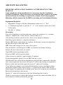
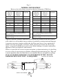
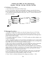
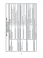
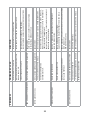
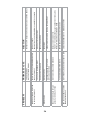
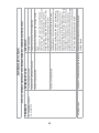
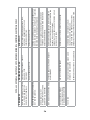
Built Better To Last Longer
Residential
Central Heat Recovery Ventilator
Product Specifications
and
Installation and User Manual
NuWave Series
Models
NW130, NW140, NW160, NW220, NW260
APPLICATION WARNING
It is always important to assess how the
operation of any Heat Recovery Ventilator
(HRV) may interact with vented combustion
equipment (i.e. gas furnaces, oil furnaces,
wood stoves, fireplaces. etc.)
Never install an HRV in a situation where
it’s normal operation, lack of operation, or
partial failure may result in the back drafting
on vented combustion equipment such as
water heaters, furnaces and fireplaces
DO NOT ATTEMPT INSTALLING THIS HRV WITHOUT
FIRST READING THIS ENTIRE MANUAL
ENERGY STAR RATED PRODUCTS: NW130, NW160
This product earned the ENERGY STAR
by meeting strict energy efficiency guidelines set by
Natural Resources Canada and the US EPA.
It meets ENERGY STAR requirements
only when used in Canada.
Summeraire Mfg.
Peterborough, Ontario,
Canada, K9J 6X6
Table of Contents
Model specifications . . . . . . . . . . . . . 3, 4, 5, 6, 7
Option Controls . . . . . . . . . . . . . . . . . . . 8, 9
Selecting a Location . . . . . . . . . . . . . . . . . . 10
Weather hood installation. . . . . . . . . . . . . . . .12
Dedicated Duct system . . . . . . . . . . . . . . . . 13
Indirect Duct system . . . . . . . . . . . . . . . . . 14
Direct Duct system . . . . . . . . . . . . . . . . . . 15
Fresh Air supply ducting . . . . . . . . . . . . . . . 16
Stale Air return system . . . . . . . . . . . . . . . . 17
Air Flow Balancing . . . . . . . . . . . . . . . . . . 19
Trouble shooting guide . . . . . . . . . . . . . . . . 22
Wiring Diagrams . . . . . . . . . . . . . . . . . . . 29
Replacement parts list . . . . . . . . . . . . . . . . . 30
Warranty . . . . . . . . . . . . . . . . . . . . . . . . 32
NOTE: Anytime the HRV is powered on allow 20 seconds for the
main control to reset prior to making any operational changes.
2
SPECIFICATIONS HEAT RECOVERY VENTILATORS PERFORMANCE RATINGS
MODEL: NW130
Options Installed:
None
Electrical:
120 V - 1.5 Amp
Exhaust Air Transfer Ratio:
0.02
Low Temp. Reduction Reduction During -25°C Test 20.0%
Maximum Unbalanced Airflow During -25°C Test: 8.5 L/s
Ext. Differential Pressure - Pascals
EXT. STATIC
PRESSURE
Pa
in. wg
25
0.1
50
0.2
75
0.3
100
0.4
125
0.5
150
0.6
175
0.7
200
0.8
225
0.9
VENTILATION PERFORMANCE
NET SUPPLY
GROSS AIR FLOW
AIR FLOW
SUPPLY
EXHUAST
L/S
CFM
L/S
CFM
L/S
CFM
67
143
70
149
70
149
62
132
65
137
64
136
56
118
58
123
59
125
49
104
51
108
54
113
43
91
45
95
47
100
38
80
40
84
41
86
34
72
35
75
33
71
30
63
31
66
26
57
25
52
25
54
22
47
12 1/2 IN
19 3/4 IN.
300
275
250
225
200
175
150
125
100
75
50
FRESH AIR
FROM
OUTSIDE
STALE AIR
FROM
HOUSE
STALE AIR
TO
OUTSIDE
FRESH AIR
TO
HOUSE
25
0
10 20 30 40 50 60 70
80 90
Gross Airflow - L/s
Net Supply
24 1/8 IN.
Net Exhaust
ENERGY PERFORMANCE
HEATING
SUPPLY
TEMPERATURE
°C
i
0
ii
0
iii
0
iv
v
-25
°F
32
32
32
NET
AIR FLOW
L/S CFM
33
70
45
96
55
117
-13
30
64
SUPPLY/
EXHAUST
FLOW RATIO
0.92
1.00
.99
AVERAGE
POWER
(WATTS)
60
94
94
SENSIBLE
RECOVERY
EFFICIENCY
65
61
60
APPARENT
SENSIBLE
EFFECTIVENESS
80
70
68
NET
MOISTURE
TRANSFER
0.07
0.01
-0.01
0.94
71
60
76
0.07
SUMMERAIRE MANUFACTURING
TRENT METALS (2012) LIMITED
PETERBOROUGH, ONTARIO K9J 6X6
Home Ventilating Institute
NW130-SP-EN-REV3
3
SPECIFICATIONS HEAT RECOVERY VENTILATORS PERFORMANCE RATINGS
MODEL: NW140
Electrical:
Exhaust Air Transfer Ratio:
Low Temp. Reduction Factor:
Low Temp. Imbalance Factor:
%XT$IFFERENTIAL0RESSURE0ASCALS
EXT. STATIC
PRESSURE
Pa
in. wg
25
0.1
50
0.2
75
0.3
100
0.4
125
0.5
150
0.6
175
0.7
200
0.8
225
0.9
250
1.0
120 V - 1.2 Amp
0.04 @ 0.4 in wg. (100 Pa)
17.8% Supply - 13.8% Exhaust
0.86
VENTILATION PERFORMANCE
NET SUPPLY
GROSS AIR FLOW
AIR FLOW
SUPPLY
EXHUAST
L/S
CFM
L/S
CFM
L/S
CFM
71
151
74
157
64
136
65
138
68
144
61
130
60
127
62
133
58
123
55
117
57
122
55
117
50
107
52
111
52
110
45
96
47
100
48
102
41
87
43
90
44
94
36
76
37
79
41
87
32
68
33
70
37
79
24
52
26
54
34
72
14 1/4 IN.
20 IN.
STALE AIR
FROM
HOUSE
FRESH AIR
FROM
OUTSIDE
FRESH AIR
TO
HOUSE
STALE AIR
TO
OUTSIDE
'ROSS!IRFLOW,3
28 1/4 IN.
#UBIC&EET0ER-INUTE#&-
Gross Supply
Gross Exhaust
ENERGY PERFORMANCE
HEATING
SUPPLY
TEMPERATURE
°C
i
0
ii
0
iii
0
iv
-25
°F
32
32
32
-13
NET
AIR FLOW
L/S CFM
30
63
46
98
55
118
32
69
SUPPLY/
EXHAUST
FLOW RATIO
1.03
1.00
1.00
.91
AVERAGE
POWER
(WATTS)
80
118
136
102
SENSIBLE
RECOVERY
EFFICIENCY
68
63
61
59
APPARENT
SENSIBLE
EFFECTIVENESS
82
74
71
82
NET
MOISTURE
TRANSFER
0.01
0.02
0.02
0.04
SUMMERAIRE MANUFACTURING
TRENT METALS (2012) LIMITED
PETERBOROUGH, ONTARIO K9J 6X6
Home Ventilating Institute
NW140-SP-EN-REV4
4
SPECIFICATIONS HEAT RECOVERY VENTILATORS PERFORMANCE RATINGS
MODEL: NW160
Options Installed:
Defrost Internal Dehumidistat
Electrical:
120 V - 1.27 Amp
Exhaust Air Transfer Ratio:
.02
Low Temp. Ventilation Reduction During -25°C Test: 20%
Maximum Unbalanced Airflow During -25°C Test: 7 L/s
EXT. STATIC
PRESSURE
Pa
in. wg
25
0.1
50
0.2
75
0.3
100
0.4
125
0.5
150
0.6
175
0.7
VENTILATION PERFORMANCE
NET SUPPLY
GROSS AIR FLOW
AIR FLOW
SUPPLY
EXHUAST
L/S
CFM
L/S
CFM
L/S
CFM
84
178
86
184
110
234
77
163
79
169
103
220
71
152
74
157
99
210
63
134
65
139
91
194
55
116
56
120
81
173
43
92
45
96
67
143
23
49
24
51
53
113
17 3/4 IN.
Ext. Differential Pressure - Pascals
(IN W.C. = PA ÷ 250)
20 3/4 IN.
200
175
150
125
100
75
50
Supply
Exhaust
25
20 40
60 80 100 120
Gross Airflow - L/s (CFM = L/s ÷ .47)
STALE AIR
FROM
HOUSE
FRESH AIR
FROM
OUTSIDE
FRESH AIR
TO
HOUSE
STALE AIR
TO
OUTSIDE
36 IN.
ENERGY PERFORMANCE
SUPPLY
TEMPERATURE
HEATING
°C
0
0
0
-25
COOLING
35
°F
32
32
32
-13
NET
AIR FLOW
L/S CFM
30
64
45
95
54
114
32
68
95
31
65
POWER
CONSUMED
(WATTS)
71
90
101
85
83
SENSIBLE
RECOVERY
EFFICIENCY
76
71
69
69
APPARENT
SENSIBLE
EFFECTIVENESS
86
80
77
88
LATENT RECOVERY
MOISTURE
TRANSFER
0.01
0.02
0.02
0.04
TOTAL RECOVERY EFFICIENCY
18
SUMMERAIRE MANUFACTURING
TRENT METALS (2012) LIMITED
PETERBOROUGH, ONTARIO K9J 6X6
Home Ventilating Institute
NW160-SP-EN-REV4
5
SPECIFICATIONS HEAT RECOVERY VENTILATORS PERFORMANCE RATINGS
MODEL: NW220
Options Installed:
Defrost Internal Dehumidistat
Electrical:
120 V - 1.3 Amp
Exhaust Air Transfer Ratio:
0.014
Low Temp. Ventilation Reduction During -25°C Test: 16%
Maximum Unbalanced Airflow During -25°C Test: 14 L/s
EXT. STATIC
PRESSURE
Pa
in. wg
25
0.1
50
0.2
75
0.3
100
0.4
125
0.5
150
0.6
175
0.7
VENTILATION PERFORMANCE
NET SUPPLY
GROSS AIR FLOW
AIR FLOW
SUPPLY
EXHUAST
L/S
CFM
L/S
CFM
L/S
CFM
110
234
112
237
105
223
106
226
108
229
100
214
102
217
103
220
95
203
98
209
100
212
88
187
92
197
94
200
82
175
86
183
87
185
74
157
79
169
81
171
61
129
17 3/4 IN.
Ext. Differential Pressure - Pascals
(IN W.C. = PA ÷ 250)
20 3/4 IN.
225
200
175
150
125
100
75
Supply
50
Exhaust
25
0
20
40
60
80
100
120
Gross Airflow - L/s (CFM = L/s ÷ .47)
STALE AIR
FROM
HOUSE
FRESH AIR
FROM
OUTSIDE
FRESH AIR
TO
HOUSE
STALE AIR
TO
OUTSIDE
36 IN.
ENERGY PERFORMANCE
SUPPLY
TEMPERATURE
HEATING
°C
0
0
0
-25
COOLING
35
°F
32
32
32
-13
NET
AIR FLOW
L/S CFM
40
84
66
140
86
182
34
72
95
42
89
POWER
CONSUMED
(WATTS)
103
132
158
116
104
SENSIBLE
RECOVERY
EFFICIENCY
68
62
58
61
APPARENT
SENSIBLE
EFFECTIVENESS
77
68
64
79
LATENT RECOVERY
MOISTURE
TRANSFER
0.01
0.00
0.00
0.03
TOTAL RECOVERY EFFICIENCY
29
SUMMERAIRE MANUFACTURING
TRENT METALS (2012) LIMITED
PETERBOROUGH, ONTARIO K9J 6X6
Home Ventilating Institute
NW220-SP-EN-REV4
6
SPECIFICATIONS HEAT RECOVERY VENTILATORS PERFORMANCE RATINGS
MODEL: NW260
Options Installed:
Defrost Internal Dehumidistat
Electrical:
120 V - 3.7 Amp
Exhaust Air Transfer Ratio:
0.05
Low Temp. Ventilation Reduction During -25°C Test: 16.9%
Maximum Unbalanced Airflow During -25°C Test: 15.6 L/s
EXT. STATIC
PRESSURE
Pa
in. wg
75
0.3
100
0.4
125
0.5
150
0.6
175
0.7
200
0.8
225
0.9
250
1.0
275
1.1
VENTILATION PERFORMANCE
NET SUPPLY
GROSS AIR FLOW
AIR FLOW
SUPPLY
EXHUAST
L/S
CFM
L/S
CFM
L/S
CFM
125
265
133
283
138
294
121
257
129
274
131
279
118
251
126
268
125
266
116
246
123
262
119
254
113
240
120
256
114
243
110
235
118
251
110
234
106
226
114
241
102
217
100
212
106
226
96
205
94
200
101
214
92
196
16 IN.
25 7/8 IN.
325
Ext. Differential Pressure - Pascals
(IN W.C. = PA ÷ 250)
300
275
250
225
200
175
150
125
100
75
Supply
Exhaust
STALE AIR
FROM
HOUSE
FRESH AIR
FROM
OUTSIDE
FRESH AIR
TO
HOUSE
STALE AIR
TO
OUTSIDE
50
80
90
100
110
120
130
140
150
Gross Airflow - L/s (CFM = L/s ÷ .47)
34 1/2 IN.
ENERGY PERFORMANCE
SUPPLY
TEMPERATURE
HEATING
°C
0
0
0
-25
°F
32
32
32
-13
NET
AIR FLOW
L/S CFM
46
97
67
141
100
213
41
88
POWER
CONSUMED
(WATTS)
176
222
400
213
SENSIBLE
RECOVERY
EFFICIENCY
69
70
64
66
APPARENT
SENSIBLE
EFFECTIVENESS
86
84
80
87
LATENT RECOVERY
MOISTURE
TRANSFER
0.01
0.01
0.01
0.03
SUMMERAIRE MANUFACTURING
TRENT METALS (2012) LIMITED
PETERBOROUGH, ONTARIO K9J 6X6
Home Ventilating Institute
NW260-SP-EN-REV4
7
HRV LED function indicators
Note: a flashing LED is an indication that an external
timer or dehumidistat has initiated a high speed
ventilation sequence.
OPTIONAL CONTROLS
Installation of a user-accessible control with your product
will improve comfort and may significantly reduce the
product’s energy use.
20 Minute Remote Timer Touch Pad
Model ECPBT
This 20-Minute Touch Pad MUST be connected to the
“CT” terminals on the HRV exterior. This control will not
function if connected to PBT connection points.
Install using 18/2-thermostat wire or telephone wire. No
electrical box is required. Maximum number of ECPBT
controls per HRV is six (6).
Maximum cumulative lead length is 2000 lineal feet.
Touch pads are typically installed where 20 minutes of
high speed ventilation may be desired.
Once activated by a momentary push of the SELECT
button on the Touch Pad, the HRV switches to high
speed ventilation and the Touch Pad LED will illuminate.
The HRV will reset to the previously selected mode of
operation once the 20 minutes have expired. To cancel the
selection, momentarily depress the SELECT button on the
20-minute Touch Pad. The selection can also be cancelled
at any other optional control by momentarily depressing
the SELECT button.
8
Should a dehumidistat be activated then the LED on this
20 minute timer will illuminate until the dehumidistat is
turned off or automatically resets.
NOTE: This control will not respond while a crank timer
or dehumidistat is operational.
OPTIONAL CONTROLS
Wall Mount Dehumidistat
Model - SRDEH
This control is typically installed in an area of the home
where humidity may require automatic monitoring. This
could be a central location (i.e. near furnace thermostat)
or in a specific room (i.e. kitchen, laundry etc.). When
wall mount dehumidistats are used, set the HRV internal
dehumidistat to OFF. Connect to HRV using 18/2
thermostat wire or telephone wire.
No electrical box is required.
NuWave Digital Control
Model - SHEPHERD
The SHEPHERD is a wall mount liquid crystal display
device.
This control provides the opportunity to select all
available operating features of the HRV.
Simply push the select button once to highlight the screen.
Continue to press the select button until the desired
fearture is highlighted.
The HRV will then assume the selected mode of
operation.
Install using 18/2 thermostat wire or telephone wire up to
two may be installed per HRV.
No electrical box is required.
Refer to wiring diagram in this manual.
9
Model NW160
Illustrated
Air In
Filtered
Air Out
Installation Options
Warm
Exhaust
Cold
Supply
Warm
Supply
Cold
Exhaust
Standard Ventilation
1. Selecting a location
Typically the HRV is located in the
mechanical room with close proximity
to an outside wall. Other installation
locations are acceptable provided that
the ambient air temperature does not
fall below freezing. This is to prevent
the condensate drain lines from freezing.
10
2. Mounting the HRV
Included with the HRV are four (4) laminated rubber hanging straps. These are
to be secured at each of the four corners of the HRV using the screws provided.
The other ends of the straps should be secured to the floor joists using large head
screws. To ensure proper condensate flow, HRV must be installed level in both
directions.
To ensure quiet operation of ENERGY STAR qualified HRV/ERV’s, each
product should be installed using sound attenuation techniques appropriate for
the installation.
3. Condensate Drain hose installation
Two (2) drain spigot assemblies are provided. These are to be installed through
the drain pan holes provided. Simply install the spigot through the openings
and secure in place by installing the nylon washer and nut on the outside of the
cabinet. Once installed, attach 1/2” plastic tubing (not supplied) to the spigots.
Create a trap by forming a loop in the tubing. This will prevent the cross
contamination of the air streams through the tubing. Ensure that the condensate
drain tubing is not exposed to freezing temperatures. Typically the drain line is
connected into a floor drain, sink or stand pipe.
Create Trap
11
4. Outside Weatherhoods and Ducting to the outside.
Inner Liner
Weatherhood
Collar
Insulation
Clamp
Vapour Barrier
The outside weather hoods must have built in bird screens to prevent birds and
rodents from entering the duct system. Minimum mesh size of 1/4” must be
used. Smaller mesh size will result in restricted air flows with increased potential
for the development of blockages.
Vent hoods with gravity dampers must not be used.
Weather hoods should be installed:
a)
b)
c)
d)
A minimum of 6 ft. apart from each other.
At least 18” above ground level
Away from sources of contaminates such as automobile exhaust
fumes, gas meters, garbage cans.
Locate away from prevailing winds whenever possible.
The size and design of the weather hoods shall be selected to ensure adequate
free area to minimize air flow restrictions.
It is recommended that 6” insulated ducting with a integral single piece vapour
barrier be provided. Due to the high air flow restrictions in insulated flex duct
it is recommended that run lengths be kept to a minimum, stretched tightly and
with as few elbows as possible, if length greater 25 ft. use 7” insulated duct.
Minimum RSI value of 0.75 (R4) is required.
Weather hood collar should be screwed to inner surface of sill plate and sealed
with high quality caulking or aluminum faced tape. Both the inner and outer
liners of flexible ducting should be securely attached to the weather hood
tubing and collar and to the HRV collar. A good bead of high quality caulking
(preferably acoustical sealant) should be used prior to clamping the liners. It is
very important to ensure that the fresh air intake line is well sealed and that the
vapour barrier is sealed.
12
5. Installation Methods
The way that your Heat/Energy-recovery ventilator is installed may make a
significant difference to the electrical energy that you will use. To minimize the
electricity use of the Heat/Energy-recovery ventilator, a stand-alone fully ducted
installation is recommended. If you choose a simplified installation that operates
your furnace airhandler for room-to-room ventilation, an electrically efficient
furnace that has an electronically commuted (EC) variable speed blower motor
will minimize your electrical energy consumption and operating cost.
Dedicated Duct System.
In this arrangement the HRV is installed with a dedicated duct system. All
applicable rooms are exhausted and provided with fresh supply air as required.
The main advantage of this type of installation is it provides the ability to
balance the exhaust and supply air streams from each serviced room.
The HRV system operates independent of the home’s heating system.
Please refer to fig I. below.
Stale Air
Exhaust
Fresh Air
Exhaust Air
Fresh
Air In
fig. I
13
Indirect Duct System
Safety Warning
Some Building Code and Combustion Appliance Installation Codes do not allow
location of return air grills or any opening such as a breather ‘T’ in an enclosed
room with spillage susceptible combustion appliances. If combustion appliances
are used, and not yet enclosed in a room, locate the grill or breathing ‘T’ outside
any future wall locations and a minimum distance of 6 feet from the combustion
appliance.
This method of installation permits localized exhaust of indoor air and uses the
existing forced air system to distribute fresh air.
Although independent room balancing of exhaust air can be achieved with the
indirect duct system, the distribution of fresh supply air cannot be balanced.
Where required by local codes, the HRV/ERV supply duct may be directly
connected to the furnace return air duct. The supply duct shall be positioned as
shown on the attached drawing. In this application no opening such as a breather
‘T’ is used.
Also, where permitted by local codes, the HRV/ERV supply duct may be
indirectly connected to the furnace return air duct using a breather ‘T’. In this
application, the breather ‘T’ is installed into the HRV/ERV supply duct before
the connection to the return air duct. Leaving a gap in the ventilation supply
duct in place of the breather ‘T’ is acceptable but not recommended. In this
installation, a grill is placed in the furnace return air duct and the HRV/ERV
supply duct is pointed at this grill at a minimum distance of 100mm (4”) but not
greater than 300mm (12”). The free area of the grill shall not be less than the
free area of the supply duct. Call backs have occurred because it was thought
that something had been accidently left out of the installation.
This method of installation requires that the forced air circulation fan be
operated when the HRV is in use.
Stale Air
Exhaust
Please refer to fig II. below.
Minimum 36"
Breathing "T"
Fresh Air
Supply
fig. II
Fresh
Air In
Stale
Air Out
14
Direct Duct System
Safety Warning
Some Building Code and Combustion Appliance Installation Codes do not allow
location of return air grills or any opening such as a breather ‘T’ in an enclosed
room with spillage susceptible combustion appliances. If combustion appliances
are used, and not yet enclosed in a room, locate the grill or breathing ‘T’ outside
any future wall locations and a minimum distance of 6 feet from the combustion
appliance.
This method of installation is used primarily when it is not reasonable to install
dedicated duct runs from the HRV to the various rooms of the dwelling. In this
installation the warm exhaust and warm supply duct runs from the HRV are
connected directly to the forced air heating system ductwork.
This method of installation does not permit source capture of the indoor air nor
does it permit room balancing.
Where required by local codes, the HRV/ERV supply duct may be directly
connected to the furnace return air duct. Where both the exhaust and the supply
duct are installed into the return air duct the exhaust air duct shall be positioned
upstream at a distance of not less than 1 meter (or 3 feet) from the supply duct.
The supply duct shall be positioned as shown on the attached drawing. In this
application no opening such as a breather ‘T’ is used.
Also, where permitted by local codes, the HRV/ERV supply duct may be
indirectly connected to the furnace return air duct using a breather ‘T’. In this
application, the breather ‘T’ is installed into the HRV/ERV supply duct before
the connection to the return air duct. Leaving a gap in the ventilation supply
duct in place of the breather ‘T’ is acceptable but not recommended. In this
installation, a grill is placed in the furnace return air duct and the HRV/ERV
supply duct is pointed at this
grill at a minimum distance
Stale Air
of 100mm (4”) but not greater
Exhaust
than 300mm (12”). The free
fig. III
area of the grill shall not
be less than the free area of
the supply duct. Call backs
Minimum 36"
have occurred because it was
thought that something had
Fresh Air
been accidently left out of the
Breathing "T"
Supply
installation.
The Direct Duct System
method of installation requires
that the forced air system
circulation fan be operated
when the HRV is in use.
Please refer to fig. III.
Fresh
Air In
15
Stale
Air Out
6. Interior Ducting
Ducting to the central forced air ductwork system, or if used, a dedicated duct
system, should be made of galvanized metal whenever possible.
To minimize airflow losses, runs should be kept as short as possible using 45
degree elbows instead of 90 degree. Whenever possible use “Y” fittings instead
of “T” fittings.
All joints must be fastened with screws, rivets or duct sealant and wrapped
with a quality duct tape to prevent leakage. If standard grills are used, it is
recommended that wall grills of not less than 6” x 12” and floor grills of no less
than 4” x 10” be used to minimize air flow restrictions.
7. Fresh Air Supply Ducting
Fresh air supply ducting to the living space may be either a dedicated or an
indirect duct system. Please refer to figures I and II.
Should the indirect method be used it is suggested that at the point of
connection to the HRV that a short length of flex duct be used to electrically
isolate the two systems.
Fresh air supply grills may be either wall or ceiling mounted. Avoid locating
these grills where room occupants may be exposed to the fresh air supply as this
air temperature may be slightly less than the room air temperature.
Also, it is recommended that adjustable grills such as round “Tech Grills” be
used to permit balancing of the ventilation by room application.
It is recommended that a breathing “T” be installed in the fresh air duct between
the HRV and the central distribution system. This will maximize efficiency, but
hard connection is acceptable.
16
8. Stale Air Return System
The stale air return system is used to extract humid, stale air from the areas
of the dwelling where the worst air quality conditions might exist. These may
include areas such as laundry rooms, bathrooms and kitchens. Note that C.S.A.
Standard F326 requires that air be exhausted from each room with a forced air
furnace.
Wall stud spaces can be used as ducting for high wall returns provided that they
are lined with galvanized metal.
Note: Check local code compliance before implementing.
Adjustable “Tech Grills” are recommended for use in the return air system. They
can be wall or ceiling mounted thereby permitting balancing of the air being
exhausted. Stale air return grills should be located at opposite ends in the room
to the fresh air grills to ensure good air exchange.
Please note that the exhaust air stream from a kitchen area must never be
connected to the kitchen range hood. Instead an exhaust grill should be mounted
high on the wall as required by local codes so as not to extract cooking by
products.
9. Air Flow Balancing
READ THE APPLICATION WARNING AT THE FRONT OF THIS MANUAL.
A magnehelic gauge and pilot tube flow measuring system is used for
easy and accurate air flow measurement
Upon completion of the installation it is necessary that the Ventilation System
be balanced. This is necessary to ensure that the volume of air being exhausted
from the dwelling is equal to the volume of air being supplied. Balancing will
also ensure that the HRV is operating at it’s maximum efficiency.
Detailed check list to be carried out prior to balancing.
a)
b)
c)
d)
e) Install air flow station in each of the warm air streams.
Ensure that all ductwork is secured and sealed.
Drain connections are in place and drain trap filled with water.
Dwelling vapour barrier is complete and intact.
Fireplace dampers, windows and doors are closed.
17
f) Clothes dryer off, (if vented to the outdoors)
g) Furnace, hot water heater, (non direct vent) are turned off.
h) All other exhaust fans are off.
i) Ensure that HRV filters and core are in place and integral balancing dampers
are wide open.
j) Power up HRV and set to high speed.
k) Adjust all branch tech grills and registers to desired air flows.
l) After taking readings at both the stale air being exhausted and the fresh
air supply air stream, damper down the higher air flow stream with the
integral balancing damper to equal the lower volume air stream.
m) Once the air flows are balanced lock the balancing dampers in place.
n) While it is necessary to ensure that both air streams are balanced within
10% of each other, a near balanced condition should be possible.
o) Upon completion, return the fan speed selection to the normal speed of low.
A positive pressure situation within the dwelling may drive moist air into
the external walls of the dwelling where, in cold weather, it may condensate,
potentially causing structural damage.
A negative pressure within the dwelling may have severe undesirable effects.
In some geographic locations, radon gas may be drawn into the living space.
A negative condition may also cause back drafting of vented combustion
appliances such as fireplaces and furnaces.
When it is possible for excessive pressurization or depressurization of a dwelling
to occur it may be necessary to perform a House Pressure Test. This test is most
important where fuel fired devices are installed that are susceptible to spillage.
IT IS YOUR RESPONSIBILITY TO DETERMINE IF THE “HOUSE
PRESSURE TEST” IS REQUIRED.
18
Air Flow Balancing
READ THE APPLICATION WARNING AT THE FRONT OF THIS
MANUAL.
Upon completion of the installation it is necessary that the Ventilation
System be balanced. This is necessary to ensure that the volume of air being
exhausted from the dwelling is equal to the volume of air being supplied.
Balancing will also ensure that the HRV is operating at it’s maximum efficiency.
Equipment Required:
•
•
•
Magnahelic Gauge or Inclined Manometer with scale to 1” WC
¼” diameter rigid tube to provide 2”, +/- 1/16” insertion into each of the
2 door ports
Flexible ¼” tubing
Procedure:
Turn off all appliances and fans that may vent to the outdoors (i.e. vacuums,
furnaces, range hoods, clothes dryers, water heaters etc.).
All dwelling windows and doors are closed, close fireplace dampers.
Dwelling vapour barrier is complete and intact.
Ensure HRV drain connections are in place, drain trap is created in drain hose
and that the trap is filled with water.
HRV filters and energy recover cores are in place.
Turn on furnace circulating fan if HRV is connected to furnace ducting.
Ensure all duct connections are sealed.
Open HRV balancing dampers fully.
Power up HRV and set speed to high.
Allow system to stabilize, approximately 2 minutes.
Position magnahelic gauge close to HRV and set to zero.
With flexible line connected to magnahelic and rigid tube connected to flexible
tube, insert rigid tube into lower door port 2” and record reading at magnahelic.
Remove tube and insert into upper door port 2” and record reading.
Close balancing damper associated with the higher reading until that reading
equals the required value shown in Fig. 5 to provide the same CFM. Secure
both dampers by tightening the locking screws once the set points are established.
Recheck both pressures and record.
Install 1/4” white hole plugs provided into balancing ports in door.
While it is necessary to ensure that both air streams are balanced within 10%, a
near balanced condition should be possible.
19
Fig. 5
MODEL NW130 ONLY
Refer to the following conversion chart to determine CFM flow.
Mag Reading
Inches WG
Supply Air
Stream
Mag Reading
Inches WG
Supply Air
Stream
CFM
Equivalent
Mag Reading
Inches WG
Exhaust Air
Stream
Mag Reading
Inches WG
Exhaust Air
Stream
CFM
Equivalent
0.29
0.28
0.31
.029
70
0.57
0.56
70
80
0.53
0.52
0.34
80
0.34
93
0.41
0.38
93
0.38
0.35
100
0.38
0.32
100
0.41
0.40
108
0.32
0.27
108
0.43
0.42
112
0.26
0.24
117
0.45
0.44
117
0.22
0.22
117
0.47
0.48
125
0.18
0.18
125
Note 1
Note 2
Note 1
Note 2
Note 1 - Dedicated Supply and Exhaust System,
NO furnace present
Note 1 - Dedicated Supply and Exhaust System,
NO furnace present
Note 2 - Furnace fan running on Heat Speed,
Return @ .10” ESP.
Note 2 - Furnace fan running on Heat Speed,
Return @ .10” ESP.
A positive pressure situation within the dwelling may drive moist air into the external
walls where, in cold weather it may condense, potentially causing structural damage.
A negative pressure situation within the dwelling may have severe undesirable
effects. In some geographic locations, radon gas may be drawn into the living
space. A negative condition may also cause back drafting of vented combustion
appliances such as fireplaces and furnaces.
When it is possible for excessive pressurization or depressurization of a dwelling
to occur it may be necessary to perform a House Depressurization Test. This test
is most important where fuel fired devices are installed that are susceptible to spillage.
IT IS YOUR RESPONSIBILITY TO DETERMINE IF THE “HOUSE
DEPRESSURIZATION TEST” IS REQUIRED.
EXHAUST AIR STREAM
Magnahelic
Cold Supply
Warm Exhaust
Cold Exhaust
Warm Supply
SUPPLY AIR STREAM
Magnahelic
20
Summeraire HRV Air Flow Balancing
Models: NW140, NW160, NW220, NW260
A. Preliminary Procedures:
1. Seal all the unit’s ductwork with foil tape.
2. Close all windows and doors and fireplace damper, turn off all exhaust
devices (range hoods, clothes dryer, bath fan, etc.), make sure all filters are clean.
3. Set build-in balancing dampers fully open. Tap 1/8” hole in ductwork for
pitot tube insertion.
B. Balancing Procedures:
1.Set HRV to high speed. Make sure that the furnace blower is ON if the
installation is in any way connected to the ductwork of the furnace. If not,
leave the furnace blower OFF. Adjust air flow in branch lines if using source
point exhaust and/or supply.
2. If outside temperature is below -3°C (26°F), make sure defrost light is not
on while balancing.
3. Place magnahelic gauge on a level surface and adjust it to zero. Insert pitot
tube into exhaust air ductwork with tip aligned with ductwork, pointing away
from HRV, into air flow. Record the reading on gauge.
4. Move kit to other air stream HRV, insert pilot tube into fresh air ductwork
with tip aligned with ductwork, pointing towards HRV , into air flow.
Record reading on gauge. Adjust fresh air balancing damper until reading is
approximately the same as in exhaust air ductwork. If the reading in the fresh
air ductwork is less than in the exhaust air, go back and adjust the exhaust
balancing damper to equal the fresh air flow.
5. Secure dampers in place with fastening screw. Duct tape over pitot tube
holes.Convert FPM reading on gauge to CFM with conversion chart and
record on balancing sticker and affix to HRV near label.
6. Note: Unit is considered balanced if readings are within +/- 10%.
21
22
HUMIDITY LEVEL TOO HIGH
HUMIDITY MAY HAVE TO BE ARTIFICIALLY ADDED,
i.e. HUMIDIFIER.
ADJUST TO LOWER FAN SPEED OR INTERMITTENT
LIFE STYLE OF OCCUPANTS.
VENTILATION RATE TOO HIGH
HRV UNDERSIZED.
BALANCE HRV
SET DEHUMIDISTAT TO A HIGHER SET POINT.
DEHUMIDISTAT CONTROL SET TO LOW.
HRV AIR FLOWS IMPROPERLY BALANCED
BALANCE HRV
REPLACE.
INSPECT CONNECTION BETWEEN MOTOR SHAFT AND DAMPER,
COUPLING MAY BE LOOSE.
DEFECTIVE DAMPER MOTOR.
HRV AIR FLOWS IMPROPERLY BALANCED.
IF DAMPER DOOR DOES NOT OPERATE DURING “START UP
SELF DIAGNOSTIC” BUT POWER LIGHTS ARE ON, BOARD MAY
REQUIRE REPLACEMENT.
FAILED MAIN CONTROL BOARD.
FRESH AIR DUCT FROZEN
OR VERY COLD
(DEFROST LIGHT COMES ON) .
HUMIDITY LEVEL TOO LOW
REPLACE.
BROKEN DAMPER BLADE ASSY.
DEFROST NOT WORKING.
ENSURE HRV IS ON CONTINUOUSLY.
INCREASE FAN SPEED. BALANCE SYSTEM.
IMPROPER VENTILATION RATE.
PERSISTENT CONDENSATION
ON WINDOWS
SOLUTION
ADJUST DEHUMIDISTAT(S) TO CORRECT RH READING (see
operation manual), ADJUST TO A LOWER SETTING.
CHECK OPERATION OF DEHUMIDISTAT, IF DEFECTIVE, REPLACE.
INSTALL A DEHUMIDISTAT IN LIVING AREA OF HOME.
PROBABLE CAUSE
IMPROPER ADJUSTMENT
OF DEHUMIDISTAT(S).
PROBLEM
HRV TROUBLE SHOOTING GUIDE
OPERATION GUIDE
23
AIR FLOWS ARE POOR
CLEAN AND REINSTALL
REMOVE OBSTRUCTIONS IN DUCT(S), HOODS AND GRILLS.
1/4” MESH ON OUTSIDE HOODS PLUGGED
IMPROPERLY SIZED DUCTING
BALANCE HRV.
CHECK ORIENTATION LABEL ON FRONT OF CORE AND POSITION
CORE CORRECTLY.
HRV MAY NOT BE LEVEL
HRV HEAT EXCHANGE CORE NOT
INSTALLED PROPERLY
FILTER/CORE PLUGGED UP
CHECK WATER DRAIN CONNECTIONS.
MAKE SURE WATER DRAINS PROPERLY FROM THE PAN(S)
DRAIN LINES OBSTRUCTED
HRV AIR FLOW IMPROPERLY BALANCED
ENSURE “O” RINGS ON DRAIN SPIGOT SEATS PROPERLY
LOOK FOR KINKS IN LINE.
IF SUPPLY AIR IS INSTALLED INTO RETURN AIR OF FURNACE,
FURNACE FAN NEEDS TO RUN CONSTANTLY TO DISTRIBUTE
VENTILATION AIR COMFORTABLY.
ENSURE THAT A BREATHER “T” IS INSTALLED IN SUPPLY DUCT.
PREHEATER MAY BE REQUIRED.
OUTDOOR TEMPERATURE
EXTREMELY COLD.
DRAIN PAN (S) PLUGGED
LOCATE GRILLS HIGH ON WALLS OR UNDER BASEBOARDS.
POOR LOCATION OF SUPPLY GRILLS.
WATER IN BOTTOM OF HRV
BALANCE HRV.
HRV AIR FLOWS IMPROPERLY BALANCED.
AVOID HANGING CLOTHES TO DRY INSIDE,
AVOID STORING WOOD INSIDE AND VENT DRYERS OUTSIDE.
LIFESTYLES OF OCCUPANTS
SUPPLY AIR FEELS COOL
COVER POOLS, HOT TUBS ETC. WHEN NOT IN USE.
BALANCE HRV
NOTE: FROST BUILD UP IS EXPECTED ON CORES PRIOR
TO INITIATING A DEFROST CYCLE.
SET DEHUMIDISTAT TO A LOWER SETTING.
HRV UNDERSIZED TO HANDLE HOT TUB,
INDOOR POOLS, ETC.
HRV AIR FLOWS IMPROPERLY BALANCED
SOLUTION
PROBABLE CAUSE
DEHUMIDISTAT SET TOO HIGH
HRV AND/OR DUCTS FROSTING UP
PROBLEM
24
HRV STATUS PANEL FLASHING
HIGH CONTINUOUSLY
FROST ON FRESH AIR INTAKE
& STALE AIR EXHAUST FLEX
WATER LEAKS
CONDENSATION OR ICE BUILD
UP IN INSULATED DUCT
PROBLEM
ADJUST DEHUMIDISTAT TO HIGHER SET POINT
REPAIR SEAL OF ALL CRACKS AND TEARS
VAPOUR BARRIER INCOMPLETE
HRV INTERNAL DEHUMIDISTAT SET TO LOW
INSTALL CORE CORRECTLY
“FRONT” OF CORE HAS INSTALLATION INSTRUCTION LABEL
INSTALL WITH LABEL FACING HRV DOOR
OPERATE HRV ON LOWER SPEED ie. INTERMITTENT
HRV CORE INSTALLED IN REVERSE
LEVEL HRV
REPLACE GASKETING
DOOR GASKET DAMAGED
EXCESSIVE WATER DUE TO NEW
WET CONSTRUCTION
WRONG APPLICATION OF HRV
UNUSUALLY HUMID AMBIENT
HRV NOT LEVEL
TAPE ALL JOINTS
ENSURE THAT VAPOUR BARRIER IS COMPLETELY SEALED
INSPECT FAN WHEELS TO ENSURE THEY ARE TURNING FREELY
UNDER SIZED HRV
MALFUNCTION WITH HRV
INCOMPLETE VAPOUR BARRIER AROUND
INSULATED DUCT
SOLUTION
PROBABLE CAUSE
25
CONTROL FUNCTION
RESTART HRV. THIS WILL RESET THE ELECTRONIC
CONTROL BOARD
POWER UP HRV, CLOSE DOOR SAFETY SWITCH, TURN
POWER SWITCH TO ON. PLACE ONE LEAD OF VOLT METER
ON KNOWN NEUTRAL AND THE OTHER ON TERMINALS
ON BACK OF SWITCH, ONE AT A TIME. VOLTAGE READING
SHOULD BE LINE VOLTAGE ON BOTH BLACK LEADS. IF
NOT, THEN REPLACE SWITCH. CONFIRM NEUTRAL AT
SWITCH LEAD WITH KNOW NEUTRAL DISCONNECT POWER
TO HRV. IDENTIFY KNOWN NEUTRAL, POSITION ONE LEAD
OF OHM METER ON KNOWN NEUTRAL AND OTHER AT
NEUTRAL LEAD AT REAR OF SWITCH. IF NO READING THEN
INVESTIGATE CONNECTION OF NEUTRAL LEAD WIRE. AND
OUTPUT. IF NO READING THEN REPLACE FILTER.
DEFECTIVE POWER SWITCH
POWER OFF – UNPLUGGED FROM POWER SOURCE
REMOVE MAIN ACCESS DOOR AND CONTROL COVER
PLATE.
APPLY POWER TO HRV AND CLOSE DOOR SWITCH AND
TEST THE TWO LEADS ON BACK OF SWITCH, ONE SHOULD
HAVE A READING. CLOSE DOOR SWITCH AND CHECK
OTHER LEAD WITH METER AND KNOWN NEUTRAL. IF NO
READING IS PRESENT THEN REPLACE SWITCH.
DEFECTIVE DOOR SWITCH
NOTHING WORKS
ENSURE THAT DOOR SWITCH IS OPERATING
DOOR SAFETY SWITCH NOT ENGAGED
NO POWER INDICATION AT
ON/OFF SWITCH
SOLUTION
CHECK FOR POWER
PROBABLE CAUSE
LACK OF POWER AT SUPPLY
PROBLEM
NOTE: ALL EXTERNAL MAINTENANCE TO BE PERFORMED BY A CERTIFIED ELECTRICIAN ONLY
26
REMOTE MOTOR ASSEMBLY AND TIGHTEN SCREW ON
MOTOR SHAFT. CHECK SUPPLY /EXHAUST WHEELS FOR
BALANCE. REPLACE IF NECESSARY.
ENSURE THAT FAN WHEELS ARE NOT RUBBING ON FAN
HOUSING INLET RING.
SUPPLY OR EXHAUST BLOWER WHEEL OUT
OF ADJUSTMENT
AIR DUCT SYSTEM TOO SHORT
CHECK FOR CORRECT WIRE GAUGE (18) OR
WIRING TO HRV OR SWITCH
HRV MAKES AN ANNOYING NOISE
NOISE LEVEL TOO HIGH AT
DISTRIBUTION REGISTERS
WHEN HRV ON HIGH SPEED
TOUCH PAD
IMPROPER CONNECTION TO 24V TERMINALS
DISCONNECT LEADS AT DEHUMIDISTAT AND SHORT
TOGETHER. IF HRV RESPONDS TO HIGH SPEED THEN
REPLACE DEHUMIDISTAT.
DEHUMIDISTAT (S) NOT
WORKING (INTERNAL AND/OR
REMOTE WALL MOUNTED)
CONFIRM WIRING TO WIRING DIAGRAM.
CHANGE TO CORRECT WIRE GAUGE.
CHECK TOUCH PAD FOR PROPER CONNECTIONS.
ENSURE THAT CORRECT SWITCHES ARE BEING USED.
REDESIGN DUCT SYSTEM OR INSTALL SILENCER.
UNPLUG 120V POWER SOURCE, APPLY 120V DIRECTLY TO
MOTOR, IF MOTOR DOES NOT RUN, REPLACE CAPACITOR,
IF MOTOR DOES NOT RUN, REPLACE MOTOR.
BLOWER MOTOR NOT OPERATING
BUT POWER LIGHT ON.
REPLACE DOOR SWITCH.
DOOR INTERLOCK SWITCH
DAMPER MOTOR NOT ACTUATING,
NO ACTION WHEN SHORTING
DEHUMIDISTAT TERMINALS
SOLUTION
RESET CIRCUIT BREAKER OR REPLACE FUSE,
OR YOU MAY BE REQUIRED TO CALL AN
CERTIFIED ELECTRICIAN.
PROBABLE CAUSE
CHECK ELECTRICAL PANEL - CIRCUIT
BREAKER – FUSE.
CHECK HRV
PROBLEM
NOTE: ALL EXTERNAL MAINTENANCE TO BE PERFORMED BY A CERTIFIED ELECTRICIAN ONLY
27
CONTROL BOARD CHANGED
UNIT DOES NOT SEEM TO RUN
PROPERTY
FAN SPEED DOESN’T SEEM TO
CHANGE AS SELECTIONS ARE
MADE ON SELECT BUTTON.
DAMPER MOTOR STAYS IN
DEFROST. DEFROST L.E.D NOT
ILLUMINATED.
LEAD.
PROBLEM
RESET DIP SWITCHES TO ORIGINAL SPECIFICATIONS.
DETERMINE IF IT’S CORRECT AND CONFIRM THAT VOLT
METER IS READING CORRECTLY. ALL VOLTAGES MUST BE
MEASURED WITH DUCT SYSTEM INSTALLED.
LOW SPEED 97 VOLTS
MEDIUM SPEED 105 VOLTS
HIGH SPEED 120 VOLTS
IF THE VOLTAGES ARE CORRECT THEN THE DUCT SYSTEM
STATIC IS TOO LOW.
INCORRECT VOLTAGE, MEASURE LINE VOLTAGE
& VOLTAGE TO MOTOR.
DIP SWITCHES NOT SET AS INSTRUCTED
ENSURE THAT MOTOR AMP DRAW DOES NOT EXCEED
NAMEPLATE RATING. INCREASED STATIC (I.E. DAMPERING)
MAY BE NECESSARY.
PICK COMMON COLOURED (2) DAMPER MOTOR LEADS.
PROBE 1 OF THESE LEADS WITH 1 LEAD FROM METER.
WITH THE OTHER METER LEAD PROBE 1 OF THE OTHER
SINGLE METER SHOULD READ 30V OR 27V. THE POSITION
OF THE DAMPER MOTOR DETERMINES THE VOLTAGE YOU
WILL READ (IT WILL BE ONE OR THE OTHER) IF THESE
READINGS ARE OBTAINED, CHANGE THE DAMPER MOTOR.
IF NO VOLTAGE PRESENT, OR VOLTAGES ARE THE SAME,
CHANGE THE CONTROL BOARD.
IMPROPER DUCT SYSTEM INSTALLED.
DEFECTIVE DAMPER MOTOR
DEFECTIVE CONTROL BOARD
SOLUTION
DISCONNECT LEADS AT BOTH ENDS @ TEST FOR
CONTINUITY BETWEEN LEADS.
PROBABLE CAUSE
EXTERNAL LOW VOLTAGE WIRE IS SHORTED
OUT BY A STAPLE OR NAIL
NOTE: ALL EXTERNAL MAINTENANCE TO BE PERFORMED BY A CERTIFIED ELECTRICIAN ONLY
28
LATCH MUST BE OPEN PRIOR TO LATCHING
DO NOT PULL DOOR SHUT
EXCESSIVE CLOSING FORCE
REPEATED FORCING OF LATCH
WEARS OFF LOCKING TAB ALLOWING IT TO POP
OPEN. FORCING DOOR SHUT, THEN FORCING
LATCH WEARS OFF LOCKING TAB ON LATCH.
LATCH OPENS
NOT ALL WALL SWITCH
CONTROL ILLUMINATE WHEN
ONE IS ACTIVATED
LOCKED ON HIGH SPEED
REPLACE LATCH
DEFECTIVE TEMPERATURE SENSOR
DEFROST CYCLE ACTIVE
DURING ABOVE FREEZING
OUTDOOR TEMPERATURE
SOLUTION
WHEN UNIT IS INITIALLY
POWERED ON, UNIT STAYS
IN DEFROST MODE LONGER THAN
10 MINUTES
REPLACE
SHOULD BE LESS THAN 2,000 LINEAL FEET IN TOTAL
DEFECTIVE CONTROL.
REPLACE
FEED LINE TO WALL SWITCH CONTROL
TOO LONG
REDUCE SET POINT
DEHUMIDISTAT SET TOO LOW
DEHUMIDISTAT DEFECTIVE
CHANGE SENSOR
CHANGE BOARD. WHEN CHANGING BOARD ALWAYS SET
DIP SWITCHES TO EXACT POSITION OF DEFECTIVE BOARD
BEING REPLACED.
PROBABLE CAUSE
DEFECTIVE MAIN CONTROL BOARD
PROBLEM
NOTE: ALL EXTERNAL MAINTENANCE TO BE PERFORMED BY A CERTIFIED ELECTRICIAN ONLY
29
Replacement parts listing
Models NW160, NW220
20
14
13
1
12
15
11
2
10
3
4
9
21
8
7
6
5
Replacement parts listing
Model NW140, NW260
20
1
13
15
11
3
16
17
19
6
18
30
NumberItem Part
Description
1
8.HINGEPL
Hinge Door
2
8.COUPLINGDMPR
Damper Motor Coupling
3
8.MTRDMPR24VR
Damper Motor
4
8.SEAL130
Damper Door Seal
5
8.CORENW160
Heat Recovery Core
6
8.LATCH3
Door Latch
7
8.DRAINKITSHRV
Spigot Assy
8
8.PAN130SHRV
Drain Pan
9
8.MTR1186
Fan Motor
10
8.CAP375V5MFCapacitor
11
8.BOARNW
Main control board
12
8.SWRCKR
On/ Off Switch
13
8.SWPADDLE
Door Safety Switch
14
8.FILT103414
Air Filter
15
8.SENS22
Temperature Sensor
16
8.SEAL240
Damper Door Seal
17
8.PAN115SHRV
Drain Pan
8.PAN240SSHRV
Drain Pan
8.PAN240LSHRV
Drain Pan
18
8.CORENW140
Heat Recovery Core
8.CORENW260
Heat Recovery Core
19
8.MTRE19
Impellar Motor
8.MTRG11A6
Impellar Motor
208.TRANS1 Transformer
21
8.FILT103412
Replacement Air Filter
8.FILT143414
Replacement Air Filter
Not On Diagram
8.PLUG14
1/4” Plug
8.CAP370V5MFCapacitor
8.CAP475V6MF
Capacitor
8.CAP475V18MFCapacitor
8.DRAINTEE12
Drain Tee
8.STRAP24
24” Strapping
8.SENS8
Temp Sensor
31
WARRANTY
HRV Unit
Summeraire Mfg. warrants the entire Heat Recovery Ventilator to the original purchaser should it
prove to be defective by reason of defective material and or faulty workmanship with in two (2)
years of the purchase date. Extended warranties are offered for the “Core” and “Electrical
components” as outlined below.
Core
Summeraire Mfg. warrants the “Core” of the Heat Recovery Ventilator to the original purchaser if
the core has become defective by reason of defective material and/or faulty workmanship. This
warranty applies to the original purchaser of the Heat Recovery Ventilator for as long as they own
the dwelling.
Electrical Components
Summeraire Mfg. warrants the “Electrical components” of the Heat Recovery Ventilator to the
original purchaser if any of the electrical components have become faulty by reason of defective
material and/or faulty workmanship. This warranty applies to the original purchaser of the Heat
Recovery Ventilator for a period of five (5) years from the date of purchase as long as they own
the dwelling.
GENERAL PROVISIONS
Summeraire Mfg. will supply a replacement HRV unit or component as prescribed in the forgoing
section, F.O.B. Peterborough, Ontario, Canada. Replacement units and/ or components are
warranted for the remainder of the original warranty period.
This warranty does not cover defects caused by: modifications, alteration, abuse to, or misuse of
the product or it’s operation in a manner contrary to the instructions included with the unit at the
time of shipment, or failure to perform maintenance as detailed in aforementioned instructions.
This warranty expressly supersedes all other warranties and obligations of Summeraire Mfg.. No
person has authority to alter or modify the terms of this warranty in any matter.
This warranty does not include any freight, labour, including diagnostic labour, or sales tax that
might be incurred by the purchaser if a unit and or parts require replacement.
Under no circumstances shall Summeraire Mfg. be liable to the purchaser or any other person(s)
for any consequential damages, whether arising out of breach of warranty, breach of contract,
negligence or otherwise.
Keep your warranty at work for you. Please complete and mail your warranty Registration Card
to Summeraire Mfg., 2040 Fisher Drive, Peterborough, Ontario, Canada, K9J 6X6 to register this
warranty.
Built Better To Last Longer
Summeraire Mfg.
Peterborough, Ontario
Canada, K9J 6X6
X-NuWave-INSMAN-EN-REV29
Specifications and illustrations subject to change
without notice and without incurring obligations.