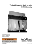
1
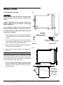
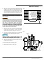
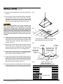
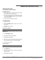
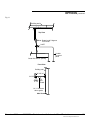
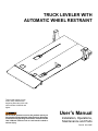
TRUCK LEVELER with
automatic wheel restraint
This manual applies to truck
leveler units manufactured
beginning December 2012 with
serial number 61065693 and
higher.
Do not install, operate or service this product unless you
have read and understand the Safety Practices, Warnings,
Installation and Operating Instructions contained in this
User’s Manual. Failure to do so could result in death or
serious injury.
User’s Manual
Installation, Operations,
Maintenance and Parts
Part No. 6011500E
table of contents
Introduction..................................................................2
Safety Signal Words....................................................2
Safety Practices..........................................................3
Installation ..................................................................4
Start-Up and Test.......................................................10
Operating Instructions...............................................12
Troubleshooting.........................................................16
Specifications............................................................20
Wiring........................................................................22
Planned Maintenance................................................24
Light/Alarms Status Table..........................................26
Hydraulic Manifold Block...........................................27
Hydraulic Schematic..................................................28
Parts List...................................................................29
Limited Warranty.......................................................39
Distributor Information...............................................40
introduction
Welcome and thank you for choosing this truck leveler.
This User’s Manual contains information that you need to safely install, operate and maintain the truck leveler. It
also contains a complete parts list and information about ordering replacement parts. Please keep and read this
User’s Manual before using your new light system.
safety signal words
You may find safety signal words such as DANGER, WARNING, CAUTION or NOTICE throughout this Owner’s
Manual. Their use is explained below:
This is the safety alert symbol. It is used
to alert you to potential personal injury
hazards. Obey all safety messages that
follow this symbol to avoid possible death or injury.
Indicates an imminently hazardous situation which,
if not avoided, will result in death or serious injury.
Indicates a potentially hazardous situation which, if
not avoided, could result in death or serious injury.
2
Indicates a potentially hazardous situation which, if
not avoided may result in minor or moderate injury.
Notice is used to address practices not related to
personal injury.
6011500E — Truck Leveler with Automatic Wheel Restraint
©2012 4Front Engineered Solutions, Inc.
December 2012
safety practices
Read these safety practices before installing, operating
or servicing the wheel restraint. Failure to follow these
safety practices could result in death or serious injury.
If you do not understand the instructions, ask your supervisor
to explain them to you or call your local distributor.
OPERATION
Use restricted to trained operators.
Use by untrained people can cause property damage, bodily
injury and/or death. Your supervisor should teach you the safe
and proper way to use the truck leveler. Read and follow the
complete OPERATION PROCEDURE on page 8 before use.
DO NOT USE THE TRUCK LEVELER IF IT IS NOT WORKING
RIGHT. Tell your supervisor it needs repair.
Keep hands and feet clear of the truck leveler at all times.
Stay clear of the truck leveler when it is moving.
Do not load or unload any vehicle unless you make certain the
wheel restraint has securely chocked the vehicle’s rear wheels
and set the brakes. If the wheel restraint does not chock the
vehicle’s tire for any reason, BE CERTAIN TO MANUALLY
CHOCK THE VEHICLE WHEELS BEFORE LOADING OR
UNLOADING.
Before chocking wheels or engaging vehicle restraint, dump
air from air ride suspensions and set parking brakes.
Before restraining a vehicle check that proper clearance is
available under the vehicle throughout the full range of chock
motion.
Do not operate the restraint with equipment, material, or people
directly in the path of the restraint.
INSTALLATION, MAINTENANCE AND SERVICE
Before doing maintenance or service push “STOP”
pushbutton in. Remove power at the fused disconnect
during all electrical or mechanical service. Disconnect must
be properly locked out during maintenance or service of
equipment. Failure to disconnect power may result in death
or serious injury.
Place barricades around pit on dock floor and drive while
installing, maintaining or repairing truck leveler.
Do not stand in the driveway between the dock and a backing
vehicle.
Do not use the truck leveler as a step.
Keep hands and feet clear of guide tracks and moving parts
at all times.
All electrical troubleshooting and repair must be done by a
qualified technician and meet all applicable codes.
Disconnect the power and properly tag or lock off before
doing any electrical work.
If it is necessary to make troubleshooting checks inside
the control panel with the power on, USE EXTREME
CAUTION! Do not place fingers or uninsulated tools
inside the control panel. Touching wires or other parts
inside the control panel could result in electrical shock,
death or serious injury.
If the wheel restraint does not operate properly using the
procedures in this manual, BE CERTAIN TO MANUALLY
CHOCK THE VEHICLE WHEELS BEFORE LOADING OR
UNLOADING. Call your local distributor for service.
Keep hands and feet clear of the chock mechanisms and guide
path at all times. Stay clear of the restraint when it is moving.
December 2012
6011500E — Truck Leveler with Automatic Wheel Restraint
©2012 4Front Engineered Solutions, Inc.
3
installation
PIT MOUNTED INSTALLATION
Before installation read and follow all safety practices
shown on page 3 and the operation section of the
manual.
Fig. 1
A
Improper installation of the truck leveler could result in
death or serious injury to dock workers or other users
of the truck leveler.
Place barricades around pit on dock floor and drive
while installing, maintaining or repairing truck leveler.
B
B
Be certain bystanders in the driveway stand clear when
truck leveler is operated.
3/8
3/8
1. Before installing truck leveler, use the certified pit drawings
to check the entire pit for correct dimensions and conduit
locations.
2. If your unit was shipped in one piece, grease hinge rod
and feed through hinge tubes on deck and rear hinge
angle. Insert roll pins through end hinge tubes.
Weld both
sides of flat
bars. Uphill
welds only.
No weld
on top
8" channel
(by others)
2
Support
bar
Section B-B
Detail A
3. Weld the four hinge angle support plates (supplied) to the
8" channel at front of pit. See Fig. 1.
4. Weld access cover support angles in hose junction of pit.
See Fig. 2.
Fig. 2
NOTE:
The following instructions cover the standard power supply
and controls supplied for the truck leveler with automatic
wheel restraint. If special controls, features or interlocks are
part of this installation, refer to the manuals or prints related
to those features for specific instructions.
5. Position the hydraulic power supply in the chosen location.
Be sure to orient the unit so that the side with the level
sight glass is clearly visible and the filler cap on top is
easily accessible.
A
A
Weld access
cover support
angle to pit curb
so that top of
cover is flush
with top of pit
Section A
4
6011500E — Truck Leveler with Automatic Wheel Restraint
©2012 4Front Engineered Solutions, Inc.
December 2012
installation, continued
6. Mount the outside communication lights/alarm and sign
so that they are visible to the vehicle driver. Refer to the
installation drawing for recommended dimensions. Make
sure the Red light is on top and the Green light is on the
bottom when the light assembly is mounted. See Fig. 3.
Fig. 3
Allow clearance for
seal and shelter
Suggested alarm
assembly location
NOTE:
The chock motion alarm assembly must be mounted in the
area of the chock.
RED/ GREEN
light assembly
Vehicle driver
caution sign
The chock motion alarm assembly must be mounted in
the area of the chock. Failure to mount the alarm in close
association with other dock and restraint components
may reduce its effectiveness which could result in
death or serious injury. The motion alarm assembly is
designed and controlled to sound whenever the chocks
are in motion. Each alarm is strictly associated with
a single unit, its mounting position must be such to
maintain that association at installation.
Approx. 90"
7. Mount the vehicle driver caution sign immediately below
the light and alarm assemblies. This sign must also be
clearly visible in the driver’s side mirror. See Fig. 3.
8. Disconnect the #6 hose linking the two lift cylinders and
feed through conduit running laterally across pit.
Fig. 4
Chock
Whenever running any hoses through conduit, the end
of the hose must be capped in order to prevent dirt and
other debris from entering the hydraulic system.
9. Mark hoses and feed through conduit from power unit
location to truck leveler pit.
10. Position power unit and anchor to floor.
11. Attach hoses to power unit. See Fig 4.
Release
December 2012
Truck leveler lift
6011500E — Truck Leveler with Automatic Wheel Restraint
©2012 4Front Engineered Solutions, Inc.
5
installation, continued
12. Remove cylinder shipping bolts from both cylinder base
brackets.
Fig. 5
13. Place a chain or other suitable lifting device through the
lugs located at the four corners of the deck. The lifting
lugs have been provided for the purpose of lifting during
installation. The truck leveler should not be lifted in any
other manner when placing into position. See Fig. 5.
Make sure lifting devices are in good condition and
have a lifting capacity of at least 15,000 lb. at the lifting
angle they are being used at. Stand clear of the truck
leveler when it is being placed into position. Never allow
anyone to stand on or near the truck leveler when it is
being lifted or placed into position. The truck leveler can
tip or swing into bystanders causing severe injury and/
or death.
14. Lift the entire unit into the pit. Square deck with pit sides,
shimming behind hinge angle where necessary. Hinge
angle should rest on top of support plates welded in step
2. Weld behind each stationary hinge segment to 8"
channel. See Fig. 6.
15. Manually extend each lifting cylinder until the base bracket
contacts the pit floor. Ensure lifting cylinder is plumb
when truck leveler is at level grade. Anchor cylinder base
brackets in position with 5/8" x 4-1/2" wedge anchors.
16. Attach chock and release hoses to corresponding marked
hoses on deck at pit hose junction. Attach #8 lift hose to
fitting at base of large lift cylinder. See Fig. 7.
17. Locate the limit switch in the cylinder housing. Run limit
switch wires down the cylinder housing and attach to
hydraulic hose. Feed hose and wires through conduit
(pit mounted units) to the other side of the truck leveler.
Attach #6 hose to lift cylinders. See Fig. 7.
18. Attach control panel to wall adjacent the dock opening on
the left side facing out from inside the dock at approximately
5' from the ground to center of control panel. See Fig. 8.
Fig. 6
5"
1"
5"
Weld base plate to rear channel behind every
base plate hinge tube using 1/4" welds
Fig. 7
3" rod
lift cylinder
4" rod
lift cylinder
#6 hydraulic hose
from top of 3" lift
cylinder to bottom
of 4" lift cylinder
Needle valve
#8 hydraulic
hose to truck
leveler lift
port
Conduit
Fig. 8
Mount control box on left
side of door opening.
Mounting hardware by others.
Eye level, approx. 60"
6
6011500E — Truck Leveler with Automatic Wheel Restraint
©2012 4Front Engineered Solutions, Inc.
December 2012
installation, continued
electrical installation
Before installation read and follow the Safety Practices
on page 3. Failure to follow these safety practices could
result in death or serious injury.
Before doing any electrical work, make certain the power
is disconnected and properly tagged or locked off. All
electrical work must be done by a qualified technician and
must meet all applicable codes. If it is necessary to make
troubleshooting checks inside the control panel with the
power on, USE EXTREME CAUTION. Do not place fingers
or uninsulated tools inside the control panel. Touching
wires or other parts inside the control panel may cause
electrical shock, death or serious injury.
High voltage power wires should be run in separate
conduit from low voltage control circuit wiring.
1. Wire the outside lights and alarm assembly to the control
panel according to the wiring diagram located inside control
panel.
2. Run limit switch wires back to the control panel. Wire the
limit switch wires to the control panel according to the wiring
diagram located inside control panel.
3. Wire the hydraulic power supply’s electrical box to the
control panel according to the wiring diagram located inside
control panel.
4. The Leveler Stored (terminals 24V and 10) and Door
Closed (terminals 24V and 9) signals are jumpered at the
factory. Their functions are to prevent the release of the
restraint while the leveler is not stored or the door is not
closed. Install input switch devices as necessary to use
these features. Reference drawing 6001045 for details.
5. Check the control panel for the voltage supplied. The
control panel is factory wired for the voltage specified on
the order. The label inside the control panel will show the
pre-wired voltage requirements.
December 2012
6011500E — Truck Leveler with Automatic Wheel Restraint
©2012 4Front Engineered Solutions, Inc.
7
installation, continued
NOTE:
A fused disconnect is required for each vehicle restraint as a
means of disconnecting and limiting incoming power to the
control panel. This disconnect is supplied by others unless
specifically ordered from 4Front Engineered Solutions, Inc.
For correct disconnect fuse size and fuse type, refer to the
charts and wiring diagram located inside control panel for the
proper voltage.
6. Check the drive motor for voltage requirements (it may
accept dual voltage). The drive motor’s voltage(s) are
stamped into the nameplate on the motor.
7. Verify that both steps 6 and 11 match the voltage specified
on the order. If they do not, contact your local representative
for assistance.
8. Check that the fused disconnect for this installation is
a lockable type and meets all applicable electrical and
safety codes.
9. Mount the fused disconnect near the control panel and
wire three phase power to it from an available power
source.
10. Check voltage at the disconnect. It must match voltages
checked in steps 6 and 11.
11. For vehicle presence sensor (optional) installed
termination, see schematic included in panel.
11.1 The sensor is a 4 wire device. First terminate the
positive lead (brown wire) to any "C" terminal on the
input board.
11.2 Terminate the negative lead (blue wire) to any "0V"
terminal in the panel.
11.3 Terminate the load lead (black wire) to the terminal
specified in the job specific wiring schematic.
11.4 Tape (insulate) the unused white wire.
12. Run three phase power wires from the fused disconnect
to the control panel.
12.1 Connect power to control panel.
12.2 Press RAISE.
12.3 If truck leveler raises, skip to step 14.
8
6011500E — Truck Leveler with Automatic Wheel Restraint
©2012 4Front Engineered Solutions, Inc.
December 2012
installation, continued
13. Reverse the motor rotation (if necessary) as follows:
13.1 Disconnect power.
13.2 Reverse the motor wiring by switching any two of the
three motor wires connected to the overload relay:
T1, T2, and T3.
13.3 Repeat 12.1-12.3.
14. Anchor outside guardrails with 3/8” x 3" wedge anchors
such that access is denied between the cylinder and dock.
See Fig. 15.
LIFT CYLINDER SYNCHRONIZATION
The two main lifting cylinders are synchronized before
they leave the factory. It should only be necessary to
re-synchronize them if the #6 hose connecting them is
disconnected allowing air to enter the line. This hose
should only be disconnected if it is required to run it through
conduit as in a pit mounted truck leveler installation.
PROCEDURE
1. Remove any load from the truck leveler
2. Remove the lift cylinder cover plates.
3. Open the needle valve on the larger cylinder (3" diameter
rod) by first loosening the Allen key set screw and then
turning the knurled knob counter-clockwise two turns.
4. Depress the RAISE pushbutton to raise the truck leveler
to its highest position.
5. Purge any air from the smaller “slave” cylinder (4" diameter
rod) by slowly loosening the bleeder screw at the top of
the cylinder housing until only oil escapes. Tighten the
bleeder screw.
6. Raise the truck leveler to its highest position. Close the
needle valve by turning clockwise until tight and then
tighten Allen key set screw.
7. Lower deck fully.
8. Replace the lift cylinder cover plates.
9. The truck leveler with wheel restraint is now ready for
start up and test. Close and secure the control panel.
December 2012
6011500E — Truck Leveler with Automatic Wheel Restraint
©2012 4Front Engineered Solutions, Inc.
9
restraint START-UP and test
Do not service this product unless you have read and
followed the Safety Practices, Warnings, and Operation
instructions contained in this manual. Failure to follow
these safety practices could result in death or serious
injury.
a) Verify proper operation of the valves for the RELEASE
function. While the motor is running, check for
magnetism at the solenoid coils. SV1 should be
energized. SV2 must NOT be energized. If solenoids
are not properly energized, refer to the troubleshooting
section of this manual to determine the cause of the
malfunction.
Before doing maintenance or service push “STOP”
pushbutton in. Remove power at the fused disconnect
during all electrical or mechanical service. Disconnect
must be properly locked out during maintenance or
service of equipment. Failure to disconnect power may
result in death or serious injury.
b) If SV1 is properly energized while SV2 is NOT
energized and the chock moves toward the chocked
position, swap hydraulic hoses at chock and release
ports and repeat step 2.2. Allow enough time while
holding the RELEASE pushbutton for the chock to
return to its stored position. See Fig. 4.
Before putting the restraint into service, there are
preparations and functional checks that must be made.
They are:
1) Bleeding air from the hydraulic cylinder and lines.
2) Checking chock travel.
c) If the chock is seated in the stored position and does
not move, monitor for a RELEASE pressure indication
at the PLC (input 3). If pressure is not indicated, refer
to the electrical troubleshooting section of this manual
to determine the cause of the pressure switch’s failure
to indicate pressure.
The following steps 2-4 will be taken with the power on
and the control panel open. Only qualified electrical
personnel should access the control panel while under
power.
1. Open the control panel and activate the system by turning
on the power at the fused disconnect.
2.Verify component hook-up:
2.1 Note the condition of the control panel’s indicator
lights. The RED light will likely be flashing upon initial
power up. This indicates a pre-operational condition.
If it is solid RED proceed to step 5.
2.2 Pull the STOP button out, then press and hold the
RELEASE pushbutton. The motor should run long
enough to bring RELEASE pressure up which will
reset the system and illuminate the panel’s RED light
solid. If successful, proceed to step 5.
2.3 If the chock is stored and the motor continues to run,
press the STOP button to stop the motor and perform
the following checks:
3. This mode provides a means to assign a unique time
stamp to each restraint assembly. The Calibration routine
will send the chock to the far end of its travel to determine
the time required to travel the whole of the unit’s length.
This value is then adjusted and used to maximize cylinder
stroke while preventing potential false hitches. Accurate
calibration requires there be no truck present at the dock
location being calibrated and the chock travel area should
be clear of obstruction and/or debris. In order to obtain an
accurate calibration, the chock must be monitored during
travel for binding or stalling. The most effective means to
affect this is to view the system pressure gauge located
on the power unit housing. Another method is to listen to
the pitch of the motor while the chock is in motion. Abrupt
changes in pressure or motor pitch imply restriction which
can adversely affect the accuracy of the calibrated value.
3.1To activate Calibration mode: insure the restraint is
stored (home position) with a solid red lamp illuminated
and the Stop button is pulled out. Simultaneously
press and hold the Engage and Release pushbuttons
for 5 seconds. Panel lamps will begin to flicker to
indicate the activation of the Calibration mode. If the
procedure completes successfully, the chock will
automatically reverse and return to the home position.
3.2To immediately halt Calibration mode: press the Stop
button. The restraint can then be returned to the home
position by normal means. If the calibration procedure
is interrupted in this manner, Calibration registers will
be cleared. No new values will be calculated.
10 6011500E — Truck Leveler with Automatic Wheel Restraint
©2012 4Front Engineered Solutions, Inc.
December 2012
restraint START-UP and test, continued
4.Verify CHOCK and RELEASE functions:
4.1 With the chock stored and the inside RED light
illuminated solid, ensure the STOP button is out and
press the CHOCK pushbutton. The chock should
move toward the chocked position and the inside
and outside RED lights will flash. The motion alarm
should sound while the motor is running. If the chock
fails to move, press the STOP button and refer to the
troubleshooting section.
4.2 The chocks will travel full stroke in approximately 45
seconds and should issue a Truck Not Found alert
indicated by the RED and AMBER lights flashing
together with an audible alarm pulse sound.
a) If a fault is issued indicated by a solid RED light
accompanied by the AMBER light flashing a count,
the chock may be traveling too slowly. Refer to the
troubleshooting section if this occurs.
b) If the motor stops and the inside GREEN light is
illuminated solid, the Full Stroke proximity switch
is misadjusted or malfunctioning. Refer to the
troubleshooting section for adjustment procedures if
this occurs.
4.3 With the chocks in the chocked position (chock’s full
travel), ensure the STOP button is out and press the
RELEASE pushbutton. Both chocks should move
toward the stored position and store. The time required
to store the chocks should not be greater than 45
seconds. Once both are stored, the motor will stop, the
inside RED light will illuminate solid and the outside
GREEN light will flash. Refer to the troubleshooting
section if errors occur.
5. Check the outside lights. With the chock retracted, the
green light should be flashing and the red light should
not be illuminated.
6. Check the override function:
6.1 Press the Chock pushbutton on the face of the
control panel. The inside red light will flash. The
outside lights should switch immediately to flashing
red. The chock will travel full stroke toward the
dock. A motion alarm should be sounding to indicate
motion.
6.3. When the Chock stops after approximately 45
seconds the fault alarm should sound. The RED
and AMBER lights will flash to indicate a Truck
Not Found condition. The outside Red light should
remain flashing.
6.4 Note PLC input 1 is OFF.
6.5 Select RESTRAINT override. The fault alarm should
silence and the inside lights should change to steady
Amber and Green. The outside lights should remain
flashing Red.
7. Check the Release function:
NOTE:
RELEASE will not function unless the truck leveler is in its
fully lowered position.
7.1 Press the Release pushbutton on the face of
the control panel. The inside lights should change
to Red flashing. The Red/Green outside lights
should remain Red flashing.
7.2. The chocks should travel full stroke and both store
themselves in its pocket. This travel should take
less than 45 seconds.
7.3. When the chocks stop in the pocket, the motor will
shut off and the inside and outside lights should
change back to steady Red inside and flashing
Green outside.
7.4 Note PLC input 1 is ON.
8. Check the chock function:
8.1 Press the CHOCK pushbutton on the face of
the control panel and let the chocks travel for 20
seconds. Press the STOP button. Pull STOP button
out and press the CHOCK pushbutton. The chocks
should run until the motor stops. The inside light
should change to steady green and the outside light
should stay flashing red.
8.2 Press the RELEASE pushbutton to restore the
chocks.
6.2. The chock should stop after approximately 45
seconds.
December 2012
6011500E — Truck Leveler with Automatic Wheel Restraint
©2012 4Front Engineered Solutions, Inc.
11
Operating instructions
Before operating the vehicle restraining device, read and
follow the Safety Practices, Warnings, and Operation
instructions contained in this manual. Use by untrained
people could result in death or serious injury.
Do not use the Restraint if it looks broken or does not
seem to work right. Tell your supervisor at once.
Keep hands and feet clear at all times. Stay clear of the
wheel restraint when it is moving.
Do not load or unload any vehicle unless you make
certain the wheel restraint has securely hitched the
vehicle’s rear impact guard and set the brakes. If the
wheel restraint does not chock the vehicle’s tire for
any reason, BE CERTAIN TO MANUALLY CHOCK THE
vehicle WHEELS BEFORE LOADING OR UNLOADING.
Enter the vehicle only when the GREEN signal light on
the control panel is on. You must check the GREEN
signal light each time that the vehicle is entered. If
the GREEN light goes off at any time during loading
operations, immediately cease loading operations and
check the wheel restraint to insure that it is securely
hitched.
If the power to the wheel restraint is interrupted,
immediately cease operations and check the unit.
consult the troubleshooting instructions to reset the
lights when power resumes.
Vehicles leaving or moving when loading and unloading
are in process, could result in death or serious injury.
Failure to follow these safety practices may result in
death or serious injury.
Vehicles should always enter and leave when the truck
leveler is in the fully lowered position only.
NOTE:
The following failure conditions will immediately halt motor
operation. A restraint fault will be issued.
• PS1 and PS2 on at the same time.
• Vehicle not found.
• Maximum motor run time – 45 sec.
• Early chock – 2.5 sec.
If vehicle restraint malfunctions, SOLID RED and FLASHING
AMBER lights indicate an error condition exists. An audible
alarm will sound when the maximum motor run time is
12 exceeded. Press RELEASE pushbutton to store restraint,
then CHOCK pushbutton if required. If restraint continues
to malfunction, manually chock wheels and switch to
RESTRAINT OVERRIDE. A qualified technician must service
the restraint.
For a description of the status of lights and alarms during
different operating conditions see page 26.
The wheel restraint requires that vehicles have adequate
under carriage clearance throughout the path of the
chock. Be sure 14" of clearance is present along the
entire path the chock will travel. Failure to do so may
result in damage to the vehicle, its attachments, or the
chock.
NOTE:
At all times that the chock is in motion the motion alarm will
sound.
to chock vehicle
1. Check for clearance under the vehicle throughout the
entire chock path.
2. Press Chock pushbutton.
NOTE:
Chock will not activate unless truck leveler is in fully lowered
position.
3. Inside light will switch from steady Red to flashing Red.
4. Outside lights will switch to flashing red.
5. When vehicle is properly chocked, the RED flashing inside
light will switch to a green steady light. Outside light will
remain flashing red.
If vehicle cannot be chocked, inside red and amber
lights will flash and the fault alarm will sound. If this occurs:
5.1Make certain vehicle brakes are set.
5.2Manually chock vehicle tires.
5.3Select RESTRAINT OVERRIDE.
5.4Inside lights will switch to steady Amber and Green,
and the fault alarm will silence.
5.5Outside lights will remain flashing Red.
6011500E — Truck Leveler with Automatic Wheel Restraint
©2012 4Front Engineered Solutions, Inc.
December 2012
Operating instructions, continued
OPERATING INSTRUCTIONS
(FOR STANDARD CONTROL PANELS)
TO RAISE vehicle :
1. Before raising vehicle, it MUST be properly restrained
with a suitable vehicle restraint system.
2. Once vehicle is safely chocked, it may be raised by pressing
and holding the RAISE pushbutton until the vehicle bed
is at the desired height.
3. Vehicle may now be loaded or unloaded.
TO LOWER vehicle :
1. Store dock leveler.
2. Press the lower pushbutton until the Truck Leveler is
fully lowered.
3. RELEASE vehicle restraint.
to release vehicle
NOTE:
RELEASE will not function unless the leveler is in its fully
lowered position.
1. Press Release pushbutton.
2. Inside light will switch to flashing Red.
3. Outside light will flash Red.
4. After Chock is stored, inside lights will switch to steady
red. Outside lights will switch to flashing green.
5. Vehicle may now pull out.
to stop chock
NOTE:
Chock travel may be stopped at any time during its travel.
1. Press Stop button.
2. Inside Red light will flash at a slow rate to indicate a
stopped condition.
3. Outside Red light will flash.
December 2012
6011500E — Truck Leveler with Automatic Wheel Restraint
©2012 4Front Engineered Solutions, Inc.
13
Operating instructions, continued
to restart chock
1. Pull Stop button out.
2. Inside and outside lights will remain unchanged. (Inside
light remains flashing Red, Outside light remains flashing
Red.)
3. Press either chock or release pushbutton. If the
chock pushbutton is pressed the chock will resume its
previous sequence. See previous section for details.
4. If the release pushbutton is pressed the Chock will
store itself in the same manner as it does when releasing
a vehicle.
5. After chock is stored, inside lights will switch to steady
red. Outside lights will switch to flashing green.
Jog
This feature will allow the restraint to be manually returned
to the stored position using the RESTRAINT OVERRIDE
switch and Release pushbutton in the event of certain
restraint failures. To initiate the Jog Mode, rotate and
hold the RESTRAINT OVERRIDE switch and press the
Release pushbutton to retract the wheel chock. See the
Panel Communications table for details regarding panel
lamp status.
to manually release chock
NOTE:
In the event of a power failure the chock may be manually
released to allow a vehicle to leave the dock.
1. Push STOP button in. Remove power at fused disconnect.
14 6011500E — Truck Leveler with Automatic Wheel Restraint
©2012 4Front Engineered Solutions, Inc.
December 2012
Operating instructions, continued
2. Identify the manual release valve located on the top of
the valve block of the power unit. See Fig. 9.
Fig. 9
3. The manual release valve is activated by adjusting the
valve fully counter-clockwise.
Manual release
Stay clear of the chock while it is being returned to the
stored position. Failure to do so may result in death or
serious injury.
4. Slide the chock back along the track until it is in the stored
position by slowly pulling the vehicle forward.
5. Adjust the valve fully clockwise and reapply power at the
fused disconnect after chock is in pocket.
to restart chock after manual release
1. Turn on power at fused disconnect.
2. Pull STOP button out.
3. Press release pushbutton.
4. The wheel restraint is now ready for use.
December 2012
6011500E — Truck Leveler with Automatic Wheel Restraint
©2012 4Front Engineered Solutions, Inc.
15
troubleshooting
Before doing maintenance or service push “STOP”
pushbutton in. Remove power at the fused disconnect
during all electrical or mechanical service. Disconnect
must be properly locked out during maintenance or
service of equipment. Failure to disconnect power may
result in death or serious injury.
Before doing any maintenance or repair read and follow
the safety practices listed on page 3 and the operations
section of this manual.
Place barricades on the dock floor around the truck
leveler and in the driveway in front of the equipment
while installing, maintaining or repairing the truck leveler.
NOTE:
This troubleshooting section assumes that the truck leveler
has been installed properly and that all electrical and hydraulic
connections have been made correctly. If this is a new
installation or electrical or hydraulic work has been done on
the unit, refer to the appropriate schematics and/or instructions
to verify that the unit is installed correctly.
RAMP WILL NOT LIFT (when RAISE
pushbutton is pressed)
1. MOTOR RUNS
1.1 Too much weight on ramp.
1.2 Ramp already at maximum height.
1.3 Pressure relief valve set too low - factory set at 2800
PSI.
1.4 Leaking or broken hose connection.
1.5 Failed pump or pump/motor coupling.
2. MOTOR DOES NOT RUN
2.1 Overload has been tripped.
2.2 Other electrical problem - consult appropriate
schematic.
16 6011500E — Truck Leveler with Automatic Wheel Restraint
©2012 4Front Engineered Solutions, Inc.
December 2012
troubleshooting, continued
3. RAMP WILL NOT LOWER
(when LOWER pushbutton is pressed)
3.1 Ramp is already in the fully lowered position.
Fig. 10
Roller should contact top
of cylinder gland
3.2 Defective lowering solenoid valve or coil. Replace.
3.3 Obstruction underneath ramp preventing downward
travel. Remove obstruction.
3.4 Velocity fuse(s) in lift cylinders tripped. Reset velocity
fuses by pressing raise pushbutton to lift ramp
slightly.
3.5 Other electrical problem - consult appropriate
schematic.
4. RAMP RAISES UNEVENLY
4.1 Lift cylinders not synchronized. Follow synchronizing
procedure described on page 9.
4.2 Leak or break in #6 hose connecting the two lifting
cylinders. Repair or replace.
5. CHOCK DOES NOT ENGAGE OR RELEASE
5.1 Ramp is not fully lowered. Lower ramp fully.
5.2 Limit switch is out of adjustment.
5.3 Remove cylinder enclosure cover exposing chock
cylinder with limit switch. See Fig. 16.
5.4 Lower truck leveler fully and then raise approximately
1".
5.5 Loosen nut on arm and adjust roller position such that
limit switch will trip just prior to truck leveler being fully
lowered.
5.6 Tighten nut on arm and lower truck leveler to check
that switch trips upon fully lowering unit. Several trials
may be necessary to get the adjustment correct.
5.7 Replace cylinder enclosure cover.
December 2012
6011500E — Truck Leveler with Automatic Wheel Restraint
©2012 4Front Engineered Solutions, Inc.
17
TROUBLESHOOTING
MECHANICAL TROUBLESHOOTING
1. Chock begins to move, drops back into pocket.
1.1Check chock for obstructions preventing proper
operation. Clear any obstructions present.
1.2Press the release pushbutton to reset chock.
1.3Check the rollers under the chock to ensure they
move freely. Lubricate as required.
1.4Lubricate the ramp surface of the chock pocket with
anti-seize compound.
1.5Press the chock pushbutton to chock vehicle.
2. Motor continues to run after vehicle is chocked.
2.1The motor will automatically shut off and an alarm
will sound.
2.2Select restraint override to silence the alarm.
2.3The hydraulic system is not making proper pressure,
check all hydraulic connections for leaks. Check all
electrical connections.
2.4Repair any leaks. Test operation of the vehicle restraint.
3. During release cycle motor continues to run after chock
is stored.
3.1The motor will automatically shut off and an alarm
will sound.
3.2Check all electrical and hydraulic connections and
components carefully.
NOTE:
For a table describing the status of the lights and alarms during
the operation of the wheel restraint see page 26.
18 6011500E — Truck Leveler with Automatic Wheel Restraint
©2012 4Front Engineered Solutions, Inc.
December 2012
TROUBLESHOOTING, continued
electrical TROUBLESHOOTING
Trouble Code Definitions
Trouble Trouble
Code Definition
Before doing maintenance or service push “STOP”
pushbutton in. Remove power at the fused disconnect
during all electrical or mechanical service. Disconnect
must be properly locked out during maintenance or
service of equipment. Failure to disconnect power may
result in death or serious injury.
2
PS1 and PS2 on at the same time
5
Motor run timeout exceeded
6
Chock pressure sensed too early
1. None of the lights on the controller in the control panel
are on.
1.1Check that the fused disconnect switch is on.
1.2Check all transformers and fuses. See wiring diagrams
located inside control panel.
Diagnostics
The PLC continuously monitors system operation and will
indicate when it is malfunctioning. If an error occurs that could
be potentially dangerous, the restraint will halt operation and
the inside panel lamps will display an indication of the error.
If a restraint fault has occurred:
• Inside Red lamp is on.
• Inside Amber lamp is flashing a trouble code.
• The unit will attempt to return to the stored position when
the Release pushbutton is pressed. All other functionality
is suppressed.
2. An indicator light on an outside light or on the control
panel does not work.
2.1Check for power across LED wires.
2.2If no power is present, check all wires, fuses, and
transformers leading to the lights.
2.3If power is present and light does not light replace
the LED.
3. The system’s controls operate properly, but the motor
does not operate.
3.1Check the overload relay.
3.2The overload is factory preset to automatically reset
after it cools in the event of an over-current condition.
If the overload relay has tripped, it will be indicated.
3.3Wait 1-2 minutes for the overload device to cool and
normal operations will be restored.
To identify the specific problem, count the flashes of the
Amber lamp and compare the number to the table below.
The count sequence will be repeated until the cause of the
restraint fault is corrected. A two second pause between
flash sequences is employed.
December 2012
6011500E — Truck Leveler with Automatic Wheel Restraint
©2012 4Front Engineered Solutions, Inc.
19
specifications
General
Platform size
tl-ac 1018: 120" wide x 216" long
tl-ac 1020: 120" wide x 240" long
Lifting capacity
60000 lb.
Vertical Travel
24" Standard
chock engagement distance
TL-AC 1018: 144" and 91"
TL-AC 1020: 91"
Platform weight
24" Travel:
TL-AC 1018 surface mount: 10,900 Lbs.
TL-AC 1018 pit mount: 10,000 lbs
TL-AC 1020 surface mount: 11,350 Lbs.
TL-AC 1020 pit mount: 10,450 lbs
Power unit
Pump
5.4 GPM @ 1800 rpm (gear pump)
Motor
7.5 hp, 3 ph, 1725 rpm, tefc, continuous duty
Approx. full load amperage:
208V/3PH/21A
230V/3PH/19A
460V/3PH/9.5A
575V/3PH/7.9A
Pressure relief setting
2800 psi
pressure switch settings
Chock 1400 PSI
Release 1300 PSI
Flow control
Fixed- 7 gpm
Reservoir capacity
16 gallon
20 6011500E — Truck Leveler with Automatic Wheel Restraint
©2012 4Front Engineered Solutions, Inc.
December 2012
specifications, continued
Acceptable Fluids: An all weather hydraulic fluid with a
viscosity of 15 CSt at 40°C (100°F), such as:
Shell Tellus T 15
Mobil Aero HFA (49011)
Exxon Univis: HV13, N15, J13
Texaco Aircraft Oil #1554
U.S. Oil Co.,Inc #ZFI-5606 (Low Temp.)
Control panel
Wiring schematic
Located inside control panel
minimum runtime setting
3 seconds
maximum runtime setting
TL-AC (5.4 GPM pump) 45 seconds
Secondary control voltage
24 vac
Cylinders
Lift fully synchronized
LIFT
24" Travel (standard)
1 - 5" Diameter piston, 3" diameter rod, 31-3/4" collapsed
length, 21-5/8" stroke
1 - 4" Diameter ram, 31-3/4" collapsed length, 21-5/8" stroke
chock
TL-AC 1018
(1) 3" diameter piston, 2" diameter rod, 91" stroke
(1) 3" diameter piston, 1-1/2" diameter rod, 67-1/2" stroke
TL-AC 1020
(2) 3" diameter piston, 2" diameter rod, 91" stroke
December 2012
6011500E — Truck Leveler with Automatic Wheel Restraint
©2012 4Front Engineered Solutions, Inc.
21
options
Before doing any electrical work, make certain the power
is disconnected and properly tagged or locked off. All
electrical work must be done by a qualified technician
and must meet all applicable codes. If it is necessary
to make trouble shooting checks inside the control
panel with the power on, USE EXTREME CAUTION. Do
not place fingers or uninsulated tools inside the control
panel. Touching wires or other parts inside the control
panel may cause electrical shock, death or serious
injury.
Do not service this product unless you have read and
followed the Safety Practices, Warnings, and Operation
instructions contained in this manual. Failure to follow
these safety practices could result in death or serious
injury.
wiring of control and pump options
auxiliary output
The wheel restraint control is provided with a normally
open contact point which closes when the trailer has been
chocked. This contact may be used for auxiliary equipment
or communication. Terminals R13 and R14 are the access
points for this feature. If power is lost while unit is chocked,
the connection between R13 and R14 will be lost.
Trailer Present sensor (Optional)
The trailer present sensor senses a vehicle at the dock and
transmits a signal to the control panel. This turns on the panel
face AMBER light. Mount the sensor. See Fig. 11. Ensure the
sensor's logic switch is set to L/O (Light Operate). The switch
is located on the top of the sensor under a plastic cover. Wire
the switch. Wire the sensor into the panel per the per the
job specific schematic located in the panel. Test for proper
operation as per below.
OPERATIONS
No Trailer Present
• Inside lights display Solid RED outside display GREEN.
Trailer Arrives
• Inside lights switch to Solid AMBER and RED, outside
lights continue to display GREEN.
Operator engages vehicle restraint
• Inside lights switch to Solid GREEN, outside lights switch
to display RED.
Operator releases vehicle restraint
• Inside lights switch to Solid AMBER and RED, outside
lights continue to display GREEN.
Trailer Departs
• Inside lights display Solid RED outside display GREEN.
\
NOTE:
See wiring diagrams located inside control panel.
22 6011500E — Truck Leveler with Automatic Wheel Restraint
©2012 4Front Engineered Solutions, Inc.
December 2012
options, continued
Fig. 11
Building wall
Top View
Note: Rotate head 5 degrees
from center
3-4477
Center line of door opening
Conduit
to control
panel
Front View
Building wall
34"- 48" ref.
315-370
C
E
1/2"
rigid
conduit
14' - 6' minimum
above grade
Side View
December 2012
6011500E — Truck Leveler with Automatic Wheel Restraint
©2012 4Front Engineered Solutions, Inc.
23
planned maintenance
2. Check for cuts in hoses and loose or leaking fittings.
Before doing maintenance or service push “STOP”
pushbutton in. Remove power at the fused disconnect
during all electrical or mechanical service. Disconnect
must be properly locked out during maintenance or
service of equipment. Failure to disconnect power may
result in death or serious injury.
Before servicing the truck leveler, read and follow the
Safety Practices on page 3 and the operation section of
this manual.
After checking lights, be certain lights are returned to the
proper display. If no vehicle is at the dock, or the vehicle
is not chocked, the RED inside light should be lit and
GREEN outside light should be flashing. If a vehicle is at
the dock and wheels are chocked, the GREEN inside light
should be lit and the RED outside light should be flashing.
Place barricades on the dock floor around the truck
leveler and in the driveway in front of the equipment
while installing, maintaining or repairing the truck leveler.
3. Adjust hydraulics to maintain level deck (if required).
4. Lubricate ramp hinge assembly.
1. Check fluid level on the reservoir. If required add hydraulic
oil.
2. Check the rollers under the chock to ensure they move
freely.
3. Check all operating, warning, and caution labels and signs
to be sure they can be read. Replace them if required.
4. Check the chock pocket and pan for debris.
5. Check for loose, frayed and damaged wires or hydraulic
leaks.
quarterly
1. Grease fitting on spherical bearing at bottom of lift
cylinders.
Be certain that the truck leveler is securely supported
using two independant support devices before doing
any maintenance or repair work under the truck leveler.
2. Visually inspect labels and replace if worn or missing.
DAILY
annually
1. Operate the wheel restraint to assure that it operates
smoothly and that the chock moves freely along the entire
length of the track.
1. Drain, flush and change oil. Use only oils specified.
2. Check all lights and alarms to ensure they are in proper
working order.
3. Inspect dock bumpers. Missing bumpers must be replaced.
2. Remove and clean hydraulic oil pump strainer and
reservoir.
AS REQUIRED
1. Lubricate rollers under chock.
2. Clean out chock pocket and pan.
WEEKLY
1.Check for leaks on the hydraulic power unit.
2.Check for damaged hydraulic fittings.
3.Check that pins and pin locks are in place.
4.Clean hydraulic cylinders, ramp hinge assembly, hydraulic
hoses and truck leveler pit to remove debris.
monthly
1. Check for damaged hinge tubes on ramp hinge assembly.
24 3.Check level and condition of hydraulic fluid.
3. Lubricate the ramp surface of the chock pocket with antiseize compound.
Acceptable Fluids: An all weather hydraulic fluid with a
viscosity of 15 CSt at 40°C (100°F), such as:
Shell Tellus T 15
Mobil Aero HFA (49011)
Exxon Univis: HV13, N15, J13
Texaco Aircraft Oil #1554
U.S. Oil Co.,Inc #ZFI-5606 (Low Temp.)
6011500E — Truck Leveler with Automatic Wheel Restraint
©2012 4Front Engineered Solutions, Inc.
December 2012
planned maintenance
Fig. 12
Legend
Symbol
Description
Lubricate - Oil
Light Oil - SAE 30
Anti-Seize Compound
Lubricate - Grease
Molybdenum disulfide
NLGI #2
Cleaning
(Location - frequency)
Labels
Inspect pins
and pin locks (weekly)
Clean hydraulic cylinders,
ramp hinge assembly,
hydraulic hoses and
truck leveler pit
to remove debris.
(weekly)
Visually Inspect
(Replace damaged or worn)
Inspect hydraulics
(see steps 1-3 under
weekly on page 13)
Hydraulic reservoir
Replace oil annually
Inspect level - quarterly
Chock pocket
ramp surfaces (x 4)
Grease fitting
at bottom of
cylinder (x 2)
Ramp hinge
December 2012
6011500E — Truck Leveler with Automatic Wheel Restraint
©2012 4Front Engineered Solutions, Inc.
25
lights/ alarms status table
Table 1 describes the state of the lights and alarms during the
normal operating modes of the wheel restraint.
Restraint PositionInsideInsideInsideFault RedAmberGreenAlarm Ext
Ext
RedGreen
Home (Stored)
s
Moving (no fault present)
f
s
f
Stopped
fs
f
Chocked
s
f
Restraint Override
s
s
f
Jog Mode (manually initiated)
s
s
f
f (code)
f
Truck Not Found (TNF) **
Restraint Fault
f (code)
s
f
f (code)
Table 2 describes the effects on the loading lights when
interconnected to a VSL (Vertical Storing Leveler).
VSL PositionInsideInsideHorn Amber
(Restraint Chocked)
RedGreen
(VSL) Pilot (VSL)
Stored
s
s
Floating
s
s
STOP button pressed while floating
f
Between stored and float (moving)
f
s
Between stored and float (stopped)
f
s
s
nc
f
Error (overload or simultaneous
float and stored condition)
nc
nc
* * Special case restraint fault
* Asserted if restraint stored
s = solid
f = flashing
fs = flashing at slow rate
nc = no change
Ext
Red
f
f*
NOTE:
An outside mounted motion alarm sounds whenever the
motor is running to warn personnel of a hydraulic ram that
is in motion.
Outside lamp flashes GREEN only when all conditions are
safe for the vehicle to arrive or depart, i.e. restraint and leveler
stored with no alarms present. It flashes RED by default.
26 6011500E — Truck Leveler with Automatic Wheel Restraint
©2012 4Front Engineered Solutions, Inc.
December 2012
Hydraulic manifold block
Fig. 13
Chock
PS1
chock extend
Manual release
SV1
PS2
chock
release
Truck leveler lift
SV2
Release
December 2012
SV3
SV4
6011500E — Truck Leveler with Automatic Wheel Restraint
©2012 4Front Engineered Solutions, Inc.
27
hydraulic schematic
Fig. 14
CHOCK EXTEND
28 CHOCK RELEASE
6011500E — Truck Leveler with Automatic Wheel Restraint
©2012 4Front Engineered Solutions, Inc.
December 2012
Parts list — truck leveler
To ensure proper function, durability and safety of the
product, only 4Front original replacement parts must be
used. Incorporation of replacement parts or modifications
that weaken the structural integrity of the product, or in a
way alter the product from its normal working condition
at the time of purchase from 4Front Engineered Solutions
could result in product malfunction, breakdown,
premature wear, death or serious injury.
Fig. 15
66
68
57
64
69
70
72
62
67
A
63
71
56
61
59
60
Detail A
December 2012
58
6011500E — Truck Leveler with Automatic Wheel Restraint
©2012 4Front Engineered Solutions, Inc.
29
Parts list — truck leveler, continued
Fig. 16
28
22
36
B
7
40
37
C
38
23
39
21
44
27
47
51
53
10
2
4
43
5
1 25
45
8
24
Detail C
48
41
30 43
46
42
19
50
49
12
Detail B
6011500E — Truck Leveler with Automatic Wheel Restraint
©2012 4Front Engineered Solutions, Inc.
December 2012
Parts list — truck leveler, continued
Fig. 17 — 18' model
6
54
51
3
35
49
11
75
48
43
9
52
55
73
74
10
D
Detail E
E
33
Detail D
29
26
34
13
31
F
14
15
18
76
Detail F
32
30
78
December 2012
77
6011500E — Truck Leveler with Automatic Wheel Restraint
©2012 4Front Engineered Solutions, Inc.
31
Parts list — truck leveler, continued
Fig. 18 — 20' model
51
48
11
35
6
73
54
52
3
9
49
75 43
55
10
Detail G
Detail H
74
29
G
26
31
34
13
33
J
14
15
H
18
Detail J
76
30
32
78
32 77
6011500E — Truck Leveler with Automatic Wheel Restraint
©2012 4Front Engineered Solutions, Inc.
December 2012
Parts list — truck leveler, continued
Item Quantity DescriptionPart Number
1
4
METAL TACK - AMTACK #3126
G0324
2
2
LABEL, KELLEY HULK
LABEL, Serco loadwarrior
921236
921243
3
2
PIN, CYLINDER - BASE
711216
4
4
BUSHING, BRONZE 1-1/4 OD X 1 ID
711212
5
2
PIN, CHOCK ROLLER
711211
6
2
CYLINDER ADJUSTMENT ANGLE WELDMENT
711061
7
3
HEX SOC CS CAP SCREW, 1/2-13X2
711057
8
2
BAR, CYLINDER CHOCK EXTENSION
711053
9
2
CYLINDER END BLOCK WELDMENT
711050
10
4
CLEVIS PIN
711048
11
2
ROD SLIDER GUIDE
711047
12
4
ROLLER, CHOCK
6011520
13
2
ELBOW, #8 JIC TO #8 JIC
6011307
14
4
ADAPTER, #8 JIC TO 3/8" NPT
6011304
15
2
TEE, 3/8 NPT
6011303
16
1
ASSY, CYLINDER, 3" PISTON, 1-1/2" ROD
6011279
17
1
ASSY, CYLINDER, 3" PISTON, 2" ROD
6011276
18
2
ADAPTER, #6 JIC TO 3/8 NPT
6011272
19
2
CYLINDER COVER PLATE
6011261
20
2
TOP RAM PIN
6011255
21
2
PIN RESTRAINT
6011254
22
1
ASSY, CYLINDER, 4" RAM
6010142
23
1
ASSY, CYLINDER, 5" PISTON, 3" ROD
6010128
24
2
HSHCS, 1/4-20 X 2-1/4
6010123
25
1
TAG, PRODUCT INFO/SERIAL #
6009761
26
1
WIRE, 7M
6008698
27
4
LABEL, HAZARD
6008555
28
1
LIMIT SWITCH
6008438
29
1
HOSE, #6 X 212" — 18' model
380557
HOSE, #6 x 118" — 20' model
6013952
30
1
HOSE, #6 X 156"
380556
31
1
HOSE, #6 X 20'
380555
32
1
HOSE, #8 X 60"
380554
December 2012
6011500E — Truck Leveler with Automatic Wheel Restraint
©2012 4Front Engineered Solutions, Inc.
33
Parts list — truck leveler, continued
Item Quantity DescriptionPart Number
33
HOSE, #8 X 134" — 18' model
380553
HOSE, #8 x 21" — 20' model
6013630
34
2
HOSE, #8 X 42"
380552
35
1
CYLINDER ROD EXTENSION (18' model only)
380416
36
1
WDMT, DECK, TLAC, 101824
380391
37
2
COVER PLATE LOCK WELDMENT
380386
38
1
COVER PLATE LOCK WELDMENT
380385
39
1
COVER, HOSE ACCESS
380375
40
2
COVER, CYLINDER ACCESS
380374
41
2
CHOCK ASSEMBLY
380324
42
2
WDMT, CYLINDER BASE PLATE
380215
43
6
NLN - 1/4-20 UNC
214502
44
4
NLN - 3/8-16 UNC
214204
45
2
PIN, CHOCK
155275
46
9
LABEL, DO NOT TRIP WARNING
138837
47
8
Slotted Truss Head Machine Screw
131477
48
4
Hexagon Socket Head Cap Screw
131300
49
8
COTTER PIN, 3/16X2
035074
50
2
CYLINDER BOTTOM PIN
004021
51
4
HAIR PIN COTTER
000547
52
2
PW 1 5/16 - 1.3125ID x 2.5 OD
000186
53
4
PW 1 1/16 - 1.062ID x 1.5 OD
000064
54
4
LW, 5/8 Regular
000053
55
4
HB 5/8-11 UNC - 1 - GR8
000009
56
1
HEX SOC CS CAP SCREW, 1/2-13X2
711057
57
1
ASSY, DECK, TL-AC 101824
6011465
58
1
COVER PLATE LOCK WELDMENT
6011046
59
1
COVER, HOSE ACCESS
6011045
60
2
HOSE COVER PLATE SUPPORT ANGLE
6011048
61
2
ROLL PIN, 1/4 X 1-3/4, ZP
6010126
62
8
AB, WEDGE, 3/8" X 3"
6009399
63
4
PLATE, LIFTING
6008347
64
1
HOSE, #8 X 23'
380551
34 1
6011500E — Truck Leveler with Automatic Wheel Restraint
©2012 4Front Engineered Solutions, Inc.
December 2012
Parts list — truck leveler, continued
Item Quantity DescriptionPart Number
65
2
HOSE, #8 X 39'
380550
66
1
POWER UNIT, TL-AC, 7.5 HP, 230/460V, 3 PH, 60 HZ
380450
67
4
HINGE ANGLE SUPPORT
380400
68
2
WDMT, GUARD RAIL
380218
69
1
HINGE ROD
380189
70
1
WDMT, REAR HINGE ANGLE
380186
71
4
BOLT, 3/4-10 X 2, GR 5
131515
72
8
AB, WEDGE, 5/8" X 4-1/2"
131294
73
1
ADAPTER, #6 JIC TO #8 O-RING
6011273
74
1
CYLINDER, 3" PISTON, 1-1/2" ROD (18' model only)
380409
75
1
ADAPTER, #8 JIC TO 3/8" NPT
6011304
76
1
ADAPTER, #6 JIC TO 3/8 NPT
6011272
77
1*
CYLINDER, 3" PISTON, 2" ROD
380242
78
1
ADAPTER, #8 JIC TO #8 O-RING
6011305
*Quantity 2 for 20" model.
December 2012
6011500E — Truck Leveler with Automatic Wheel Restraint
©2012 4Front Engineered Solutions, Inc.
35
Parts list — hydraulic power unit
Fig. 19
1
4
8
10
11
6
2
10
9
5
7
3
Item Quantity DescriptionPart Number
1
1
MOTOR, 7 1/2 HP, 1800 RPM, 230/460 V
032018
2
2
SIGHT GAUGE
033028
3
2
SWITCHING SOLENOID COIL
024117
4
1
FLOW CONTROL VALVE
024015
5
2
SOLENOID COIL
024104
6
1
PRESSURE RELIEF VALVE
024165
7
1
PRESSURE SWITCH
029667
8
1
GAUGE 0-4000 PSI
033022
9
1
STRAIGHT FITTING
026179
10
2
ELBOW FITTING
026076
11
1
FILLER BREATHER
033013
36 6011500E — Truck Leveler with Automatic Wheel Restraint
©2012 4Front Engineered Solutions, Inc.
December 2012
Parts list — Control panel
Fig. 20
December 2012
6011500E — Truck Leveler with Automatic Wheel Restraint
©2012 4Front Engineered Solutions, Inc.
37
Parts list — Red/ green light
Fig. 21
6-5/16"
1
5
3-7/8"
8
6
7
3
24"
2
14-1/16"
11-7/16"
4
9"
ItemQuantityPart DescriptionPart Number
1
1
Outside Sign – Normal and Reverse Lettering
709-832
2
1
Light assy - Complete (LEDs, alarm, mounting hardware)
6007798
3*
1
Red LED Light Assy.
6007800
4*
1
Green LED Light Assy.
6007801
5*
1
Alarm
061619
6*
2
CARRIAGE BOLT 1/4-20 X 1 1/4" ZINC PLATED
213019
7*
2
HEX NUT 1/4-20 ZINC PLated
214161
8
1
Outside light/alarm assembly
6009530
* Part of Item 2 and 8.
38 6011500E — Truck Leveler with Automatic Wheel Restraint
©2012 4Front Engineered Solutions, Inc.
December 2012
limited warranty
THIS LIMITED WARRANTY IS 4FRONT’S SOLE AND EXCLUSIVE WARRANTY WITH RESPECT TO THE
TRUCK LEVELER AND IS IN LIEU OF ANY OTHER GUARANTEES OR WARRANTIES, EXPRESS OR IMPLIED
4FRONT warrants that this TRUCK LEVELER will be free from flaws in material and workmanship under normal
use for a period of one (1) year from the earlier of 1) 60 days after the date of initial shipment by 4FRONT, or 2)
the date of installation of the TRUCK LEVELER by the original purchaser, provided that the owner maintains and
operates the TRUCK LEVELER in accordance with this User’s Manual.
In the event that this TRUCK LEVELER proves deficient in material or workmanship within the applicable Limited
Warranty period, owner shall so notify 4FRONT, and 4 Front will, at its option:
1. Replace the TRUCK LEVELER, or the deficient portion(s) thereof, without charge to the owner; or
2. Alter or repair the TRUCK LEVELER, on site or elsewhere, without charge to the owner.
This Limited Warranty does not cover any failure caused by improper installation, abuse, improper operation,
negligence, or failure to maintain and adjust the TRUCK LEVELER properly. Parts requiring replacement
due to damage resulting from vehicle impact, abuse, or improper operation are not covered by this warranty.
4FRONT DISCLAIMS ANY RESPONSIBILITY OR LIABILITY FOR ANY LOSS OR DAMAGE OF ANY KIND
(INCLUDING WITHOUT LIMITATION, DIRECT, INDIRECT, CONSEQUENTIAL OR PUNITIVE DAMAGES, OR
LOST PROFITS OR LOST PRODUCTION) arising out of or related to the use, installation or maintenance of
the TRUCK LEVELER (including premature product wear, product failure, property damage or bodily injury
resulting from use of unauthorized replacement parts or modification of the TRUCK LEVELER). 4FRONT’s sole
obligation with regard to a TRUCK LEVELER that is claimed to be deficient in material or workmanship shall be
as set forth in this Limited Warranty. This Limited Warranty will be null and void if the original purchaser does not
notify 4FRONT’s warranty department within ninety (90) days after the product deficiency is discovered. .
THERE ARE NO WARRANTIES, EXPRESS OR IMPLIED, WHICH EXTEND BEYOND THE DESCRIPTION
ON THE FACE HEREOF, INCLUDING, BUT NOT LIMITED TO, A WARRANTY OF MERCHANTABILITY OR OF
FITNESS FOR A PARTICULAR PURPOSE, ALL OF WHICH 4FRONT HEREBY DISCLAIMS
December 2012
6011500E — Truck Leveler with Automatic Wheel Restraint
©2012 4Front Engineered Solutions, Inc.
39
Please direct questions about your Truck Leveler to your local distributor.
Your local distributor is:
Corporate Head Office:
1612 Hutton Dr. Suite 140
Carrollton, TX. 75006
Tel. (972) 466-0707
Fax (972) 323-2661
©2012 4Front Engineered Solutions, Inc.
Part No. 6011500E