1
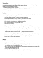
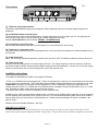
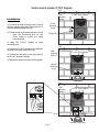
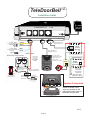
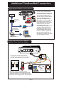
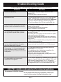
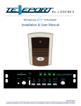
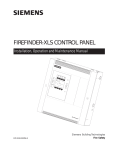
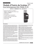
Ins tallation Manual
Revision 5 June 2003
TeleDoorB ell
Don't open your door to the unknown
TeleDoorB ell U nit
Ri ng On/Off Relay C ontacts Door S pkr 2
Door S pkr 1
Tele L ine In & Out
6A-7500 Martin Grove Rd. Woodbridge, ON. Canada L4L 8S9
Toll Free: 1.888.790.5900 E-mail: [email protected]
For complete information please visit our website at www.logenex.com
Page 1
Power Plug
TM
Contents
Safety Instructions and guidelines ...................................................
Introduction ......................................................................................
Features ...........................................................................................
Parts Listing .....................................................................................
Installation Instructions ....................................................................
Installation Diagram ..........................................................................
Additional Installation Diagrams .......................................................
Trouble Shooting ...............................................................................
Programming .....................................................................................
Pg 2
Pg 3
Pg 3
Pg 3
Pg 4
Pg 6
Pg 7
Pg 8
Pg 9
Warranty / Users Guide .....................................................................
pg 9
SAFETY INSTRUCTIONS
When using your telephone equipment, basic safety precautions should always be followed to reduce the risk of fire,
electric shock and injury to persons, including the following:
1. Read and understand all instructions.
2. Follow all warnings and instructions marked on the product
3. Unplug this product from the wall outlet before cleaning. Do not use liquid cleaners or aerosol cleaners. Use a damp
cloth for cleaning.
4. Do not use this product near water, for example, near a bathtub, wash bowl, kitchen sink, or a laundry tub, in a wet
basement, or near a swimming pool.
5. Do not place this product on an unstable cart, stand or table. The product may fall, causing serious damage to the
product.
6. This product should never be operated near or over a radiator or heat register. This product should not be placed in a
built-in installation unless proper ventilation is provided.
7. This product should be operated only from the type of power source indicated on the marking label. If you are not sure
of power supply to your home, consult your dealer or local Power Company.
8. Do not allow anything to rest on the power cord. Do not locate this product where the cord will be abused by persons
walking on it.
9. Do not overload wall outlets and extension cords as this can result in risk of fire or electric shock.
10. Never push objects of any kind into this product through cabinet slots as they may touch dangerous voltage points or
short out parts that could result in a risk of fire or electric shock. Never spill liquid of any kind on the product.
11. To reduce the risk of electric shock, do not dissemble this product, but take it to qualified service technician when
some service or repair is required. Opening or removing covers may expose you to dangerous voltages or other risks.
Incorrect re-assembly can cause electric shock when the appliance is subsequently used.
12. Unplug this product from the wall outlet and refer servicing to a qualified service personnel under the following
conditions:
* When the power supply cord or plug is damaged or frayed.
* If liquid has been spilled into the product.
* If the control unit has been exposed to rain or water.
* If the product does not operate normally by following the instructions. Adjust only those controls that are
covered by the operating instructions because improper adjustment of other controls may result in damage and
will require extensive work by a qualified technician to restore to normal operation
* If the product has been dropped or the housing has been damaged
* If the product exhibits a distinct change in performance.
13. Avoid using a telephone (other than cordless type) during an electrical storm. There may be a remote risk of electric
shock from lightning.
14. Do not use the telephone to report a gas leak near the leak.
DOC NOTICE:
Notice- The Canadian Department of Communications label identifies certified equipment. The certification means that the equipment meets certain
telecommunications network protective, operational and safety requirements. The Department does not guarantee the equipment will operate to the
user’s satisfaction.
Before installing this equipment, user should ensure that it is permissible to connect to the facilities of the local telecommunications company. The
equipment must also be installed using an acceptable method of connection. User should ensure that the telephone lines and metallic water pipe system
(if present) are electrical grounded.
Page 2
Introductions
Congratulations on your purchase of the TeleDoorBell, a system that offers enhanced security while providing
unparalleled convenience. The system can be used with or without a doorbell.
Operation is subject to the following Conditions:
1) This device may not cause harmful interference
2) This device may accept any interference including interference that may cause undesired operation.
Complies with Part 68, FCC Rules FCC REG NO. 5ERCAN-31264-OT-N REN: 0.8B
(DOC/CSA/UL approved)
Features
The TeleDoorBell is a telephone based doorbell system that provides the system user with the capability of
communicating with a door speaker from any installed telephone set, including cordless. Unmatched in convenience, this
unique new product provides the following features:
* System will work as a replacement or in parallel with any standard doorbell.
* Provides high-quality audio conversation capability with any connected door speaker.
* Unique telephone ringing when door speaker button depressed.
* Allows homeowner to select the door speaker by entering a unique touch-tone code from any telephone.
* Will provide toll restriction at the discretion of the owner.
* Rings telephones distinctively when door speaker button depressed.
* Relay closure to ring doorbell or a number of other devices.
* Can be set to ring doorbell only.
* Door speaker has LEDs for constant illumination.
* Supports speakerphone quality conversation between the telephone and the door speaker.
* The system gives a user two minutes to access door following the depression of the door speaker button.
* If the door speaker button is depressed, when the telephone is in use on an outside call, the user hears a beep
tone to alert that there is a visitor at the door. The user can then depress *4 on a touch-tone telephone to put the
telephone call on hold and connect to the door speaker. Depressing *4 again will return to the telephone call.
Note: this can only be used once and only after the door speaker button is depressed. Alternatively, a user can
hang up on the telephone call and then pick up the handset and they will be connected to the door speaker. (This
needs to be done within the two minute window. # can be used beyond the two minutes).
* A DTMF code selection (dialed from any connected telephone) allows the system user to access the door speaker
outside of the two-minute window.
* Relay closure activated by DTMF digit *5 or *8 allows door strike dry contact operation. (Normally Open NO).
* Toll Restriction, 1+ long distance, 011 international, or 1+976, user programmable.
* Password protection for programming which user can change to a personal 3-digit DTMF code.
* Progress tones to guide user while programming.
* *
Parts list
The TeleDoorBell system is shipped from the factory with the following components:
* TeleDoorBell control unit
* Speaker Unit with wall mounting plate
* CSA/UL approved class 2 Power Supply, Input 120VAC, 60Hz, Output 16Vac 250 mA. Note the system will also
work with a class 2 Power Supply Input 120VAC, Output 16-24Vdc 350 mA. Please make sure that the output
does not exceed 24 VDC or serious damage may occur.
* Two (2) modular RJ-11 Male open-ended patch cord. Used to splice and connect door speaker unit, door strike
and doorbell, to the TeleDoorBell system unit.
* RJ-45 8 pin male to male modular patch cord.
* Three (3) #6 wood screws for mounting
* Dimensions: Controller (17cmX17cmX4cm) Door-speaker (15.5cmX10.5cmX3cm)
Page 3
Connections
Ring On/Off Relay Contacts Door Spkr 2
1
2
Door Spkr 1
3
Fig 1
V-200
TeleDoorBell Unit
Tele Line In & Out
4
Power Plug
5
6
[1] Telephone ringer Selector Switch
This switch enables/disables ringing of the telephones. When positioned to the left, this switch enables ringing of the
telephones.
[2] Doorbell/Door Strike Connecting Jack
The centre two pins connect to the doorbell button. Doorbell will always ring if connected to the unit. The adjacent pairs
drives the door strike relay or other accessories (dry contact triggered devices only)
Internal TeleDoorBell Relays are all rated at: 24Volts , 1 Amp Maximum.
[3] Door Speaker Connecting Jacks
Each of these jacks enables a connection to door speaker for communicating to a point-of-entry.
[4] Telephone Line Connecting Jack
This jack provides connection to the incoming telephone line on the inner pair and connection to household telephone(s) on
the outer pair.
[5] Power Status LED
When "ON" this lamp indicates the presence of power to the unit, when "OFF" it indicates the absence of power to the unit.
[6] Power Supply Jack
This jack is the connecting point for AC power supply to the unit. The supply is typically 16 Vac at a minimum of 250 mA,
but can be as high as 20VAC, which will provide greater ringing power to the telephones. Can also use a 16-24 Vdc supply.
(Note: Do not exceed 24 VDC or serious damage can occur to the controller unit)
Installation Instructions
To complete the installation the installer must supply the following:
* RJ31X and/or CA38A disconnect and bypass jack. (This is an optional device, however, it is recommended in the event that
the unit needs to be disconnected. This will provide a bypass capability whereby the telephone line continues to work if the
TeleDoorBell unit needs to be removed from the telephone line. Note: If installation is done at a location that has an
existing alarm jack (RJ31X and/or CA38A) then ensure that the alarm is installed before the TeleDoorBell RJ31X and/or CA38A
jack. Otherwise, the alarm system may not have disconnect priority.
* Two plastic wall anchors to mount Door Speaker unit near a point of entry.
Installation of the system requires that the installer install a 4-conductor wire 22 AWG, (Max Length 250’) from the location of
the door speaker unit to the location of the system control unit. It is recommended that the system control unit be installed
near the point-of-entry of the customer's main telephone line. Please ensure that adequate AC power is available in the
general vicinity.
Mounting of the Door Speaker assembly: See Fig 2.
IMPORTANT NOTICE:
For added protection we strongly recommend you use surge protectors on both your power supply and on the C/O line
(phone line) to protect against lightning and other energy surges. This precaution may be extremely important in rural areas.
Page 4
Surface mount speaker D-100-F diagram
Fig 2
Wall /
Mounting
Surface
Installation
1) First drive an initial mounting screw 2” above
the door speaker wiring hole leaving about 1/4”
of screw shaft extending from wall.
Initial
Mounting
Screw
2) Thread wire through opening at bottom of unit
Note: We recommend that you use
silicon sealer to protect the wiring
around the hole
Wiring Hole
D-100-F Door Speaker
3) Hang The D-100-F speaker on initial
mounting screw
Fig 3
4) Secure the D-100-F speaker to the wall with
secondary mounting screw. See Fig 3
Wall /
Mounting
Surface
5) Connect the four wires to the wiring post of
the D-100-F speaker. See fig 4
D-100-F Door Speaker
6) Replace the wiring cover back on the speaker
Second
Mounting
Screw
Fig 4
Wall /
Mounting
Surface
D-100-F Door Speaker
Green
Yellow
Red
Black
Wire runs through
opening and into hole
Page 5
Replace Wiring cover
TeleDoorBell TM
Installation Guide
Ring On/Off Relay Contacts Door Spkr 2
To Door Strike
or any activation device
PRESS
To Door Strike
or any activation device
(3rd Relay)
RJ45 Modular Wire
(Supplied with Unit)
OUT
IN
RJ31X
(CA38A)
Data Jack
Blue
Grey
RJ11 Modular Wire
(Supplied with unit)
Green
Doorbell rewiring section
Door Bell
Front Door
Power Plug
Tele Line In & Out
Yellow
Black
PRESS
Existing
doorbell
Transformer
IN
OUT
Red
Use a 22 gauge 4
conductor wire (Max
Length 250 ft) to
connect from
controller to speaker
This contact
is activated
by pressing
door speaker
button
Transformer
Disconnect
switch and connect
wires together
Existing
doorbell switch
(to be removed)
Door Spkr 1
16V AC
Output
V-200
TeleDoorBell Unit
To
Phone
IN
OUT
RJ31X
(CA38A)
Alarm Jack
IN
OUT
Alarm jack
connection
only if alarm
monitored
Wire is reconnected
to the TeleDoorBell
TELCO IN LINE
from phone company
120V AC
Already connected
Audio
Video
Speaker Connection
- Remove access cover
- wire your speaker to the
appropriate colour code of
the audio terminal side
09-01
Page 6
Additional TeleDoorBell Connection
High-Speed Phone-Line Internet
TeleDoorBell Unit
TELCO
LINE IN
Ring On/Off Relay Contacts Door Spkr 2
Door Spkr 1
16V AC
Output
V-200
Power Plug
Tele Line In & Out
RJ45 Modular Wire
(Supplied with Unit)
OUT
IN
RJ31X
(CA38A)
Data Jack
RJ11 Modular Wire
(Supplied with unit)
IN
OUT
(Not supplied)
CALL
To
Phone
Phone Line
Demarcation
Block
To
Phone
To
Phone
IN
IN
OUT
Alarm jack connection
only if alarm monitored
Existing Phones on premise
Direct Cable to
the Demarcation
Block and isolated
from the Voice Line
OUT
RJ31X
(CA38A)
Alarm Jack
Data Filter
(supplied by
internet provider)
In order for the TeleDoorBell to
work you will have to isolate the
high-speed modem from the rest
of the regular telephone lines.
The two ways to go about this is
1) run an independent wire
(preferably shielded) directly to
the modem or 2) You could use
the existing wire to connect to
the modem but only if the wire is
isolated from the rest of the
phone cables (direct run).
This existing wire (if being used)
cannot be daisy-chained or be
transmitting any other voice or
data information other than the
internet connection. (make sure
that you install a Data Filter on
the Voice Line to block out any of
The high frequency noise)
High-Speed
Internet Modem
(supplied by internet provider)
Wiring connection for your computer /
Internet / Fax or Answering Machine
TeleDoorBell Unit
Ring On/Off Relay Contacts Door Spkr 2
Door Spkr 1
V-200
Tele Line In & Out
By using the existing wiring already
available at the phone jack. Use the spare
pair and connect these two wires to the
Power Plug
OUT
RJ45 Modular Wire
(Supplied with Unit)
IN
RJ31X
(CA38A)
Data Jack
OUT
IN
(Not supplied)
Wall
Existing
phone jack
New phone
jack for internet etc.
Existing
Phone Jack
Existing Cable
Spare Wires
Phone
Jacks
New Phone
Jack
IN
IN
Connection For:
Should you wish to use the answering in
conjunction with the TeleDoorBell, then simply
connect the machine as you would like the rest of
the phones (no rewiring required). You will require
Page 7
OUT
RJ31X
(CA38A)
Alarm Jack
- Computer
Internet / Fax
- Fax Machine
- Answering Machine
OUT
Alarm jack
connection
only if alarm
monitored
TELCO IN LINE
from phone company
Trouble Shooting Guide
In case of difficulty, try the following suggestions before seeking assistance
Problem
Solution
Controller not responding
1) Check your AC and power adapter, confirm LED Power
Indicator is ON
2) Check the power connection into the unit
My phones don't work
1) Are your phones wired into the (RJ31X and/or CA38A) data jack
(output). To test connection, remove the RJ45 wire from the
(RJ31X and/or CA38A) data jack which bypasses the TeleDoorBell
and connects the phones directly to the main incoming line
2) Check for any breaks in the RJ45 wire, including Data Jack
When door speaker is pressed, phones ring but
you have no audio communications to the door
1) Your Green or Yellow wires may be reversed, either at the
speaker or at the controller
2) The Red and Black wires may be reversed,
either at the speaker or at the controller
The TeleDoorBell is operating but the phones
don't ring when the speaker button is pressed
1) Your ringer switch located at the front of the controller may be
set to the OFF position
2) The Yellow wire is not properly connected to either the speaker
or the controller section of the speaker
3) One of the phones may be causing to much of a load; unplug
all phones and begin testing with one phone at a time till defective
phone is found
4) (With more than one telephone line): you may have wired the
controller to the wrong phone line
You have a dial tone feedback at the speaker
when door speaker button is pressed
Reverse the In and Out on the (RJ31X and/or CA38A) data jack.
When pressing * # * (for monitoring the door)
you get an operator recording (e.g. "this is an
invalid number") and you have no communication
to the speaker
1) You have attached the premise phones in parallel with the
TeleDoorBell across your C/O line
2) Your telephones may not be touchtone compatible, or the
touchtone switch may be set to off position
3) Check the yellow wire at both ends of speaker
4) (With more than one telephone line): you may have wired the
controller to the wrong phone line
On a gate installation: you have no audio
communication to the speaker
The unit has been designed to go a maximum of 250 ft with a 22
gauge wire. A possible solution to gain an additional 100 ft would
be to increase the gauge thickness (18 or 16). You can also
double up the Red and Black wires to give it the added gauge. A
long range system (500 to 1000 ft) is now available (LRV-200).
KSU / PBX Installation and requirements for commercial applications
We recommend a KSU-V200 Controller.
- The unit provides all the necessary requirements to hook up to a
commercial phone system including extended phone rings.
Page 8
User Manual
(Customers Copy)
Page 1 of 1
WARRANTY
Service Warranty
If servicing is needed for the TeleDoorBell, please contact your dealer. The dealer will be able to direct repairs and/or coordinate with the manufacturer.
TeleDoorBellTM products are warranted free from manufacturing defects for a period of one-year following installation. Faulty units will be repaired or
replaced at no extra charge to the User except shipping and insurance. The manufacturer assumes NO liability for consequential damage or for
damage resulting from abuse or improper operation.
Warranty
The TeleDoorBellTM, both main controller unit and speaker assembly is warranted to be free from manufacturing defects for ONE Year from date of
purchase. If the main unit and the speaker assembly, fails during this period, the failed part will be repaired or replaced at no charge, f.o.b. Toronto,
Ontario. To obtain warranty repair or replacement you must contact your dealer for instructions. Repaired or replaced units will have a ninety-day
warranty from the time the replacement or repair has been completed.
International Warranty
The warranty for international customers is the same as for any customer within Canada, with the exception that PPAL Industries Ltd. shall not be
responsible for any customs fee, shipping charges, taxes or VAT that may be due.
Disclaimer
The TeleDoorBellTM has been designed as a communications device. Customer understands and agrees that PPAL Industries will not be held liable for
any inconvenience, theft and invasion which may be of an indirect cause of the units failure, improper installation or the customers ability to use the
device. PPAL Industries will not be held liable for Telephone Lines being out of service or busy causing the TeleDoorBellTM to not function properly.
Although every effort has been made to make the TeleDoorBellTM as reliable as possible, the TeleDoorBellTM may fail to function as intended due to
the failure of components.
Conditions to Void Warranty
1) Damage incurred in shipping and handling 2) Damage caused by disaster such as fire, flood, wind, water / rain, earthquake, lightning and power
surges 3) damage caused by unauthorized attachment, alterations, modifications or foreign objects 4) Defects caused by failure to provide suitable
installation environment for the product 5) Damage arising out of any other abuse, mishandling or improper application of the product
PPAL Industries Ltd.
19 Kenview Blvd., Unit 31 Brampton, Ontario L6T 5G6 CANADA
Phone: (905) 790-8823 or 1 (888) 790-5900 Fax: (905) 595-1159 Email: [email protected]
How to use your TeleDoorBell
TM
1. If your doorbell rings or you hear the unique TeleDoorBell ring signal, pick up any telephone in the house within two minutes. You can
now talk to the person at the entrance.
2.If two minutes has expired then pick up any telephone and press
you to the door speaker.
Note: Using
# can be done at times
when no one has depressed the door
speaker button and provides the user
with a monitor function.
* *
3.While on a telephone conversation,
depression of the door speaker button will
cause a unique call indication tone to be
applied over the conversation. The
doorbell will also ring, if enabled. 4 can
be used to put the telephone call on hold
and connect to the door speaker. Using
*
4 again will return to the telephone call.
This hold feature can be used only once
per door speaker button depression.
Alternatively, a user can hang up the
active conversation and then pick up the
receiver and a connection will occur with
the door speaker. A user has two
*
minutes to do this, otherwise,
needs to be used.
*#*
*#*
on the touch tone keypad on your telephone. This will connect
Programming Your TeleDoorBell
Answering The Door
- Pick up hand set
- Pick up hand set
- Speak to person
- Press
If a door strike is connetcted
- Press
and / or
- Press
Strike#1
- Listen for 2 beeps
- Enter your passcode
(default is 111)
Strike#2
- Hang-up
Monitor A Door Station
- Pick up hand set
In the following, an acknowledgment of three beeps will indicate that the dialing
sequence is disabled, two beeps will indicate the dialing sequence is enabled.
- Press
Long Distance Restrictions
- Listen / Speak
- Hang-up
Putting Caller on HOLD
- (While speaking to a caller), a
visitor presses the door button, 2
beeps will be heard in your handset
- Press
- Disable/Enable
1+ dialing
- Disable/Enable
1+976 dialing
- Disable/Enable
011 dialing
Change Passcode
-Enter
Passcode
Mode
- Listen for 2 beeps
-Enter New
Passcode
- Speak to person at the door
4. If a door strike system has been
installed, to automatically open a door or
a gate, a user can activate it by
- Press
to
return speaking to caller
REMEMBER:
The TeleDoorBell will lose its programming and
return to factory default settings, including
password, if the power goes out.
depressing
5 / 8 on the keypad
while connected to the speaker. This will cause a five second contact closure and open the door or gate automatically.
*
*
6A-7500 Martin Grove Rd. Woodbridge, ON. Canada L4L 8S9
Toll Free: 1.888.790.5900 E-mail: [email protected]
For complete information please visit our website at www.logenex.com