1
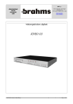
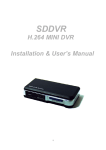
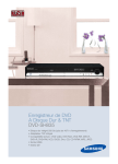
DVR4MQA – DIGITAL 4-CHANNEL RECORDER
1. Introduction
Thank you for choosing the DVR4MQA. It can be used as a replacement for both a time-lapse VCR and a quad/
multiplexer in a security installation. Read the manual carefully before bringing this device into service.
a) Safety Prescriptions
•
•
•
•
•
•
•
•
Handle this device with care.
Do not expose this device to direct sunlight.
Do not use this device near water and protect it against any possible contact with water.
Do not unplug the power connector before you've correctly switched the device off.
Use this device solely with the included power adapter.
Unauthorised attempts to repair may result in fire, electroshock or other hazards. Do not open the housing.
This device should be installed and serviced by a qualified person and conform to all local codes.
Do not switch the power ON and immediately (± 3 sec.) OFF again.
b) Features
•
•
•
•
•
•
•
•
•
•
•
•
•
•
Thanks to the wavelet compression format, this device replaces both a time-lapse VCR + a multiplexer/quad.
4 audio inputs ; 2 audio outputs (mono).
OSD (on-screen display) and remote control via Video Web Server (VWS2) and/or PC.
PIP (picture in picture) and POP (picture on picture) functions during live viewing.
Motion detection + motion trigger recording function.
Alarm input & output function
Video loss detection on each channel
Linear zoom (x2 - x4)
Multiplexer & Quad recording mode switching
recording rate: full size up to 30 images/second ; quad size up to 120 images/second
Supports 1 removable HDD with hot-swap capability, IDE type
Quick-search mode: search a fragment by time/date, alarm, full, motion list.
Password protection
RS232 and RS485 communication protocol.
c) Specifications
Video Format
HDD Storage
Record Mode
Camera Input Signal
Main/Call Monitor Output
Audio Input
Audio Output
Motion Detection Area
Motion Detection Sensitivity
Video Loss Detection
Display Refresh Rate
Recording Refresh Rate
Dwell Time
DVR4MQA
NTSC/EIA or PAL/CCIR
1 removable IDE type HDD, UDMA 66 or above
manual / alarm / timer / motion
Composite video signal 1Vp-p/75Ω BNC, 4 channels
Composite video signal 1Vp-p/75Ω BNC
4 RCA audio inputs
2 RCA mono audio outputs
16x12 targets per camera
99 levels
yes
240ips (NTSC), 200ips (PAL)
30ips (NTSC), 25ips (PAL)
programmable (1~15 sec)
-1-
Picture-in-Picture
Key Lock
Picture Zoom
Camera Title
Video adjustable
Alarm Input
Alarm Output
Remote Control
Time Display Format
Power Source
Power Consumption
Operating Temperature
RS232C / RS485 (bps)
Dimensions
Weight
yes (movable)
yes
x2~x4 (movable)
8 characters max.
Hue/colour/contrast/brightness
TTL input, high (5V), low (GND)
COM / NO / N.C.
RS232 or RS485
YY/MM/DD ; DD/MM/YY ; MM/DD/YY ; OFF
AC 90-220V, 47~63Hz
< 32W
10 – 40°C
115200 ; 57600 ; 19200 ; 9600 ; 4800 ; 3600 ; 2400 ; 1200
343 x 223 x 59mm (W x D x H)
2.05kg
2. Installation
a) Contents
Your DVR4MQA should come with the following items:
•
•
•
•
•
•
a digital quad recorder with HDD tray
2 tray keys
power adapter + cable
user manual
demounted 15-pin connector accessory pack
HDD connector + screws accessory pack
b) Connection with cameras
DVR4MQA
-2-
c) RS232 Remote Protocol
You can use the PC keyboard to simulate the DMR keypad.
DATA: REMOTE PROTOCOL using 8-bit data – 1 start bit – 1 stop bit
FUNCTION
KEY_MENU
KEY_SEARCH
KEY_ENTER
KEY_QUAD
KEY_ZOOM
KEY_PIP
KEY_SLOW
KEY_REC
KEY_LEFT
KEY_UP
CODE
0 x 4D
0 x 73
0 x 0D
0 x 51
0 x 5A
0 x 70
0 x 53
0 x 72
0 x 4C
0 x 55
ASCII
M
s
ENTER
Q
Z
p
S
r
L
U
FUNCTION
KEY_PLAY
KEY_DOWN
KEY_RIGHT
KEY_POWER
KEY_ KEY_LOCK
KEY_CH1
KEY_CH2
KEY_CH3
KEY_CH4
TIMER REC PROCEED
CODE
0 x 50
0 x 4E
0 x 52
0 x 57
0 x 4B
0 x 31
0 x 32
0 x 33
0 x 34
0 x 54
3. Configuration
a) Installing HDD
1) Removing HDD Tray
1. Open the lock protection cap and set the tray lock to position B (see figures at the right).
In position A (cf. drawing on the right), the tray is locked and cannot be removed.
In position B, the tray is unlocked and can be removed.
The key lock must be in position A for the device to operate properly.
2. Pull out the tray. If there is a HDD inside, loosen all the screws on the tray and remove the
HDD from the tray. If you want to install another HDD, remove the connector from the HDD.
2) Installing the Hard Drive into the Tray
1. Put the connector on the HDD to be installed. Make sure the jumper on the HDD is
set to master (for some HDDs, the jumper should be on CS (cable select)).
2. Put the HDD into the tray. The connector should match the bottom plate extension.
Position the HDD in such a way that the first pin aligns with the arrowhead as
indicated on the sticker on the bottom plate extension.
3. Secure the HDD with the enclosed screws.
4. Reverse the tray (so the bottom plate faces down) and insert it into the device.
5. Lock the tray by turning the key lock clockwise and close the lock protection cap.
3) Max. Recording Time & Compatible HDD's
The recording time depends on the recording speed and quality. These times are valid for a 250GB HDD.
Below data are obtained from an actual test during which normal TV programs were recorded.
DVR4MQA
-3-
ASCII
P
N
T
W
K
1
2
3
4
T
NTSC SYSTEM
IPS
multiplex
quad-field
quad-frame
Best
High
Normal
Basic
Best
High
Normal
Basic
Best
High
Normal
Basic
30
50hr
62hr
100hr
167hr
47hr
58hr
95hr
158hr
24hr
29hr
48hr
79hr
15
100hr
125hr
200hr
333hr
95hr
118hr
190hr
316hr
48hr
59hr
80hr
158hr
8
187hr
235hr
375hr
625hr
177hr
223hr
356hr
593hr
89hr
112hr
178hr
296hr
4
375hr
468hr
750hr
1250hr
356hr
445hr
712hr
1187hr
178hr
223hr
356hr
594hr
2
750hr
937hr
1500hr
2500hr
712hr
890hr
1425hr
2375hr
356hr
445hr
713hr
1188hr
1
1500hr
1875hr
3000hr
5000hr
1425hr
1781hr
2850hr
4750hr
713hr
890hr
1425hr
2375hr
Best
High
Normal
Basic
Best
High
Normal
Basic
Best
High
Normal
Basic
25
50hr
62hr
102hr
168hr
48hr
58hr
98hr
159hr
24hr
29hr
49hr
79hr
12
104hr
131hr
210hr
350hr
98hr
124hr
200hr
332hr
49hr
62hr
100hr
166hr
6
210hr
265hr
422hr
704hr
200hr
251hr
400hr
668hr
100hr
125hr
200hr
334hr
3
422hr
527hr
844hr
1406hr
400hr
500hr
801hr
1335hr
200hr
250hr
400hr
667hr
2
633hr
792hr
1266hr
2110hr
601hr
752hr
1202hr
2004hr
300hr
376hr
601hr
1002hr
1
1266hr
1583hr
2542hr
4218hr
1202hr
1503hr
2414hr
4007hr
601hr
751hr
1207hr
2003hr
PAL SYSTEM
IPS
multiplex
quad-field
quad-frame
COMPATIBLE HDD MODELS
Manufacturer
HITACHI
HITACHI
HITACHI
IBM
IBM
Maxtor
Maxtor
Maxtor
Maxtor
Maxtor
Seagate
Seagate
Seagate
Western Digital
Western Digital
Western Digital
DVR4MQA
Model
Deskstar 180GPX (120GB)
Deskstar 7K250, HDS722516VLAT20
Deskstar 7K250, HDS722525VLAT80
Deskstar 120GXP (80GB)
Deskstar 120GXP (120GB)
DiamondMax 536DX (60GB) 4W060H4
DiamondMax Plus 9
DiamondMax Plus 9, Model#6Y120L
DiamondMax Plus 9, Model#6Y160L0
MaxLine Plus II, Model#7Y250P0
Barracuda ATA IV ST380021A
Barracuda ATA V, ST3120023A
Barracuda 7200.7 Plus, ST3160023A
Caviar WD1200BB-00CAA1
Caviar WD2000BB-00DWA0
CaviarSE WD2500JB
-4-
Capacity
120GB
160GB
250GB
80GB
120GB
60GB
80GB
120GB
160GB
250GB
80GB
120GB
160GB
120GB
200GB
250GB
Rotation
7200rpm
7200rpm
7200rpm
7200rpm
7200rpm
5400rpm
7200rpm
7200rpm
7200rpm
7200rpm
7200rpm
7200rpm
7200rpm
7200rpm
7200rpm
7200rpm
b) Control Panel Description
1.
2.
3.
4.
5.
6.
7.
8.
9.
REMOVABLE HDD CARTRIDGE & KEYHOLE
CAMERA: press one of the buttons to select that channel
REC:
to start recording immediately.
PLAY:
to play recorded video.
PAUSE/▲: pauses the fragment. In setup mode it works as an up button.
STOP/▼: stops playback or recording. In setup mode it works as a down button.
REW /◄: to rewind in PLAY and PAUSE mode. In setup mode it works as a left button.
FF / ►:
to wind forward in PLAY and PAUSE mode. In setup mode it works as a right button.
LEDs:
HDD: HDD status
HDD FULL: HDD is full
ALARM: alarm is armed (when alarm is triggered, LED is flashing)
TIMER: the device is programmed to record
PLAY: recorded material is being reproduced
REC: the device is recording
10. MENU:
Press this key to access the main menu.
11. ENTER:
to confirm data or a selection.
12. SEARCH: opens the search menu
13. ZOOM:
press ZOOM to enlarge the displayed picture
14. PIP/+:
Press once for PIP, twice for POP. In setup mode it works as a "+" button to change a value.
15. QUAD/-:
displays all 4 channels simultaneously. In setup mode it works as a "-" button to change a value.
16. SLOW:
slows down the play speed.
17. POWER:
Press this button to power on, and press it again to power off.
c) Back Panel Description
18.
19.
20.
21.
22.
23.
24.
25.
POWER: connect the provided adapter to this connector and plug it into the mains.
External I/O: the device can be controlled remotely by an external device or trigger mechanism.
VIDEO inputs 1-4: to connect video sources such as cameras.
MAIN MONITOR: to connect the main monitor.
CALL MONITOR: to connect the call monitor. This monitor will show the triggered channel in case of an alarm.
AUDIO IN: 1 input per channel. Only 1 input can be recorded during 1 session. Only available when IPS≥25.
AUDIO OUT: 2 mono audio outputs. Only available when IPS≥25.
FAN: for ventilation purposes ; do not block this opening
DVR4MQA
-5-
25-pin COM port
9-pin COM port
PIN 1: RS232-TX + PIN 2: RS232-RX: This device can be controlled remotely by an external device or control
system, such as a control keyboard, using RS-232 serial communications signals.
PIN 3/4/5/6: ALARM INPUT 1/2/3/4: By connecting these pins to GND (pin 9), the DVR4MQA will start recording and
the buzzer will be on. Triggering depends on the set level (high/low) under Menu/Camera/Alarm.
PIN 7: EXTERNAL ALARM NC + PIN 8: EXT. ALARM NO: During normal functioning COM is connected with NC
and not with NO. When there is an alarm trigger, COM disconnects from NC and connects with NO.
PIN 9: GND: GROUND
PIN 10: RS485-B + PIN 11: RS485-A: This device can be controlled remotely by an external device or control
system, such as a control keyboard, using RS-485 serial communications signals.
PIN 12: DISK FULL: When the HDD is full, it sends a trigger signal to a possible next DVR4MQA. Normally this
signal is high ; when the disk is full it becomes low.
PIN 14: ALARM RESET: An alarm can be disabled by connecting pin 14 to pin 9 (GND). An external signal to this
pin can reset both the alarm output signal and the internal buzzer. Normally this signal is high.
PIN 15: EXTERNAL ALARM COM: During normal functioning COM is connected with NC and not with NO. When
there is an alarm trigger, COM disconnects from NC and connects with NO.
4. Operation
a) Power on the Device
Before turning the power ON, make sure a HDD is installed and the tray has been locked. If no HDD is installed, the
DVR4MQA will function as a 4-channel multiplexer.
1. Connect the DVR4MQA to a mains outlet by means of the supplied AC power cord and adapter and press the
POWER button (p.5 #17). The red LED indicator next to it lights up: the DVR is in standby mode.
2. Press the POWER button, the POWER LED will turn to orange and all the other LEDs (p.5 #9) will turn red. The
device takes anywhere from 5 to 15 seconds to boot, all the while displaying the message "HDD detecting". When
the boot is complete and the HDD is detected, the LED will turn to green and the ALARM LED will be lit.
When no HDD is detected, "HDD not found" appears for 3 seconds and the device goes to 4CH multiplexer mode.
3. Set the system time before operating the DVR4MQA (see §5-b-11 on p.9).
NOTE: to switch from NTSC to PAL or vice versa, power down the device and unplug the AC power cord. For NTSC,
press POWER+FF before reconnecting the cord ; for PAL, press POWER+REW.
DVR4MQA
-6-
b) Recording
Your DVR4MQA offers a variety of recording modes. You can set it up to record continuously or programmed, or only
to record events ; you can even set the recording speed and resolution. All these options are set through the system
menu. If there should be a power cut during recording, the device will automatically resume recording when the
power returns. The original recording set-up will be respected.
2002 - JAN - 01
01:02:03
There are 4 recording modes, during which the screen will be as displayed on
● OW
the right. Date and time are displayed, with underneath these symbols:
the recording mode symbol, followed by “●” = recording, and “OW” = HDD in
overwrite mode – when the HDD is full, the oldest data will automatically be overwritten.
When the HDD is not in overwrite mode, the OW location will show the capacity left on the HDD ; at 5GB, “5GB” will
appear in orange and a buzzer will sound. The same will happen for 4GB, 3GB, 2GB and 1GB.
1) Alarm Recording
The DVR4MQA is triggered by an alarm input and will start to record immediately, with the
The recording speed & quality will be as set in the alarm recording mode set-up.
symbol appearing.
2) Motion Trigger Recording
Recording can be triggered by motion detection. The symbol will appear on the triggered channel.
The recording speed & quality will be as set in the RECORD menu.
3) Programmed Recording
The DVR4MQA will follow the timer set-up to record and the recording speed & quality as set in the TIMER menu.
The icon will appear.
4) Manual Recording
You can press the REC button to start recording immediately. The symbol will appear.
The recording speed & quality will be as set in the RECORD menu.
c) Playback
Press PLAY: the DVR4MQA will go into play mode and will start playing the last recording.
1) Fast Forward (F.F.) & Fast Rewind (F.R.)
• Press PLAY then press ► for fast forward searching. Press once for double speed, press twice for quadruple
speed, 3 times for 8x, 4 times for 16x and 5 times for 32x (maximum speed).
• Press PLAY then press ◄ for fast rewind searching. Press once for double speed, press twice for quadruple
speed, 3 times for 8x, 4 times for 16x and 5 times for 32x (maximum speed).
2) Slow Forward (S.F.) & Slow Rewind (S.R.)
• Press PLAY then press SLOW for slow play at half speed. Press ► once for quarter speed, 2 times for 1/8x, 3
times for 1/16x and 4 times for 1/32x (minimum speed).
• Press PLAY then press SLOW for slow play. Press ◄ once for half speed, press twice for quarter speed, 3 times
for 1/8x, 4 times for 1/16x and 5 times for 1/32x (minimum speed).
DVR4MQA
-7-
3) Pause
Press PLAY then press PAUSE, the image will be paused.
4) Stop
Press STOP and the DVR4MQA will stop all actions and display the incoming signal.
5) Image by image
• Press PLAY and PAUSE to pause the image. Press ► to go to the next image ; keep it pressed to go faster.
• Press PLAY and PAUSE to pause the image. Press ◄ to go to the previous image; keep it pressed to go faster.
When the very first image is shown, the DVR4MQA cannot return further.
e) Video Loss
"LOSS" will appear on the screen if the DVR4MQA does not receive a video signal.
f) Key Lock
Press MENU and ENTER simultaneously to lock the control keys.
Press MENU and ENTER simultaneously, enter the password (default: 0000) and press ENTER to unlock the keypad.
Locking and unlocking the keypad can also be used to switch users by entering another password.
5. System Set-up
a) Open Main Menu
Press the MENU button on the front of the device. The screen you see on the right
will be displayed.
You can use the ▲, ▼, ► and ◄ buttons to move around in the menu.
You can use “+” and “-“ to increase of decrease the displayed values.
Use ‘ENTER’ to open a submenu/option under a submenu.
Use MENU to complete the modification of a menu option or to exit a menu.
DVR4MQA
-8-
(MENU)
TIMER
CAMERA
RECORD
ALARM
DWELL
PIP
MOTION
DISPLAY
REMOTE
USER
SYSTEM
EVENT
b) System Menu
(MENU)
TIMER
CAMERA
RECORD
ALARM
DWELL
PIP
MOTION
DISPLAY
REMOTE
USER
SYSTEM
EVENT
Press the MENU button and press ▲or ▼until 'SYSTEM' is selected (cf. figure on the right).
Press ENTER to enter the system set-up menu.
A screen as shown on the right will be displayed.
All instructions below start from this point.
1) AUDIO INPUT
To choose the channel to be recorded
(the audio of only 1 channel can be recorded).
2) BUZZER
If the buzzer is ‘ON’,
it will buzz when there is a motion detection.
(System)
AUDIO INPUT
1
BUZZER
ON
EXT ALARM
ON
VLOSS ALARM
ON
MOTION ALARM
ON
KEY MUTE
YES
HDD OVERWIRTE
YES
MESSAGE LATCH
YES
DATE DISPLAY
D/M/Y
DATE
2003-MAY-21 (WED)
TIME
22:38:29
CLEAR HDD
YES
SYSTEM RESET
YES
3) EXT. ALARM
If it is ON, the external alarm output will be triggered when there is a motion detection.
4) VLOSS ALARM
If it is ‘ON’ and there is video loss, it can trigger the buzzer, send out an external alarm and start recording.
5) MOTION ALARM
If it is ‘ON’ and there is a motion detection, it can trigger the buzzer, send out an external alarm and start recording.
6) KEY MUTE
If it is set to ‘YES’, there will be no sound when you press a key.
7) HDD OVERWRITE Set-Up
If it is set to ‘YES’ and the HDD is full, previously recorded files will be overwritten without further warning notice.
8) MESSAGE LATCH Set-Up
If it is set to ‘NO’ (default setting), DVR messages will disappear after 10 seconds.
If it is set to ‘YES’, the DVR messages will remain on screen.
NOTE: video loss, alarm and motion messages will disappear after the set Alarm Duration time.
9) DATE DISPLAY Set-Up
Set the date appearance as Y/M/D, M/D/Y, D/M/Y or off.
10) DATE Set-Up
Set the date.
11) TIME Set-Up
Set the time.
12) CLEAR HDD Set-Up
Set this line to ‘YES’ and press ENTER. A screen as displayed on the right will appear.
Press ► to clear the HDD or ◄ to cancel.
13) SYSTEM RESET Set-Up
To set all system settings back to factory default settings. Select ‘YES’ and press ENTER.
DVR4MQA
-9-
All Data in HDD
Will Be Cleared
Are you sure?
(◄: No ►: Yes)
c) Timer Programming
Press the MENU button on the front of the device and press ▲or ▼until 'TIMER' is
selected (cf. figure on the right).
Press ENTER to enter the timer menu. A screen as shown below will be displayed.
(TIMER)
DAY
START END
DAILY 01:00 22:00
OFF
00:00 00:00
OFF
00:00 00:00
OFF
00:00 00:00
OFF
00:00 00:00
OFF
00:00 00:00
OFF
00:00 00:00
TIMER ENABLE: NO
IPS
15
15
15
15
15
15
15
QLT
BEST
BEST
BEST
BEST
BEST
BEST
BEST
MODE
Q-FR
Q-FI
Q-FI
Q-FR
MUX
Q-FR
Q-FI
(MENU)
TIMER
CAMERA
RECORD
ALARM
DWELL
PIP
MOTION
DISPLAY
REMOTE
USER
SYSTEM
EVENT
1) DAY
Press ENTER to set the day selection of the first line.
Press + or - to select the day set-up:
DAILY : every day
MON / TUE / WED / THU / FIR / SAT / SUN: one day only
MO-FR : Monday to Friday
SA-SU : Saturday & Sunday
JAN-01 : specific date.
2) START
Set the recording start time (HH:MM).
3) END
Set the recording end time (HH:MM).
NOTE: if you want to record from 23:30 on Sunday to 00:20 on Monday, you will need to set 2 lines: one on Sunday
from 23:30 to 23:59 and one on Monday from 00:00 to 00:20. One line from Sunday 23:30 to 00:20 will result in
the DVR4MQA recording from Sunday 23:30 to 00:20 on the next Sunday…
4) IPS
Select the number of images per second (IPS).
NTSC : 1, 2, 4, 8, 15, 30 ; PAL: 1, 2, 3, 6, 12, 25
5) QUALITY
Select the recording quality: BEST, HIGH, NORM or BASE.
6) MODE
Select the recording mode:
Q-FR = quad-frame: all 4 channels simultaneously
Q-FI = quad-field: all 4 channels simultaneously at lower resolution
MUX = multiplex: the 4 channels consecutively
7) TIMER ENABLE
If you set it to ‘YES’ and press MENU, you can see a diagram as
shown at the right that displays what you’ve programmed:
DVR4MQA
- 10 -
d) CAMERA
Press the MENU button on the front of the device and press ▲or ▼until 'CAMERA' is
selected (cf. figure on the right).
Press ENTER to enter the camera menu. A screen as shown below will be displayed.
(MENU)
TIMER
CAMERA
RECORD
ALARM
DWELL
PIP
MOTION
DISPLAY
REMOTE
USER
SYSTEM
EVENT
1) TITLE
A title can be given to each channel/camera. Initially each title is the channel number.
2) ALARM
Select LOW / OFF / HIGH for alarm polarity. The default value is LOW.
3) REC
Select if the channel has to be recorded or not. When it is set to ON and the alarm is triggered for that channel, it will
be recorded more frequently, e.g. if channel 1 is triggered, the recording sequence will be 1-2-1-3-1-4-…
4) BT (Brightness) / CT (Contrast) / CL (Colour) / HUE
Adjust the brightness, contrast, colour and hue for each channel ; the levels can be set from 0 to 63.
e) Recording Mode
Press the MENU button on the front of the device and press ▲or ▼until 'RECORD' is
selected (cf. figure on the right).
Press ENTER, the following screen will appear:
(RECORD)
RECORD IPS: 30
RECORD QUALITY: NORMAL
RECORD MODE: FRAME
1) RECORD IPS
Select the number of images per second (IPS).
NTSC : 1, 2, 4, 8, 15, 30 ; PAL: 1, 2, 3, 6, 12, 25
2) QUALITY
Select the recording quality: BEST, HIGH, NORM or BASE.
3) RECORD MODE
Select the recording mode:
Q-FR = quad-frame: all 4 channels simultaneously
Q-FI = quad-field: all 4 channels simultaneously at lower resolution
MUX = multiplex: the 4 channels consecutively
DVR4MQA
- 11 -
(MENU)
TIMER
CAMERA
RECORD
ALARM
DWELL
PIP
MOTION
DISPLAY
REMOTE
USER
SYSTEM
EVENT
f) Alarm
Press the MENU button on the front of the device and press ▲or ▼until 'Alarm' is selected
(cf. figure on the right).
(ALARM)
Press ENTER, the following screen will appear:
ALARM ENABLE
ALARM DURATION
RECORD IPS
QUALITY
RECORD MODE
1) ALARM ENABLE
If it is set to ‘YES’, the alarm will be triggered by any event occurring.
YES
10 SEC
60
NORMAL
FRAME
(MENU)
TIMER
CAMERA
RECORD
ALARM
DWELL
PIP
MOTION
DISPLAY
REMOTE
USER
SYSTEM
EVENT
2) ALARM DURATION
Set the alarm duration. Default setting is 10 SEC. Other settings are: 15 SEC, 20 SEC, 30 SEC, 1 MIN, 2 MIN, 3
MIN, 5 MIN, 10 MIN, 15 MIN, 30 MIN, ALWAYS, AUTO.
3) RECORD IPS
Select the number of images per second during an alarm recording: NTSC: 1, 2, 4, 8, 15, 30; PAL: 1, 2, 3, 6, 12, 25.
4) QUALITY
Select the recording quality: BEST, HIGH, NORM or BASE.
5) RECORD MODE
Select the recording mode during an alarm recording:
Q-FR = quad-frame: all 4 channels simultaneously
Q-FI = quad-field: all 4 channels simultaneously at lower resolution
MUX = multiplex: the 4 channels consecutively
g) DWELL
Press the MENU button and press ▲or ▼until ‘DWELL’ is selected (cf. figure on the right).
Press ENTER ; the following screen will appear:
CAM1
CAM2
CAM3
CAM4
(DWELL)
NORM ALARM
01
01
01
01
01
01
01
01
1) NORM
Set the time each channel is displayed during sequential showing on the call monitor.
The level can be set from 1 to 15 seconds or OFF.
(MENU)
TIMER
CAMERA
RECORD
ALARM
DWELL
PIP
MOTION
DISPLAY
REMOTE
USER
SYSTEM
EVENT
2) ALARM
Set the time each channel is displayed when the alarm input is triggered.
The level can be set from 1 to 15 seconds or OFF.
h) PIP
Press the MENU button and press ▲or ▼until ‘PIP’ is selected (cf. figure on the right).
Press ENTER ; the following screen will appear:
(PIP)
1) FULL SCREEN
Set the channel to be displayed full screen.
FULL SCREEN
PIP SCREEN
POSITION
2) PIP SCREEN
Set the channel to be displayed in a 1/9 size ‘insert’.
3) POSITION
There are 6 position settings: D/L, D/M, D/R, U/L, U/M, U/R
DVR4MQA
- 12 -
CAM 1
CAM 2
D/R
(MENU)
TIMER
CAMERA
RECORD
ALARM
DWELL
PIP
MOTION
DISPLAY
REMOTE
USER
SYSTEM
EVENT
i) MOTION
Press the MENU button and press ▲or ▼to select 'MOTION' (cf. figure on the right).
Press ENTER to enter the motion menu. A screen as shown below will be displayed.
(MOTION)
CAM1
CAM2
CAM3
CAM4
SEN ND-NUM RE
70
03
64
70
03
64
70
03
64
70
03
64
DET
ON
OFF
ON
ON
AREA
AREA
AREA
AREA
MOTION RECORD: ON
DAY START END
DAILY 00:00
00:00
(MENU)
TIMER
CAMERA
RECORD
ALARM
DWELL
PIP
MOTION
DISPLAY
REMOTE
USER
SYSTEM
EVENT
1) SEN (Sensitivity)
Set the sensitivity of the pixel-based motion detection feature from 1 (high) to 99 (low sensitivity). Default value is 70.
2) MD-NUM (Motion Detection Number)
Set the number of targets in which motion must occur for the alarm to be triggered (from 1 to 99 – cannot be more
than the number of targets set under AREA).
3) RE (Reference)
Set the reference image to which the current screen is compared (1-99). For example, value 64 would compare the
current image to the 64th image before that. A higher value may increase the sensitivity.
4) DET (Detection)
The motion detection on each channel can be turned ON or OFF individually.
5) AREA
Press the ENTER button when this option is selected to set the pixel-based motion detection area for each channel.
Green targets represent the motion detection area and purple targets represent detected motion.
Use these controls to modify the motion detection area (see figures p.5):
▲▼►◄: navigates between targets, ZOOM turns selected target ON/OFF
‘-‘ turns all targets on the screen ON/OFF ; ‘+’ turns all targets on the selected row ON/OFF
NOTE: when DET is ON, you must set a motion detection area or there will be no triggering.
The red block indicates on which field you are positioned ; the green area indicate which fields are set to ON.
Upon a motion detection, the affected fields turn purple ; after ALARM DURATION, the original settings are restored.
DVR4MQA
- 13 -
6) MOTION RECORD
When DET is ‘ON’, you can set up the MOTION RECORD function.
1. When MOTION RECORD is set to ON: the DVR4MQA will automatically start to record when there is a motion
detection. The scanning sequence will be modified and will appear on the monitor. Note that the motion
detection recording will use the ALARM DURATION time settings and that the set time will restart from zero each
time there is a motion detection (also when the device is still recording from a previous detection).
2. When MOTION RECORD is set to OFF, the icon will still appear and when the DVR4MQA is in record mode,
the scanning sequence will be modified.
7) DAY / START / END
To set the DAY and START/END times for motion trigger recording.
j) DISPLAY
Press the MENU button and press ▲or ▼to select 'DISPLAY' (cf. figure on the right).
Press ENTER to enter the display menu. A screen as shown below will be displayed.
(DISPLAY)
TITLE DISPLAY
OSD COLOR
LOSS SCREEN
TIME POSITION
YES
YELLOW
GREEN
NORMAL
1) TITLE DISPLAY
Determine whether the title of the channel should appear on the monitor or not.
(MENU)
TIMER
CAMERA
RECORD
ALARM
DWELL
PIP
MOTION
DISPLAY
REMOTE
USER
SYSTEM
EVENT
2) OSD COLOR
Set the OSD colour: YELLOW, WHITE, GREEN, BLACK, BLUE, RED, PINK or CYAN.
3) LOSS SCREEN
Select a colour for when there is no image (GREEN, BLACK or BLUE) or retain the last image (RETAIN).
4) TIME POSITION
Set the position of the time display on the monitor: NORMAL or CENTER.
k) Remote Protocol Set-Up
Press the MENU button and press ▲or ▼to select 'REMOTE' (cf. figure on the right).
Press ENTER to enter the remote menu.
A screen as shown on the right will be displayed.
(REMOTE)
REMOTE MODE
BAUD RATE
ID
RS-485
9600
255
1) REMOTE MODE
Set the remote control protocol for connection with a computer: RS-232 or RS-485.
(MENU)
TIMER
CAMERA
RECORD
ALARM
DWELL
PIP
MOTION
DISPLAY
REMOTE
USER
SYSTEM
EVENT
2) BAUD RATE
Set the baud rate: 115200 / 57600 / 19200 / 9600 / 4800 / 3600 / 2400 / 1200
3) ID
You can use the RS232 remote protocol to control more than 1 DVR4MQA. Set the ID number from 000 to 255.
DVR4MQA
- 14 -
l) USER
Press the MENU button and press ▲or ▼to select 'USER' (cf. figure on the right).
Press ENTER to enter the user menu.
A screen as shown on the right will be displayed.
(USER)
SUPERVISOR
USER 1
USER 2
USER 3
USER 4
USER 5
USER 6
USER 7
PASSWORD
0000
0000
0000
0000
0000
0000
0000
0000
(MENU)
TIMER
CAMERA
RECORD
ALARM
DWELL
PIP
MOTION
DISPLAY
REMOTE
USER
SYSTEM
EVENT
1) USER
Up to 8 users can be set.
‘SUPERVISOR’ can control all functions ; ‘USER’ cannot view the menu settings and cannot clear the event list.
2) PASSWORD
For each account, a password of 4 characters can be set (default: 0000).
To switch users, press ENTER and MENU simultaneously to lock the keypad ; press ENTER and MENU
simultaneously again and enter the new user’s password and press ENTER.
m) EVENT
Press the MENU button and press ▲or ▼to select 'EVENT' (cf. figure on the right).
Press ENTER to view the event pages.
A screen as shown on the right will be displayed.
Possible event codes:
DISK FULL: HDD is full
PWR REST: power restored
M-HD REMS: HDD removed
M-HD REPL: HDD replaced
M-HD ERR: HDD error
M-HD WARM: HDD warning
K UNLOCKS: keys are unlocked
DMA ERROR: DMA (direct memory access) error
C1 VLOSS: Video loss on channel 1
C2 ALARM: external I/O alarm trigger on channel 2
C3 MOTION: motion detection trigger on channel 3
SYSTEM ERROR: system might fail
C1 VLOSS
C2 ALARM
K UNLOCKS
M-HD ERR
M-HD WARM
PWR REST
DMA ERROR
M-HD REPL
26-DEC-2002
26-DEC-2002
26-DEC-2002
26-DEC-2002
26-DEC-2002
26-DEC-2002
26-DEC-2002
26-DEC-2002
03:00:00
03:00:00
03:00:00
03:00:00
03:00:00
03:00:00
03:00:00
03:00:00
▲• ▼•• CLEAN
(MENU)
TIMER
CAMERA
RECORD
ALARM
DWELL
PIP
MOTION
DISPLAY
REMOTE
USER
SYSTEM
EVENT
Press ◄ or ► to switch pages (16 events on 1 page) and press ▲or ▼to clear the EVENT list.
6. Zoom
Press ZOOM to enlarge the main picture. A picture-on-picture field appears on the zoomed image, of which the
zoomed area can be moved about.
PIP button: zoom in
QUAD button: zoom out
ZOOM (second time) to leave zoom function.
CAM 1-4 button: channel full screen
▲, ▼, ► ◄: to move the zoom position.
DVR4MQA
- 15 -
7. Search
Press the SEARCH button ; a screen as shown on the right will be displayed.
1) LAST RECORDING
Press ▲or ▼to select 'LAST RECORD' and press ENTER to play the last recording.
2) FULL LIST
Press ▲or ▼to select 'FULL LIST'. Press ENTER to obtain the full list
and a screen as shown on the right will be displayed.
Press ◄ or ► to switch pages (8 events per page)
= motion recording
= manual recording
= alarm recording
= timer recording
M = storage in master HDD (S = slave ; not available on DVR4MQA)
LAST RECORD
FULL LIST
ALARM LIST
MOTION LIST
TIME SEARCH
2003-JAN-01 01:02:03
2003-JAN-01 01:02:03
2003-JAN-01 01:02:03
2003-JAN-01 01:02:03
2003-JAN-01 01:02:03
2003-JAN-01 01:02:03
◄: Page Up ►: Page Down
M
M
M
M
M
M
3) ALARM LIST
Press ▲or ▼to select 'Alarm List'. Press ENTER to obtain the alarm list.
Press ◄ or ► to switch pages (8 events per page)
If there are no alarms, the display will read “empty”.
4) MOTION LIST
Lists all motion triggered recordings
5) SEARCH a recording by time
Find video recorded on a specific date (and time).
8. Troubleshooting
What may appear as a malfunction of the device may not be that serious at all and can be easily corrected. Check
the table below before contacting your DVR4MQA dealer.PROBLEM
HDD not found
No power
The device does not react to keys being pressed
No recorded video
The device does not start recording
No live video
NTSC image when PAL is needed or vice versa
SOLUTION
Make sure a HDD is inserted and connected and that the HDD
tray is locked.
Check power source cable connections.
Check if there is power at the outlet.
Check if it is under key lock mode.
Press MENU and ENTER simultaneously to unlock the keys.
Check if the HDD has been installed properly.
Check if 'record enable' is set to "YES"
Check camera video cable and connections
Check monitor video cable and connections
Confirm that the camera is powered
Check camera lens setting
Power down, unplug the device and press POWER and FF
simultaneously for NTSC, POWER and REW simultaneously
for PAL while replugging the power cord.
The information in this manual is subject to change without prior notice.
DVR4MQA
- 16 -