1
MITSUBISHI ELECTRIC
Programmable Controller
User's Manual
Art. no 193414
01 07 2007
jy997D21301
Version E
MITSUBISHI ELECTRIC
INDUSTRIAL AUTOMATION
Safety Precautions
(Read these precautions before using.)
Before installation, operation, maintenance or inspection of this product, thoroughly read through and
understand this manual and the associated manuals. Also, take care to handle the module properly and
safely.
This manual classifies the safety precautions into two categories:
and
.
Indicates that incorrect handling may cause hazardous conditions, resulting in death or severe
injury.
Indicates that incorrect handling may cause hazardous conditions, resulting in medium or slight
personal injury or physical damage.
Depending on the circumstances, procedures indicated by
may also cause severe injury. In
any case, it is important to follow all usage directions. Store this manual in a safe place so that it can be taken
out and read whenever necessary. Always forward it to the end user.
1. DESIGN PRECAUTIONS
Reference
•
•
Make sure to have the following safety circuits outside of the PLC to ensure safe system operation even during
external power supply problems or PLC failure. Otherwise, malfunctions may cause serious accidents.
1) Most importantly, have the following: an emergency stop circuit, a protection circuit, an interlock circuit for
opposite movements (such as normal vs. reverse rotation), and an interlock circuit (to prevent damage to the
equipment at the upper and lower positioning limits).
2) Note that when the PLC CPU detects an error, such as a watchdog timer error, during self-diagnosis, all outputs
are turned off. Also, when an error that cannot be detected by the PLC CPU occurs in an input/output control
block, output control may be disabled. External circuits and mechanisms should be designed to ensure safe
machinery operation in such a case.
3) Note that when an error occurs in a relay, triac or transistor output device, the output could be held either on or
off. For output signals that may lead to serious accidents, external circuits and mechanisms should be designed
to ensure safe machinery operation in such a case.
At Forward/Reverse rotation limits, make sure to wire the contacts with NC, negative-logic. Wiring contacts with NO,
positive-logic may cause serious accidents.
20
40
Reference
•
•
Make sure to observe the following precautions in order to prevent any damage to the machinery or accidents due
to abnormal data written to the PLC under the influence of noise:
1) Do not bundle the main circuit line together with or lay it close to the main circuit, high-voltage line or load line.
Otherwise, noise disturbance and/or surge induction are likely to take place. As a guideline, lay the control line
at least 100mm (3.94") or more away from the main circuit or high-voltage lines.
2) Ground the shield wire or shield of the shielded cable at one point on the PLC. However, do not ground them at
the same point as the high-voltage lines.
Install module so that excessive force will not be applied to the built-in programming connectors, power connectors
or I/O connectors. Failure to do so may result in wire damage/breakage or PLC failure.
20
26
33
40
2. INSTALLATION PRECAUTIONS
Reference
•
Make sure to cut off all phases of the power supply externally before attempting installation or wiring work. Failure to
do so may cause electric shock.
(1)
24
Safety Precautions
(Read these precautions before using.)
Reference
•
•
•
•
•
•
•
•
Connect the extension cables, peripheral device cables, input/output cables and battery connecting cable securely
to their designated connectors. Unsecured connection may cause malfunctions.
Use the product within the generic environment specifications described in section 3.1 of this manual. Never use the
product in areas with excessive dust, oily smoke, conductive dusts, corrosive gas (salt air, Cl2, H2S, SO2 or NO2),
flammable gas, vibration or impacts, or exposed to high temperature, condensation, or rain and wind. If the product
is used in such conditions, electric shock, fire, malfunctions, deterioration or damage may occur.
Do not touch the conductive parts of the product directly to avoid failure or malfunctions.
Install the product securely using a DIN rail or mounting screws.
Install the product on a flat surface. If the mounting surface is rough, undue force will be applied to the PC board,
thereby causing nonconformities.
When drilling screw holes or wiring, make sure cutting or wiring debris does not enter the ventilation slits. Failure to
do so may cause fire, equipment failures or malfunctions.
Be sure to remove the dust proof sheet from the PLC's ventilation port when installation work is completed. Failure
to do so may cause fire, equipment failures or malfunctions.
Make sure to attach the terminal cover, offered as an accessory, before turning on the power or initiating operation
after installation or wiring work. Failure to do so may cause electric shock.
24
3. WIRING PRECAUTIONS
Reference
•
Make sure to cut off all phases of the power supply externally before attempting installation or wiring work. Failure to
do so may cause electric shock.
26
Reference
•
•
•
•
•
•
•
•
•
•
•
Use class D grounding (grounding resistance of 100Ω or less) with wire as thick as possible on the grounding
terminal of the 20SSC-H. However, do not connect the ground terminal at the same point as a heavy electrical
system.
Make sure to attach the terminal cover, offered as an accessory, before turning on the power or initiating operation
after installation or wiring work. Failure to do so may cause electric shock.
Make sure to connect cables and wires to the power/signal inputs of the 20SSC-H as described in this manual.
Connecting AC power cables with DC power sources or DC I/O terminals will burn out the hardware components.
Do not wire vacant terminals externally. Doing so may damage the product.
When drilling screw holes or wiring, make sure cutting or wiring debris does not enter the ventilation slits. Failure to
do so may cause fire, equipment failures or malfunctions.
Make sure to properly wire the FX Series terminal blocks in accordance with the precautions below in order to
prevent electric shock, a short-circuit, wire breakage, or damage to the product.
- The disposal size of the cable end should follow the dimensions described in this manual.
- Tightening torque should be between 0.5 and 0.8 N•m.
Do not wire or bundle the SSCNET III cables together with or lay them near a main circuit cable, high-voltage line,
or load lines separate from the PLC. As a guideline, lay the SSCNET III cables at least 100mm (3.94") or more
away from power lines. Failure to do so may cause surge induction and/or noise disturbance.
Optical fiber end face defects that are caused from contaminants may deteriorate the signal transmission rate and
cause malfunction. When removing the SSCNET III cabling from the 20SSC-H port, make sure to attach the
protective caps to the cable connectors and ports.
Do not remove the SSCNET III cable from its port while the power is ON for the 20SSC-H or Servo Amp. Do not
look directly into the optical fiber cable ends or SSCNET III ports, as doing so may cause eye damage. (The laser
for SSCNET III communication complies with Class 1 as defined in JISC6802 and IEC60825-1)
When handling the SSCNET III cables, do not expose them to strong impact, lateral pressure, excessive pulling
tension, abrupt bending or twisting. Failure to do so may crack the glass fiber and cause signal transmission loss.
Note that a short SSCNET III cable is highly susceptible to twisting.
Make sure to use the SSCNET III cable within the allowable temperature range (as shown in subsection 5.1.1). Do
not expose the SSCNET III cabling to fire or excessive heat. Avoid contact with high temperature components such
as the servo amplifier radiator, regenerative brake and servo motor.
(2)
26
Safety Precautions
(Read these precautions before using.)
Reference
•
•
•
•
•
•
•
•
Do not force the SSCNET III cable into a bend radius smaller than the minimum allowable bend radius. (Refer to
subsection 5.4.1 Precautions for the SSCNET III cable wiring.)
When connecting the SSCNET III cable to the cable port, place the cabling inside a cable duct or bundle it as close
to the 20SSC-H as possible to avoid the cable from applying its own weight on the SSCNET III connector.
Do not bundle or bring the SSCNET III cable in contact with other cables or with vinyl tape that contains plasticizing
agents (i.e. Soft Polyvinyl Chloride [PVC]/Polyethylene resin [PE]/Teflon [Fluoro resin]/Nylon). Plasticizing agents
may infiltrate the SSCNET III cable and deteriorate the optical fiber; thereby causing the wire to break and become
damaged. Use flame-resistant acetate cloth adhesive tape (e.g. 570F by Teraoka Seisakusho Co., Ltd.).
Exposing the SSCNET III cable to solvent/oil may deteriorate the optical fiber and alter its mechanical
characteristics. When using the SSCNET III cable near solvent/oil, take protective measures to shield the SSCNET
III cable.
When storing the SSCNET III cable, attach the protective cap to the 20SSC-H connector port for dust protection
Do not remove the protective cap from the 20SSC-H connector port until just before connecting the SSCNET III
cable. Attach the protective cap to the 20SSC-H connector port after removing the SSCNET III cable to protect the
internal optical device from exposure to dust.
Keep the protective cap and protective tubing clean, and always store them in the provided plastic bag when
removing them from the hardware devices.
When replacing the 20SSC-H, or when sending the product to a local distributor for repair, make sure to attach the
protective cap to the 20SSC-H connector port. Failure to do so may damage the internal optical device and require
optical device replacement.
26
27
4. STARTUP AND MAINTENANCE PRECAUTIONS
Reference
•
•
•
•
Do not touch any terminal while the PLC's power is on. Doing so may cause electric shock or malfunctions.
Before cleaning or retightening terminals, externally cut off all phases of the power supply. Failure to do so may
cause electric shock.
Before modifying or disrupting the program in operation or running the PLC, carefully read through this manual and
the associated manuals and ensure the safety of the operation. An operation error may damage the machinery or
cause accidents.
When verifying the Zero-return/JOG operation and positioning data, thoroughly read this manual to ensure safe
system operation. Failure to do so may cause an operation failure that leads to a serious accident or that causes
damage to the machinery.
33
158
173
Reference
•
•
•
Do not disassemble or modify the PLC. Doing so may cause fire, equipment failures, or malfunctions. For repair,
contact your local Mitsubishi Electric distributor.
Turn off the power to the PLC before connecting or disconnecting any extension cable. Failure to do so may cause
equipment failures or malfunctions.
Turn off the power to the PLC before attaching or detaching the following devices. Failure to do so may cause
equipment failures or malfunctions.
- Display module, peripheral devices, expansion boards, and special adapters
- Terminal blocks and I/O extension units/blocks
33
158
173
5. DISPOSAL PRECAUTIONS
Reference
•
Please contact a certified electronic waste disposal company for the environmentally safe recycling and disposal of
your device.
20
6. TRANSPORTATION PRECAUTIONS
Reference
•
The PLC is a precision instrument. During transportation, avoid impacts larger than those specified in the manual of
the PLC main unit. Failure to do so may cause failures in the PLC. After transportation, verify the operations of the
PLC.
(3)
20
MEMO
(4)
FX3U-20SSC-H Positioning Block User's Manual
FX3U-20SSC-H
User’s Manual
Manual number
JY997D21301
Manual revision
E
Date
7/2007
Foreword
This manual describes the FX3U-20SSC-H Positioning Block and should be read and understood before
attempting to install or operate the hardware.
Store this manual in a safe place so that you can take it out and read it whenever necessary. Always forward
it to the end user.
This manual confers no industrial property rights or any rights of any other kind, nor does it confer any patent licenses. Mitsubishi
Electric Corporation cannot be held responsible for any problems involving industrial property rights which may occur as a result of
using the contents noted in this manual.
© 2005 MITSUBISHI ELECTRIC CORPORATION
1
FX3U-20SSC-H Positioning Block User's Manual
Outline Precautions
• This manual provides information for the use of the FX3U Series Programmable Controllers. The manual
has been written to be used by trained and competent personnel. The definition of such a person or
persons is as follows;
1) Any engineer who is responsible for the planning, design and construction of automatic equipment using
the product associated with this manual should be of a competent nature, trained and qualified to the
local and national standards required to fulfill that role. These engineers should be fully aware of all
aspects of safety with aspects regarding to automated equipment.
2) Any commissioning or maintenance engineer must be of a competent nature, trained and qualified to the
local and national standards required to fulfill the job. These engineers should also be trained in the use
and maintenance of the completed product. This includes being familiar with all associated manuals and
documentation for the product. All maintenance should be carried out in accordance with established
safety practices.
3) All operators of the completed equipment should be trained to use that product in a safe and coordinated
manner in compliance with established safety practices. The operators should also be familiar with
documentation that is connected with the actual operation of the completed equipment.
Note: the term 'completed equipment' refers to a third party constructed device that contains or uses the
product associated with this manual.
• This product has been manufactured as a general-purpose part for general industries, and has not been
designed or manufactured to be incorporated in a device or system used in purposes related to human life.
• Before using the product for special purposes such as nuclear power, electric power, aerospace, medicine
or passenger movement vehicles, consult with Mitsubishi Electric.
• This product has been manufactured under strict quality control. However when installing the product
where major accidents or losses could occur if the product fails, install appropriate backup or failsafe
functions into the system.
• When combining this product with other products, please confirm the standards and codes of regulation to
which the user should follow. Moreover, please confirm the compatibility of this product with the system,
machines, and apparatuses to be used.
• If there is doubt at any stage during installation of the product, always consult a professional electrical
engineer who is qualified and trained in the local and national standards. If there is doubt about the
operation or use, please consult the nearest Mitsubishi Electric distributor.
• Since the examples within this manual, technical bulletin, catalog, etc. are used as reference; please use it
after confirming the function and safety of the equipment and system. Mitsubishi Electric will not accept
responsibility for actual use of the product based on these illustrative examples.
• The content, specification etc. of this manual may be changed for improvement without notice.
• The information in this manual has been carefully checked and is believed to be accurate; however, if you
notice any doubtful point, error, etc., please contact the nearest Mitsubishi Electric distributor.
Registration
• Microsoft® and Windows® are either registered trademarks or trademarks of Microsoft Corporation in the
United States and/or other countries.
• The company name and the product name to be described in this manual are the registered trademarks or
trademarks of each company.
2
FX3U-20SSC-H Positioning Block User's Manual
Table of Contents
Table of Contents
SAFETY PRECAUTIONS .................................................................................................. (1)
Standards................................................................................................................................... 9
Certification of UL, cUL standards ......................................................................................................... 9
Compliance with EC directive (CE Marking) .......................................................................................... 9
Functions and Use of the Manual .......................................................................................... 10
Associated Manuals................................................................................................................ 11
Generic Names and Abbreviations Used in the Manual ...................................................... 12
Reading the Manual ................................................................................................................ 14
1. Introduction
15
1.1 Outline........................................................................................................................................... 15
1.2 External Dimensions and Part Names .......................................................................................... 16
1.3 Power and Status LED.................................................................................................................. 17
2. System Configuration
18
2.1 General Configuration ................................................................................................................... 18
2.2 Connection with PLC..................................................................................................................... 19
2.3 Applicable PLC.............................................................................................................................. 19
3. Specifications
3.1
3.2
3.3
3.4
20
General Specifications .................................................................................................................. 20
Power Supply Specification........................................................................................................... 21
Performance Specification ............................................................................................................ 21
Input Specifications ....................................................................................................................... 22
3.4.1 Input specifications ........................................................................................................................ 22
3.4.2 Internal input circuit ....................................................................................................................... 22
3.5 Pin Configuration........................................................................................................................... 23
3.5.1 Input connector.............................................................................................................................. 23
3.5.2 Power supply connector ................................................................................................................ 23
4. Installation
24
4.1 DIN rail Mounting .......................................................................................................................... 25
4.2 Direct Mounting ............................................................................................................................. 25
5. Wiring
26
5.1 Cable to Be Used, Applicable Connector and Wire Size .............................................................. 27
5.1.1 SSCNET III cable .......................................................................................................................... 27
5.1.2 Power supply cable ....................................................................................................................... 27
5.1.3 Input cable and terminal block....................................................................................................... 28
5.2 Power Supply Wiring..................................................................................................................... 29
5.2.1 Power supply wiring....................................................................................................................... 29
5.2.2 Grounding...................................................................................................................................... 29
5.3 Input Wiring ................................................................................................................................... 30
5.3.1 Sink input wiring ............................................................................................................................ 30
5.3.2 Source input wiring ........................................................................................................................ 30
5.4 Connecting the SSCNET III Cabling ............................................................................................. 31
5.4.1 Cautions for installing the SSCNET III cabling .............................................................................. 31
5.4.2 Cautions for SSCNET III cable wiring............................................................................................ 32
3
FX3U-20SSC-H Positioning Block User's Manual
6. Memory Configuration and Data Operation
Table of Contents
33
6.1 Memory Configuration and Role ................................................................................................... 34
6.1.1 Memory configuration .................................................................................................................... 34
6.1.2 Data type and role ......................................................................................................................... 35
6.2 Parameter setting method............................................................................................................. 35
6.3 Data Transfer Process .................................................................................................................. 36
6.3.1
6.3.2
6.3.3
6.3.4
6.3.5
PLC, 20SSC-H and servo amplifier ............................................................................................... 36
FX Configurator-FP and 20SSC-H ................................................................................................ 37
Transfer (writing) servo parameters to servo amplifier .................................................................. 38
System reset (Ver.1.10 or later) .................................................................................................... 39
Servo parameter update stop (Ver.1.10 or later)........................................................................... 39
7. Before Starting Positioning Operation
40
7.1 Note on Setting Parameters.......................................................................................................... 40
7.2 Outline of Positioning Operation ................................................................................................... 41
7.3 Handling the Forward Rotation Limit and Reverse Rotation Limit ................................................ 43
7.3.1 Forward rotation limit 2 (FLS) and reverse rotation limit 2 (RLS) [servo amplifier side] ................ 44
7.3.2 Forward rotation limit 1 (LSF) and reverse rotation limit 1 (LSR) [PLC side]................................. 44
7.3.3 Software limit ................................................................................................................................. 45
7.4 Handling the STOP command ...................................................................................................... 46
7.5 Sudden stop selection (Ver.1.20 or later)...................................................................................... 48
7.6 Changing During Operation (Operation Speed, Target Address) ................................................. 50
7.6.1 Changing the operation speed with the override function ............................................................. 50
7.6.2 Changing the operation speed with the operation speed change function.................................... 51
7.6.3 Changing the target address ......................................................................................................... 52
7.7 Ring counter setting (Ver.1.10 or later) ......................................................................................... 54
7.8 Other functions.............................................................................................................................. 56
7.8.1 Servo-ready check function ........................................................................................................... 56
7.8.2 Servo end check function .............................................................................................................. 57
7.8.3 Torque limit function ...................................................................................................................... 58
7.8.4 Absolute position detection system ............................................................................................... 59
7.8.5 Servo ON/OFF............................................................................................................................... 59
7.8.6 Follow-up function ......................................................................................................................... 60
7.8.7 Simultaneous start function ........................................................................................................... 60
7.8.8 Current address change function .................................................................................................. 60
7.8.9 Zero return interlock function......................................................................................................... 61
7.8.10 Positioning completion signal output waiting time (Ver.1.20 or later) .......................................... 61
7.9 Precautions for using the user units (mechanical or composite system of units).......................... 62
7.10 Cautions for Positioning Operation ............................................................................................. 63
7.10.1 Overlapped specification of operation mode ............................................................................... 63
7.10.2 When the travel distance is small ................................................................................................ 63
7.10.3 Cautions for interpolation operation............................................................................................. 66
7.11 Related parameter, control data and monitor data...................................................................... 67
8. Manual Control
70
8.1 Mechanical Zero Return Control ................................................................................................... 70
8.1.1
8.1.2
8.1.3
8.1.4
8.1.5
Outline of mechanical zero return control...................................................................................... 70
DOG type mechanical zero return ................................................................................................. 71
Data-set type mechanical zero return............................................................................................ 73
Stopper type mechanical zero return............................................................................................. 74
Related parameters, control data and monitor data ...................................................................... 76
8.2 JOG Operation .............................................................................................................................. 78
8.2.1 Outline of JOG operation............................................................................................................... 78
8.2.2 Changing the speed during JOG operation ................................................................................... 79
8.2.3 Related parameters, control data and monitor data ...................................................................... 80
4
FX3U-20SSC-H Positioning Block User's Manual
Table of Contents
8.3 Manual pulse generator operation ................................................................................................ 81
8.3.1
8.3.2
8.3.3
8.3.4
Outline of manual pulse generator operation ................................................................................ 81
Current manual pulse input value.................................................................................................. 82
Input frequency of manual pulse generator ................................................................................... 82
Related parameters, control data and monitor data ...................................................................... 83
9. Positioning Control
84
9.1 Functions Available with Each Positioning Operation ................................................................... 84
9.2 1-speed Positioning Operation...................................................................................................... 85
9.3 Interrupt 1-speed Constant Quantity Feed.................................................................................... 86
9.3.1 Interrupt 1-speed Constant Quantity Feed .................................................................................... 86
9.3.2 Interrupt 1-speed Constant Quantity Feed (Constant position stop mode) ................................... 87
9.4 2-speed Positioning Operation...................................................................................................... 88
9.5 Interrupt 2-speed Constant Quantity Feed.................................................................................... 90
9.6 Interrupt Stop Operation................................................................................................................ 91
9.7 Variable Speed Operation............................................................................................................. 92
9.8 Multi-Speed Operation .................................................................................................................. 93
9.9 Linear Interpolation Operation....................................................................................................... 95
9.10 Linear Interpolation Operation (Interrupt Stop) ........................................................................... 96
9.11 Circular Interpolation Operation .................................................................................................. 98
9.11.1 Circular interpolation [center coordinate specification] ................................................................ 98
9.11.2 Circular interpolation [radius specification] .................................................................................. 99
9.12 Reciprocal movement insutruction (Ver1.10 or later)................................................................ 101
9.13 Parameter, Control Data, Monitor Data and Table Information................................................. 103
10. Table Operation
105
10.1 Outline of Table Operation ........................................................................................................ 105
10.1.1
10.1.2
10.1.3
10.1.4
10.2
10.3
10.4
10.5
10.6
10.7
10.8
10.9
Applicable positioning operations for table operation ................................................................ 105
Types of table information and number of registered tables ..................................................... 105
Table information setting items.................................................................................................. 106
Table operation execution procedure ........................................................................................ 108
How to Set Table Information.................................................................................................... 109
Tables and BFM No. Allocation................................................................................................. 112
Current Position Change........................................................................................................... 113
Absolute Address Specification................................................................................................. 113
Relative address specification................................................................................................... 113
Jump ......................................................................................................................................... 113
Dwell ......................................................................................................................................... 113
m code ...................................................................................................................................... 114
10.9.1 After mode ................................................................................................................................. 114
10.9.2 With mode ................................................................................................................................. 115
10.9.3 Related buffer memory .............................................................................................................. 116
10.10 Continuous Pass Operation .................................................................................................... 117
5
FX3U-20SSC-H Positioning Block User's Manual
11. Buffer Memory (Parameters & Monitored Data)
Table of Contents
118
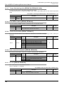
11.1 Positioning Parameters ............................................................................................................. 118
11.1.1 Operation parameters 1 [BFM #14000, BFM #14200] .............................................................. 118
11.1.2 Operation parameters 2 [BFM #14002, BFM #14202] .............................................................. 120
11.1.3 Pulse rate [BFM #14005, #14004, BFM #14205, #14204] ........................................................ 121
11.1.4 Feed rate [BFM #14007, #14006, BFM #14207, #14206] ......................................................... 121
11.1.5 Maximum speed [BFM #14009, #14008, BFM #14209, #14208] .............................................. 121
11.1.6 JOG speed [BFM #14013, #14012, BFM #14213, #14212] ...................................................... 122
11.1.7 JOG Instruction evaluation time [BFM #14014, BFM #14214] .................................................. 122
11.1.8 Acceleration time [BFM #14018, BFM #14218]......................................................................... 122
11.1.9 Deceleration time [BFM #14020, BFM #14220] ........................................................................ 123
11.1.10 Interpolation time constant [BFM #14022, BFM #14222] ........................................................ 123
11.1.11 Zero return speed (High Speed) [BFM #14025, #14024, BFM #14225, #14224].................... 123
11.1.12 Zero return speed (Creep) [BFM #14027, #14026, BFM #14227, #14226]............................. 124
11.1.13 Mechanical zero-point address [BFM #14029, #14028, BFM #14229, #14228] ..................... 124
11.1.14 Zero-phase signal count [BFM #14030, BFM #14230]............................................................ 124
11.1.15 Zero return mode [BFM #14031, BFM #14231]....................................................................... 125
11.1.16 Servo end evaluation time [BFM #14032, BFM #14232]......................................................... 125
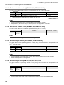
11.1.17 Software limit (upper) [BFM #14035, #14034, BFM #14235, #14234]
Software limit (lower) [BFM #14037, #14036, BFM #14237, #14236] .................................... 125
11.1.18 Torque limit [BFM #14038, BFM #14238]................................................................................ 126
11.1.19 Zero return torque limit [BFM #14040, BFM #14240] .............................................................. 126
11.1.20 External input selection [BFM #14044, BFM #14244] ............................................................. 126
11.1.21 Ring counter upper limit value [BFM #14101, #14100, BFM #14301, #14300]....................... 126
11.1.22 Sudden stop deceleration time [BFM #14102, BFM #14302].................................................. 127
11.1.23 Sudden stop interpolation time constant [BFM #14104, BFM #14304] ................................... 127
11.1.24 Positioning completion signal output waiting time [BFM #14106, BFM #14306] ..................... 127
11.2 Servo Parameters ..................................................................................................................... 128
11.2.1
11.2.2
11.2.3
11.2.4
Servo parameters (Basic settings) ............................................................................................ 128
Servo parameters (Gain/Filter settings)..................................................................................... 129
Servo parameters (Advanced setting) ....................................................................................... 131
Servo parameters (I/O setting) .................................................................................................. 133
11.3 Monitor Data.............................................................................................................................. 135
11.3.1 Current address (User) [BFM #1, #0, BFM #101, #100]............................................................ 135
11.3.2 Current address (Pulse) [BFM #3, #2, BFM #103, #102] .......................................................... 135
11.3.3 Torque limit storing value [BFM #5, #4, BFM #105, #104] ........................................................ 136
11.3.4 Error BFM numbers [BFM #6, BFM #106]................................................................................. 136
11.3.5 Terminal Information [BFM #7, BFM #107] ............................................................................... 136
11.3.6 Servo terminal information [BFM #8, BFM #108] ...................................................................... 136
11.3.7 m code [BFM #9, BFM #109]..................................................................................................... 136
11.3.8 Current value of operation speed [BFM #11, #10, BFM #111, #110] ........................................ 137
11.3.9 Current pulses input by manual pulse generator [BFM #13, #12, BFM #113, #112]................. 137
11.3.10 Frequency of pulses input by manual pulse generator [BFM #15, #14, BFM #115, #114]...... 137
11.3.11 Table numbers in execution [BFM #16, BFM #116] ................................................................ 137
11.3.12 Version information [BFM #17] ................................................................................................ 137
11.3.13 Real current address (User) [BFM #21, #20, BFM #121, #120] .............................................. 138
11.3.14 Real current address (Pulse) [BFM #23, #22, BFM #123, #122]............................................. 138
11.3.15 Received target address [BFM #25, #24, BFM #125, #124] ................................................... 138
11.3.16 Received target speed [BFM #27, #26, BFM #127, #126] ...................................................... 138
11.3.17 Status information [BFM #28, BFM #128] ............................................................................... 139
11.3.18 Error code [BFM #29, BFM #129]............................................................................................ 140
11.3.19 Model code [BFM #30] ............................................................................................................ 141
11.3.20 Status information 2 [BFM #32, BFM #132] ........................................................................... 141
11.3.21 Deviation counter value [BFM #51, #50, BFM #151, #150]..................................................... 141
11.3.22 Motor speed [BFM #53, #52, BFM #153, #152] ...................................................................... 141
11.3.23 Motor current value [BFM #54, BFM #154] ............................................................................. 141
11.3.24 Servo amplifier software number [BFM #61 to #56, BFM #161 to #156]................................. 142
11.3.25 Servo parameter error numbers [BFM #62, BFM #162] .......................................................... 143
11.3.26 Servo status [BFM #64, #63, BFM #164, #163] ...................................................................... 143
11.3.27 Regenerative load ratio [BFM #65, BFM #165] ....................................................................... 144
11.3.28 Effective load torque [BFM #66, BFM #166]............................................................................ 144
11.3.29 Peak torque ratio [BFM #67, BFM #167] ................................................................................. 144
6
FX3U-20SSC-H Positioning Block User's Manual
11.3.30
11.3.31
11.3.32
11.3.33
Table of Contents
Servo warning code [BFM #68, BFM #168]............................................................................. 144
Motor feedback position [BFM #71, #70, BFM #171, #170] .................................................... 144
Servo status 2 [BFM #72, BFM #172] ..................................................................................... 145
Flash memory write count [BFM #91, #90].............................................................................. 145
11.4 Control Data .............................................................................................................................. 146
11.4.1 Target address 1 [BFM #501, #500, BFM #601, #600] ............................................................. 146
11.4.2 Operation speed 1 [BFM #503, #502, BFM #603, #602]........................................................... 146
11.4.3 Target address 2 [BFM #505, #504, BFM #605, #604] ............................................................. 147
11.4.4 Operation speed 2 [BFM #507, #506, BFM #607, #606]........................................................... 147
11.4.5 Override setting [BFM #508, BFM #608] ................................................................................... 147
11.4.6 Torque output setting value [BFM #510, BFM #610]................................................................. 147
11.4.7 Speed change value [BFM #513, #512, BFM #613, #612]........................................................ 148
11.4.8 Target position change value (Address) [BFM #515, #514, BFM #615, #614].......................... 148
11.4.9 Target position change value (Speed) [BFM #517, #516, BFM #617, #616] ............................ 148
11.4.10 Operation command 1 [BFM #518, BFM #618]....................................................................... 148
11.4.11 Operation command 2 [BFM #519, BFM #619]....................................................................... 150
11.4.12 Operation pattern selection [BFM #520, BFM #620] ............................................................... 151
11.4.13 Table operation start number [BFM #521, BFM #621] ............................................................ 152
11.4.14 Control command enable/disable [BFM #522] ........................................................................ 152
11.4.15 Control command [BFM #523]................................................................................................. 152
11.4.16 Manual pulse generator input magnification (numerator)
[BFM #525, #524, BFM #625, #624]...................................................................................... 153
11.4.17 Manual pulse generator input magnification (denominator)
[BFM #527, #526, BFM #627, #626]....................................................................................... 153
11.4.18 Manual pulse generator response [BFM #528, BFM #628].................................................... 153
11.4.19 Manual pulse generator input selection [BFM #529] ............................................................... 154
11.4.20 Ring operation rotation direction for absolute address ............................................................ 154
11.5 Table Information ...................................................................................................................... 155
12. Program Example
158
12.1 Reading/Writing Buffer Memory ................................................................................................ 159
12.1.1 Assigned unit number................................................................................................................ 159
12.1.2 How to read/write from/to buffer memory .................................................................................. 159
12.2 Device Assignments.................................................................................................................. 161
12.3 Explanation of Operation........................................................................................................... 162
12.3.1
12.3.2
12.3.3
12.3.4
12.3.5
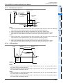
Mechanical zero return .............................................................................................................. 163
JOG operation ........................................................................................................................... 163
1-speed positioning operation ................................................................................................... 164
Multi-speed operation [table operation (individual)]................................................................... 164
Circular interpolation operation [table operation (simultaneous)] .............................................. 166
12.4 Sequence Program ................................................................................................................... 166
13. Diagnostics
173
13.1 Check LEDs .............................................................................................................................. 174
13.1.1 Check LEDs............................................................................................................................... 174
13.1.2 Input LED state indications........................................................................................................ 174
13.2 Check Error Code ..................................................................................................................... 175
13.2.1
13.2.2
13.2.3
13.2.4
Checking errors ......................................................................................................................... 175
How to reset an error................................................................................................................. 175
Error code list [BFM #29 (X-axis), BFM #129 (Y-axis)] ............................................................. 176
Servo warning list [BFM #68 (X-axis), BFM #168 (Y-axis)] ....................................................... 181
13.3 Diagnostics on the PLC Main Unit ............................................................................................ 183
13.3.1 POWER LED [on/flashing/off].................................................................................................... 183
13.3.2 BATT LED [on/off] ..................................................................................................................... 183
13.3.3 ERROR LED [on/flashing/off] .................................................................................................... 184
7
FX3U-20SSC-H Positioning Block User's Manual
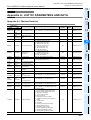
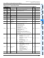
Appendix A: LIST OF PARAMETERS AND DATA
Appendix A-1
Appendix A-2
Appendix A-3
Appendix A-4
Appendix A-5
Table of Contents
185
Monitor Data List ................................................................................................ 185
Control Data Table ............................................................................................. 187
Table Information List......................................................................................... 189
Positioning parameters List ................................................................................ 191
Servo Parameters List........................................................................................ 193
Appendix B: Version Information
195
Appendix B-1 Version Information ............................................................................................ 195
Appendix B-1-1 Version check method ................................................................................................ 195
Appendix B-1-2 Version Upgrade History............................................................................................. 195
Warranty................................................................................................................................. 197
Revised History ..................................................................................................................... 198
8
FX3U-20SSC-H Positioning Block User's Manual
Certification of UL, cUL standards
Standards
Certification of UL, cUL standards
The following product has UL and cUL certification.
UL, cUL File number :E95239
Models: MELSEC FX3U series manufactured
FX3U-20SSC-H
from June 1st, 2006
Compliance with EC directive (CE Marking)
This document does not guarantee that a mechanical system including this product will comply with the
following standards.
Compliance to EMC directive and LVD directive for the entire mechanical module should be checked by the
user / manufacturer. For more details please contact the local Mitsubishi Electric sales site.
Requirement for Compliance with EMC directive
The following products have shown compliance through direct testing (of the identified standards below) and
design analysis (through the creation of a technical construction file) to the European Directive for
Electromagnetic Compatibility (89/336/EEC) when used as directed by the appropriate documentation.
Type:
Models:
Programmable Controller (Open Type Equipment)
MELSEC FX3U series manufactured
from December 1st, 2005
FX3U-20SSC-H
Standard
Remark
EN61131-2:2003
Programmable controllers
- Equipment requirements and tests
Compliance with all relevant aspects of the standard.
• Radiated Emissions
• Mains Terminal Voltage Emissions
• RF immunity
• Fast Transients
• ESD
• Conducted
• Power magnetic fields
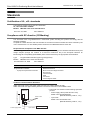
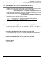
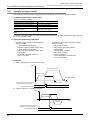
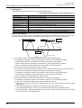
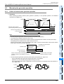
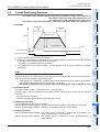
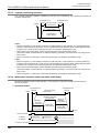
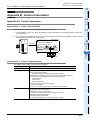
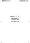
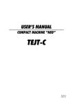
Caution to conform with EC Directives
Attach the ferrite cores to the power supply and the input cables (20SSC-H side).
Attach the ferrite core approximately 200 mm or less from connector on the 20SSC-H side.
200 mm (0.78") or less
20SSC-H
Power supply cable
Ferrite cores
• The ferrite core should use the following equivalent
product:
- Power supply cable (needs at least 1 turn)
Model name: ZCAT2035-0930
(Manufactureed by TDK co., Ltd.)
- Input cable
Model name: ZCAT3035-1330
(Manufactureed by TDK co., Ltd.)
1 turn
Input cable
External equipment
9
FX3U-20SSC-H Positioning Block User's Manual
Compliance with EC directive (CE Marking)
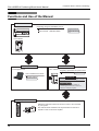
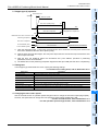
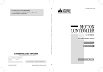
Functions and Use of the Manual
PLC
Regarding wiring and installation of PLC:
FX 3U Series
Hardware manual
Supplied Manual
User’s Manual - Hardware Edition
Additional Manual
FX 3UC Series
FX Configurator-FP
FX3U -20SSC-H
FX Configurator-FP
FX3U -20SSC-H
How to install/use the device
MOTOR-X
START
DOG
INT0
INT1
A
B
MOTOR-Y
START
DOG
INT0
INT1
A
B
X-READY
Y-READY
X-ERROR
Y-ERROR
Regarding specification and parts names
Installation Manual Supplied Manual
POWER
Operation Manual
Supplied Manual
This Manual
Operating instructions and program examples
User’s Manual
Additional Manual
Shows how to use FX3U-20SSC-H
positioning special function block and
details on example programs.
Servo amplifer, Servo motor
Obtain the instruction manual of the servo motor to be connected
to your system.
This manual will be needed to set the parameters for the servo
amplifer or write to the servo amplifer.
10
FX3U-20SSC-H Positioning Block User's Manual
Compliance with EC directive (CE Marking)
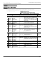
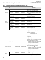
Associated Manuals
For a detailed explanation of the FX3U-20SSC-H positioning block, refer to this manual.
For the operation of FX Configurator-FP, or hardware information and instructions on the PLC main unit, refer
to the respective manuals.
~ Refer to these manuals
Refer to the appropriate equipment manual
For a detailed explanation, refer to an additional manual
Title of manual
Document
number
Description
Model code
-
Manual for the Main Module
FX3U Series PLCs Main Unit
~
Supplied
Manual
FX3U Series
Hardware Manual
JY997D18801
Describes FX3U Series PLC specification for I/O,
wiring and installation extracted from the FX3U
User’s Manual - Hardware Edition.
For details, refer to FX3U Series User’s Manual Hardware Edition.
Additional
Manual
FX3U Series
User’s Manual
- Hardware Edition
JY997D16501
Describes FX3U Series PLC specification details for
I/O, wiring, installation and maintenance.
09R516
Supplied
Manual
FX3UC Series
Hardware Manual
(Only Japanese
document)
JY997D12701
Describes FX3UC Series PLC specification for I/O,
wiring and installation extracted from the FX3UC
User’s Manual - Hardware Edition.
For details, refer to FX3UC Series User’s Manual Hardware Edition (Only
Japanese document).
-
Additional
Manual
FX3UC Series
User’s Manual
- Hardware Edition
(Only Japanese
document)
JY997D11601
Describes FX3UC Series PLC specification details
for I/O, wiring, installation and maintenance.
(Only Japanese document)
09R513
JY997D16601
Describes FX3U / FX3UC Series PLC
programming for basic/ applied
instructions and devices.
09R517
FX3UC Series PLCs Main Unit
~
Programming for FX3U/FX3UC Series
~
Additional
Manual
FX3U / FX3UC Series
Programming Manual
- Basic & Applied
Instruction Edition
Manuals for FX3U-20SSC-H Positioning Block
Supplied
Manual
FX3U-20SSC-H
Installation Manual
JY997D21101
Describes FX3U-20SSC-H positioning block
specification for I/O, power supply extracted from
the FX3U-20SSC-H User’s Manual.
For details, refer to FX3U-20SSC-H User's Manual.
-
~
Additional
Manual
FX3U-20SSC-H
User's Manual
JY997D21301
Describes FX3U-20SSC-H Positioning block details.
09R622
~
Supplied
Manual
FX Configurator-FP
Operation Manual
JY997D21801
Describes operation details of FX Configurator-FP
Configuration Software.
09R916
SH-030051
Explains parameters and the detailed specifications
for MR-J3- B servo amplifier.
-
IB67339
Explains installation procedures to conform with
EMC Directives and fabrication method of control
board.
-
AC Servo Related Manual
Additional
Manual
MR-J3- B
Instruction Manual
Additional
Manual
EMC
Installation Guidelines
11
FX3U-20SSC-H Positioning Block User's Manual
Compliance with EC directive (CE Marking)
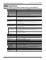
Generic Names and Abbreviations Used in the Manual
Generic name or abbreviation
Description
PLC
FX3U series
FX3U PLC or main unit
FX3UC series
FX3UC PLC or main unit
Generic name for FX3U Series PLC
Generic name for FX3U Series PLC main unit
Generic name for FX3UC Series PLC
Generic name for FX3UC Series PLC main unit
Only manuals in Japanese are available for these products.
Expansion board
Expansion board
Generic name for expansion board
The number of connectable units, however, depends on the type of main unit.
To check the number of connectable units, refer to the User's Manual - Hardware Editon of the main
unit to be used for your system.
Special adapter
Special adapter
Generic name for high-speed input/output special adapter, communication special adapter, and
analog special adapter
The number of connectable units, however, depends on the type of main unit.
To check the number of connectable units, refer to the User's Manual - Hardware Editon of the main
unit to be used for your system.
Special function unit/block
Special function unit/block or
Special extension unit
Generic name for special function unit and special function block
The number of connectable units, however, depends on the type of main unit.
To check the number of connectable units, refer to the User's Manual - Hardware Edition of the main
unit to be used for your system.
Special function unit
Generic name for special function unit
Special function block
Generic name for special function block
The number of connectable units, however, depends on the type of main unit.
To check the number of connectable units, refer to the User's Manual - Hardware Edition of the main
unit to be used for your system.
Positioning special function
block
Abbreviated name for FX3U-20SSC-H
or 20SSC-H
Optional unit
Memory cassette
FX3U-FLROM-16, FX3U-FLROM-64, FX3U-FLROM-64L
Battery
FX3U-32BL
FX Series terminal block
FX-16E-TB, FX-32E-TB
Input/output cable
or Input cable
FX-16E-500CAB-S, FX-16E-
CAB, FX-16E-
CAB-R
represents 150, 300, or 500.
Input/output connector
FX2C-I/O-CON, FX2C-I/O-CON-S, FX2C-I/O-CON-SA
Power cable
FX2NC-100MPCB, FX2NC-100BPCB, FX2NC-10BPCB1
Peripheral unit
Peripheral unit
Generic name for programming software, handy programming panel, and indicator
Programming tool
Programming tool
Generic name for programming software and handy programming panel
Programming software
Generic name for programming software
GX Developer
Generic name for SW
FX-PCS/WIN(-E)
Generic name for FX-PCS/WIN or FX-PCS/WIN-E programming software package
Handy programming panel (HPP)
D5C-GPPW-J/SW
D5C-GPPW-E programming software package
Generic name for FX-20P(-E) and FX-10P(-E)
Configuration software
Configuration software or
FX Configurator-FP
12
Abbreviated name for FX Configurator-FP Configuration software
FX3U-20SSC-H Positioning Block User's Manual
Generic name or abbreviation
Compliance with EC directive (CE Marking)
Description
Indicator
GOT1000 series
Generic name for GT15, GT11 and GT10
GOT-900 series
Generic name for GOT-A900 series and GOT-F900 series
GOT-A900 series
Generic name for GOT-A900 series
GOT-F900 series
Generic name for GOT-F900 series
ET-940 series
Generic name for ET-940 series
Only manuals in Japanese are available for these products
Servo motor/servo amplifier
Servo motor
Generic name for servo motor or stepping motor
Including servo amplifier corresponding to SSCNET III.
Servo amplifier
Generic name for servo amplifier corresponding to SSCNET III
MELSERVO series
Generic name for MELSERVO-J3 series
Other unit
Manual pulse generator
Generic name for manual pulse generator (prepared by user)
Manual
FX3U hardware Edition
FX3U Series User's Manual - Hardware Edition
FX3UC hardware Edition
This manual is only available in Japanese.
Programming manual
FX3U/FX3UC Series Programming Manual - Basic and Applied Instructions Edition
Communication control Edition
FX Series User's Manual - Data Communication Edition
Analog control Edition
FX3U/FX3UC Series User's Manual - Analog Control Edition
Positioning control Edition
FX3U/FX3UC Series User's Manual - Positioning Control Edition
13
FX3U-20SSC-H Positioning Block User's Manual
Compliance with EC directive (CE Marking)
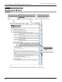
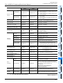
Reading the Manual
Shows the manual title.
This area shows the
manual title for the current
page.
Shows the title of the chapter and the title
Indexes the chapter number.
of the section.
The right side of each page
indexes the chapter number
for the page currently opened.
This area shows the title of the chapter and the
title of the section for the current page.
Shows the reference.
The " " mark indicates
a reference destination
and reference manual.
The above is different from the actual page, as it is provided for explanation only.
14
1 Introduction
FX3U-20SSC-H Positioning Block User's Manual
1.1 Outline
1
Introduction
2
Outline
The FX3U-20SSC-H type positioning block (hereinafter referred to as 20SSC-H) is a special function block
applicable to SSCNET III.
20SSC-H can perform positioning control by servo motor via an SSCNET III applied servo amplifier.
One 20SSC-H controls 2 axes.
20SSC-H applies the 1-speed positioning and interrupt 1-speed constant quantity feed operations for
constant quantity feed control, and also the linear interpolation and circular interpolation operations.
→ For positioning control, refer to Chapter 9.
2. Connection to servo amplifier by SSCNET III is possible
• Connection using the SSCNET III cable between the 20SSC-H and the servo amplifier reduces wiring.
(Maximum length is 50m.)
• With SSCNET III cables (optical communication), connections are less susceptible to electromagnetic
noise, etc. from the servo amplifier.
• Current values and error descriptions from the servo amplifier can be checked with the buffer memories of
the 20SSC-H.
3. Easy application of absolute position detection system
• Once the zero position is established, the zero return operation at power startup is not necessary.
• The absolute position system allows establishment of the zero position by the data set type zero return.
In this case, wiring for near-point DOG, etc. is not required.
4. Easy maintenance
5. Connectable PLC
• The connected FX3U or FX3UC PLC reads/writes the positioning data from/to the 20SSC-H.
7
Before starting
positioning
control
Various data such as positioning data, parameters, etc. can be saved to the flash memory (ROM) in the
20SSC-H.
This allows the data to be saved without a battery.
6
Memory
configuration
and data
• The servo amplifier with absolute position detection enables the absolute positioning detection system.
5
Wiring
• Setting the servo parameters on the 20SSC-H side and writing/reading the servo parameters to/from the
servo amplifier using SSCNET III is possible.
4
Installation
The 20SSC-H connects directly to the MELSERVO (our company's servo amplifier: MR-J3-B) via SSCNETIII.
3
Exmample
Connection
1. 2-axis control is possible
System
configuration
1.1
Introduction
1.
8
Manual control
• For connection to the FX3UC PLC, the FX2NC-CNV-IF or FX3UC-1PS-5V is needed.
9
Positioning
Control
10
Table Operation
15
1 Introduction
FX3U-20SSC-H Positioning Block User's Manual
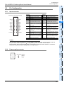
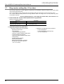
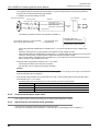
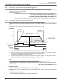
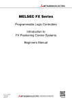
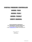
1.2
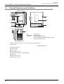
1.2 External Dimensions and Part Names
External Dimensions and Part Names
INT0
INT1
A
B
[2]
MOTOR-Y
START
DOG
INT0
INT1
A
B
X-READY
Y-READY
X-ERROR
Y-ERROR
[3]
POWER
[4]
[5]
90(3.55")
[1]
80(3.15") (Mounting hole pitch)
2 - 4.5 Mounting hole
[7]
[8]
4(0.16")
9(0.36")
87(3.43")
55(2.17")
[9]
[6]
[10]
Unit:
mm (inches)
MASS(Weight): 0.3kg (0.66 lbs)
Accessory:
- Special Unit/Block No. label
- FX2NC-100MPCB Power supply cable [1m (3’3")]
- Dust proof protection sheet
[1] Direct mounting hole:2 holes of φ 4.5 (0.18") (mounting screw: M4 screw)
[2] Status LEDs
→ Refer to Section 1.3
[3] POWER LED (green)
[4] Extension cable
[5] Input connector
[6] Power supply connector
[7] DIN rail mounting groove (DIN rail: DIN46277)
[8] Name plate
[9] DIN rail mounting hook
[10] SSCNET III connector
16
1 Introduction
FX3U-20SSC-H Positioning Block User's Manual
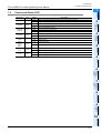
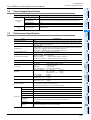
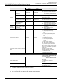
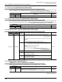
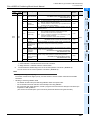
1
Power and Status LED
LED display
POWER
Green
Green
X-START
Y-START
Red
X-DOG
Y-DOG
Red
X-INT0
Y-INT0
X-INT1
Y-INT1
Red
X- φ A
Y- φ A
Red
X- φ B
Y- φ B
Red
Power is not being supplied from the external power supply or the PLC
ON
Power is being supplied from the external power supply or the PLC
OFF
Error is occurring or positioning is being executed on the X/Y axis
ON
Various operation commands are acceptable on the X/Y axis
OFF
X/Y axis is operating normally
Flicker
ON
2
Error is occurring on the X/Y axis
CPU error is occurring on the X/Y axis
OFF
Start input OFF
ON
Start input ON
OFF
DOG input OFF
ON
DOG input ON
OFF
Interrupt input OFF
ON
Interrupt input ON
OFF
Manual pulse generator A-phase input OFF
ON
Manual pulse generator A-phase input ON
OFF
Manual pulse generator B-phase input OFF
ON
Manual pulse generator B-phase input ON
3
4
Installation
Red
Description
OFF
Exmample
Connection
X-ERROR
Y-ERROR
Status
System
configuration
X-READY
Y-READY
Color
Introduction
1.3
1.3 Power and Status LED
5
Wiring
6
Memory
configuration
and data
7
Before starting
positioning
control
8
Manual control
9
Positioning
Control
10
Table Operation
17
2 System Configuration
FX3U-20SSC-H Positioning Block User's Manual
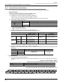
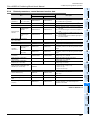
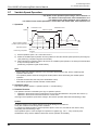
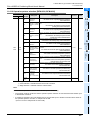
2.
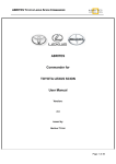
2.1 General Configuration
System Configuration
2.1
General Configuration
GX Developer
FX Configurator-FP
(PC)
20SSC-H
FX 3U / FX 3UC
PLC
Monitor data
Control data
SSCNET III cable
USB cable
RS-232C cable
Ladder
FROM/TO
instruction, etc.
Positioning parameter
Table information
FX-16E-150CAB(-R)
Upper limit signal
Lower limit signal
Emergency stop input signal
Servo amplifier
Connector-attached
flat cable for connecting
terminal block with FX
programmable logic controller
LS for forward
rotation limit
(X-axis, Y-axis)
Emergency stop input signal
Servo amplifier
(MR-J3-B)
Servo parameter
Upper limit signal
(MR-J3-B)
Lower limit signal
FX-16E-TB
Terminal block
LS for reverse
rotation limit
(X-axis, Y-axis)
START input (X-axis, Y-axis)
DOG input (X-axis, Y-axis)
Interrupt input (X-axis, Y-axis)
Manual pulse generator A/B-phase
division input (X-axis, Y-axis)
STOP switch
(X-axis, Y-axis)
MR Configurator(PC)
Component list
Part name
Model name
Positioning block
FX3U-20SSC-H
PLC
FX3U/FX3UC PLC
Remarks
-
GX Developer
PLC programming software
PC software
FX Configurator-FP
Setting/Monitoring software for setting or monitoring the
servo parameters, positioning parameters and table
information
MR Configurator
Servo amplifier set-up software
PC
DOS/V
USB cable
FX-USB-AW
Connection cable between FX PLC and PC
F2-232CAB-1
RS-232C cable
FX-232AWC-H
PC connection cable and interface
FX-422CAB0
Servo amplifier
MR-J3-
-
B
Inside panel standard code : MR-J3BUS
SSCNET III cable
Outside panel standard cable : MR-J3BUS
Long distance cable : MR-J3BUS
Terminal block
I/O cable
18
FX-16E-TB
FX-16E-
CAB
FX-16E-
CAB-R
M-B
M
: 015/03/05/1/3(Cable length: in meters)
M-A
: 5/10/20(Cable length:in meters)
: 30/40/50(Cable length:in meters)
: 150/300/500
Cable length 150:1.5m, 300:3m, 500:5m
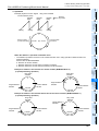
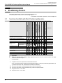
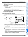
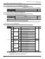
2 System Configuration
FX3U-20SSC-H Positioning Block User's Manual
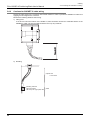
1
Connection with PLC
FX3U-20SSC-H FX3U-20SSC-H
FX3U Series PLC
MOTOR-Y
START
DOG
INT0
INT1
A
B
MOTOR-X
START
DOG
INT0
INT1
A
B
X-READY
Y-READY
X-ERROR
Y-ERROR
POWER
MOTOR-Y
START
DOG
INT0
INT1
A
B
3
X-READY
Y-READY
X-ERROR
Y-ERROR
Example
Connection
MOTOR-X
START
DOG
INT0
INT1
A
B
2
System
configuration
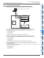
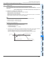
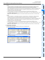
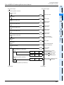
20SSC-H connects with PLC via extension cable.
The 20SSC-H is handled as a special extension block of the PLC. The unit number of the 20SSC-H is
automatically assigned No.0 to No.7 starting from the special function unit/block closest to the PLC main unit.
(This unit number is used for the designation of a FROM/TO instruction.) For details on assignment of the I/O
number and unit number of the PLC, refer to the following manual corresponding to the connected PLC.
→ FX3U Hardware Edition
→ FX3UC Hardware Edition (Japanese document only)
Introduction
2.2
2.2 Connection with PLC
POWER
4
Installation
FX3UC Series PLC FX3U-20SSC-H
MOTOR-X
START
DOG
INT0
INT1
A
B
MOTOR-Y
START
DOG
INT0
INT1
A
B
X-READY
Y-READY
X-ERROR
Y-ERROR
POWER
MOTOR-X
START
DOG
INT0
INT1
A
B
MOTOR-Y
START
DOG
INT0
INT1
A
B
X-READY
Y-READY
X-ERROR
Y-ERROR
POWER
5
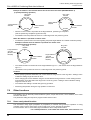
Wiring
FX2NC-CNV-IF
FX3U-20SSC-H
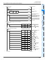
• An FX2NC-CNV-IF or FX3UC-1PS-5V is necessary to connect the 20SSC-H with the FX3UC PLC.
• The optional FX0N-65EC (FX0N-30EC) and FX2N-CNV -BC are necessary to lengthen the extension cable.
8
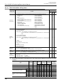
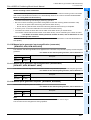
Applicable PLC
Model name
Manual control
2.3
Applicability
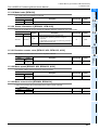
FX3UC Series PLC*1
Ver. 2.20 (from products manufactured in May, 2005 with SER No. 55****) and later
Up to 7 blocks can be connected
9
Positioning
Control
FX3U Series PLC
Ver. 2.20 (from the first product) and later
Up to 8 blocks can be connected
The version number can be checked by monitoring the last three digits of D8001.
*1.
7
Before starting
positioning
control
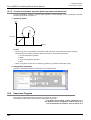
• The number of I/O points occupied by the 20SSC-H is eight. Be sure that the total of the number of I/O
points (occupied I/O points) of the main unit, power extension unit and extension block and the number of
points occupied by the special function block does not exceed the maximum number of I/O points of the
PLC.
For the maximum number of I/O points of the PLC, refer to the following manual.
→ FX3U Hardware Edition
→ FX3UC Hardware Edition (Japanese document only)
6
Memory
configuration
and data
• A maximum of 8 units/blocks can be connected with the FX3U PLC. With the FX3UC PLC, a maximum of 7
units/blocks can be connected.
An FX2NC-CNV-IF or FX3UC-1PS-5V is necessary to connect the 20SSC-H with the FX3UC PLC.
10
Table Operation
19
3 Specifications
FX3U-20SSC-H Positioning Block User's Manual
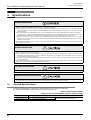
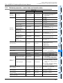
3.
3.1 General Specifications
Specifications
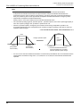
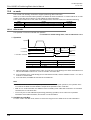
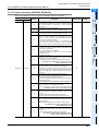
DESIGN PRECAUTIONS
•
•
Make sure to have the following safety circuits outside of the PLC to ensure safe system operation even during external power supply
problems or PLC failure. Otherwise, malfunctions may cause serious accidents.
1) Most importantly, have the following: an emergency stop circuit, a protection circuit, an interlock circuit for opposite movements
(such as normal vs. reverse rotation), and an interlock circuit (to prevent damage to the equipment at the upper and lower
positioning limits).
2) Note that when the PLC CPU detects an error, such as a watchdog timer error, during self-diagnosis, all outputs are turned off.
Also, when an error that cannot be detected by the PLC CPU occurs in an input/output control block, output control may be
disabled. External circuits and mechanisms should be designed to ensure safe machinery operation in such a case.
3) Note that when an error occurs in a relay, triac or transistor output device, the output could be held either on or off. For output
signals that may lead to serious accidents, external circuits and mechanisms should be designed to ensure safe machinery
operation in such a case.
At Forward/Reverse rotation limits, make sure to wire the contacts with NC, negative-logic. Wiring contacts with NO, positive-logic
may cause serious accidents.
DESIGN PRECAUTIONS
•
•
Make sure to observe the following precautions in order to prevent any damage to the machinery or accidents due to abnormal data
written to the PLC under the influence of noise:
1) Do not bundle the main circuit line together with or lay it close to the main circuit, high-voltage line or load line. Otherwise, noise
disturbance and/or surge induction are likely to take place. As a guideline, lay the control line at least 100mm (3.94") or more away
from the main circuit or high-voltage lines.
2) Ground the shield wire or shield of the shielded cable at one point on the PLC. However, do not ground them at the same point as
the high-voltage lines.
Install module so that excessive force will not be applied to the built-in programming connectors, power connectors or I/O connectors.
Failure to do so may result in wire damage/breakage or PLC failure.
DISPOSAL PRECAUTIONS
•
Please contact a certified electronic waste disposal company for the environmentally safe recycling and disposal of your device.
TRANSPORTATION PRECAUTIONS
•
3.1
The PLC is a precision instrument. During transportation, avoid impacts larger than those specified in the manual of the PLC main
unit. Failure to do so may cause failures in the PLC. After transportation, verify the operations of the PLC.
General Specifications
For items not listed below, specifications are equivalent to those of the PLC main unit.
For general specifications, refer to the manual of the PLC main unit.
→ Refer to FX3U Hardware Edition
→ Refer to FX3UC Hardware Edition (Japanese document only)
Item
Specification
Dielectric withstand voltage 500V AC for one minute
Insulation resistance
20
5MΩ or more by 500V DC Megger
Conforming to JEM-1021
Between all terminals and ground terminal
3 Specifications
FX3U-20SSC-H Positioning Block User's Manual
1
Power Supply Specification
Item
Internal power
supply
Specification
Power supply voltage
24V DC +20% -15% Ripple (p-p) within 5%
Permitted instantaneous
power failure time
Operation continues when the instantaneous power failure is shorter than 5ms.
Powerconsumption
5W
Power fuse
1A
PLC power supply
100mA /5V DC
2
System
configuration
External power
supply
Introduction
3.2
3.2 Power Supply Specification
3
Example
Connection
3.3
Performance Specification
Item
Specification
Backup
Applicable PLC
FX3U/FX3UC PLC
An FX2NC-CNV-IF or FX3UC-1PS-5V is necessary to connect the 20SSC-H with the FX3UC PLC.
A maximum of 8 units/blocks can be connected with the FX3U PLC.
A maximum of 7 units/blocks can be connected with the FX3UC PLC.
No. of occupied I/O points
8 points (input or output, whichever may be counted)
Connectable servo amplifier
MELSERVO MR-J3- B
Maximum 2 amplifiers can be connected
Standard cord length
: Station to station maximum 20m (65’7")
Long distance cord length : Station to station maximum 50m (164’)
SSCNET III
Scan cycle
1.77ms
Control input
Interrupt input
DOG
START input
Manual pulse generator
: 2 inputs (INT0 and INT1) per axis
: 1 input per input axis
: 1 input per axis
: 1 input per axis (A/B-phase)
Positioning parameter
Servo parameter
: Ver. 1.20 or later
Ver. 1.10 or later
Earlier than Ver. 1.10
: 50 types
Control data
Ver. 1.10 or later
Earlier than Ver. 1.10
: 20 types
: 17 types
Monitor data
Ver. 1.20 or later
Earlier than Ver. 1.20
: 31 types
: 26 types
Positioning program
Created by sequence programs (using FROM/TO instruction, etc.)
Direct operation (1 for X and Y axes respectively)
Table operation (300 tables for X, Y, and XY axes respectively)
Parameter
Unit
PLS,µm, 10-4inch, mdeg
Unit magnification
1, 10, 100, and 1000-fold
25 types
22 types
21 types
-2,147,483,648 to 2,147,483,647 PLS
Speed command
Hz, cm/min, inch/min, 10deg/min
Acceleration/
deceleration
process
Trapezoidal acceleration/deceleration, S-pattern acceleration/deceleration: 1 to 5,000ms
Only trapezoidal acceleration/deceleration is available for interpolation
Starting time
1.6ms or less
Interpolation
function
2-axes linear interpolation, 2-axes circular interpolation
8
9
Positioning
Control
Positioning range
7
Manual control
Increment/Absolute
6
Before starting
positioning
control
Positioning
Method
5
Memory
configuration
and data
Servo bus
4
Wiring
2 axes
Positioning parameters, servo parameters, and table information can be saved to flash memory
Write count: Maximum 100,000 times
Installation
Number of control axes
10
Table Operation
21
3 Specifications
FX3U-20SSC-H Positioning Block User's Manual
3.4
Input Specifications
3.4.1
Input specifications
Item
3.4 Input Specifications
Specification
X axis interrupt input: X-INT0, X-INT1
Used for interrupt operation
Y axis interrupt input: Y-INT0, Y-INT1
Used for interrupt operation
Group 1
X axis near-point DOG input: X-DOG
Used for zero return
Y axis near-point DOG input: Y-DOG
Used for zero return
START command for X axis positioning operation: X-START
Input signal name
START command for Y axis positioning operation: Y-START
Group 2
Group 3
Group 1
Group 2
Group 3
3.4.2
Manual pulse generator input for X axis:
X- φ A+/X- φ A-, X- φ B+/X- φ B1 edge count at 2-phase 2-count
Manual pulse generator input for Y axis:
Y- φ A+/Y- φ A-, Y- φ B+/Y- φ B1 edge count at 2-phase 2-count
External power supply for signals: S/S
Connected to power supply for INT0, INT1, DOG and START
Operation display
LED ON at input ON
Signal voltage
24V DC +20% -15% (Power is supplied from S/S terminal)
Input current
7.0mA ± 1mA /24V DC
ON current
4.5mA or more
OFF current
1.5mA or less
Signal form
No-voltage contact input
Sink input: NPN open collector transistor
Source input: PNP open collector transistor
Response time
Hardware filter 1ms or less
Circuit insulation
Photo-coupler insulation
Operation display
LED ON at input ON
Signal voltage
3 to 5.25V DC
Input current
3.0 to 8.5mA
ON current
3.0mA or more
OFF current
0.5mA or less
Signal form
Differential line driver
(corresponding to AM26LS31)
Response
frequency
2-phases pulse 100KHz or less (Duty 50%)
Circuit insulation
Photo-coupler insulation
Power supply
voltage
24V DC +20% -15%
Consumption
current
64mA or less
Internal input circuit
For the internal input circuit diagram, refer to the following.
→ For the internal input circuit diagram, refer to section 5.3
22
3 Specifications
FX3U-20SSC-H Positioning Block User's Manual
Pin Configuration
3.5.1
Input connector
1
Introduction
3.5
X-
A+
Y-
A+
X-
A-
Y-
A-
X-
B+
Y-
B+
X-
B-
Y-
B-
Y-DOG
X-DOG
Interrupt input (for X axis)
Y-INT0
Interrupt input (for Y axis)
NC
Not used
NC
Not used
X-INT1
Interrupt input (for X axis)
Y-INT1
X- φ A+
Input terminal for A-phase input
Y- φ A+
of 2-phase pulse (for X axis)
Input terminal for A-phase input
of 2-phase pulse (for Y axis)
3
X- φ A-
Common terminal for
A-phase input of 2-phase pulse Y- φ A(for X axis)
Common terminal for
A-phase input of 2-phase pulse
(for Y axis)
X- φ B+
Input terminal for B-phase input
Y- φ B+
of 2-phase pulse (for X axis)
Input terminal for B-phase input
of 2-phase pulse (for Y axis)
X- φ B-
Common terminal for
B-phase input of 2-phase pulse Y- φ B(for X axis)
Common terminal for
B-phase input of 2-phase pulse
(for Y axis)
X-DOG
Near-point DOG input terminal
Y-DOG
(for X axis)
Near-point DOG input terminal
(for Y axis)
S/S
Power input terminal (START,
DOG, INT0 and INT1) 24VDC
S/S
Pins that have the same name
(S/S) are shorted inside.
Power input terminal (START,
DOG, INT0 and INT1) 24VDC
Pins that have the same name
(S/S) are shorted inside.
5
S/S
S/S
Y-START
X-START
Description
X-INT0
Y-INT1
X-INT1
2
Terminal
name
Installation
NC
NC
Description
Example
Connection
Y-INT0
Terminal
name
System
configuration
Connector pin array (aperture side)
X-INT0
3.5 Pin Configuration
START input terminal (for Y axis)
Caution
The pin array is seen from the connection side (aperture side) of the input connectors of the 20SSC-H.
The pin numbers and the position of
vary depending on the connectors for user cables.
Perform proper wiring while paying attention to the position of notches and the direction of connectors.
Otherwise, the product may be damaged due to wiring mistakes.
6
Memory
configuration
and data
3.5.2
4
Wiring
X-START START input terminal (for X axis) Y-START
Interrupt input (for Y axis)
Power supply connector
7
Before starting
positioning
control
3 Grounding (Green)
2
−
(Black)
1
+
(Red)
8
Manual control
9
Positioning
Control
10
Table Operation
23
4 Installation
FX3U-20SSC-H Positioning Block User's Manual
4.
Installation
INSTALLATION PRECAUTIONS
•
Make sure to cut off all phases of the power supply externally before attempting installation or wiring work. Failure to do so may cause
electric shock.
INSTALLATION PRECAUTIONS
•
•
•
•
•
•
•
•
Connect the extension cables, peripheral device cables, input/output cables and battery connecting cable securely to their designated
connectors. Unsecured connection may cause malfunctions.
Use the product within the generic environment specifications described in section 3.1 of this manual.Never use the product in areas
with excessive dust, oily smoke, conductive dusts, corrosive gas (salt air, Cl2, H2S, SO2 or NO2), flammable gas, vibration or
impacts, or exposed to high temperature, condensation, or rain and wind. If the product is used in such conditions, electric shock, fire,
malfunctions, deterioration or damage may occur.
Do not touch the conductive parts of the product directly to avoid failure or malfunctions.
Install the product securely using a DIN rail or mounting screws.
Install the product on a flat surface.If the mounting surface is rough, undue force will be applied to the PC board, thereby causing
nonconformities.
When drilling screw holes or wiring, make sure cutting or wiring debris does not enter the ventilation slits. Failure to do so may cause
fire, equipment failures or malfunctions.
Be sure to remove the dust proof sheet from the PLC's ventilation port when installation work is completed. Failure to do so may
cause fire, equipment failures or malfunctions.
Make sure to attach the terminal cover, offered as an accessory, before turning on the power or initiating operation after installation or
wiring work. Failure to do so may cause electric shock.
The product can be connected on the right side of the main unit or extension unit/block. To connect to the
FX3UC PLC or FX2NC PLC extension block, the FX2NC-CNV-IF or FX3UC-1PS-5V is necessary. For the
installation environment, refer to the following respective manual.
→ Refer to the FX3U Hardware Edition
→ Refer to the FX3UC Hardware Edition (Japanese document only)
20SSC-H may be installed in a control cabinet with a 35 mm wide DIN46277 DIN rail mounting or M4 screw
direct mounting.
24
4 Installation
FX3U-20SSC-H Positioning Block User's Manual
1
DIN rail Mounting
Introduction
4.1
4.1 DIN rail Mounting
The product may be mounted on a 35mm wide DIN46277 (DIN rail).
1
1
Push the product onto the DIN rail.
2
System
configuration
2
Fit the upper edge (A in the figure to the right) of the DIN
rail mounting groove onto the DIN rail.
A
• An interval space between each unit of 1 to 2 mm (0.04" to 0.08") is
necessary.
Connect the extension cable.
Example
Connection
3
3
2
Connect the extension cable (B in the figure to the right) to
the main unit, I/O extension unit/block or special function
unit/block on the left side of the product.
For the extension cable connection procedure, refer to the
following respective PLC manual.
B
4
Installation
→ Refer to the FX3U Hardware Edition
→ Refer to the FX3UC Hardware Edition
(Japanese document only)
5
Wiring
4.2
Direct Mounting
1
7
Before starting
positioning
control
2
Make mounting holes in the mounting surface
according to the external dimensions
diagram.
Fit 20SSC-H (A in the figure to the right) to
holes and tighten M4 screws (B in the figure
to the right).
8
FX
3U
-48
M
10
Connect the extension cable.
2
12
3
13
4
14
5
15
0
10
1
11
2
12
3
6
16
7
17
20
21
13
4
14
5
15
6
16
7
22
17
20
21
22
23
24
25
26
PO
27
PO
WER
WER
RURU
N N
BA BA
TT TT
ERER
RORO
R R
23
24
25
26
27
B
9
Positioning
Control
Connect the extension cable to the main unit, I/O extension unit/block or special function unit/block on the left side
of the product.
(Refer to Step 3 in Section 4.1.)
For extension cable connection procedure, refer to the following respective PLC manual.
1
11
OU
T
→ For dimensions, refer to Section 1.2.
3
IN 0
Manual control
For the screw position and quantity, refer to the dimensioned drawing specified below.
6
Memory
configuration
and data
The product can be installed directly with screws.
An interval space between each unit of 1 to 2 mm (0.04" to 0.08") is necessary.
For installation, refer to the following respective PLC manual.
→ For mounting hole pitches, refer to Section 1.2.
→ Refer to the FX3U Hardware Edition
→ Refer to the FX3UC Hardware Edition (Japanese document only)
A
B
10
Table Operation
→ Refer to the FX3U Hardware Edition
→ Refer to the FX3UC Hardware Edition
(Japanese document only)
25
5 Wiring
FX3U-20SSC-H Positioning Block User's Manual
5.
Wiring
DESIGN PRECAUTIONS
•
•
Make sure to observe the following precautions in order to prevent any damage to the machinery or accidents due to abnormal data
written to the PLC under the influence of noise:
1) Do not bundle the main circuit line together with or lay it close to the main circuit, high-voltage line or load line. Otherwise, noise
disturbance and/or surge induction are likely to take place. As a guideline, lay the control line at least 100mm (3.94") or more away
from the main circuit or high-voltage lines.
2) Ground the shield wire or shield of the shielded cable at one point on the PLC. However, do not ground them at the same point as
the high-voltage lines
Install module so that excessive force will not be applied to the built-in programming connectors, power connectors or I/O connectors.
Failure to do so may result in wire damage/breakage or PLC failure.
WIRING PRECAUTIONS
•
Make sure to cut off all phases of the power supply externally before attempting installation or wiring work. Failure to do so may cause
electric shock.
WIRING PRECAUTIONS
•
•
•
•
•
•
•
•
•
•
•
•
•
•
26
Use class D grounding (grounding resistance of 100Ω or less) with wire as thick as possible on the grounding terminal of the 20SSCH. However, do not connect the ground terminal at the same point as a heavy electrical system.
Make sure to attach the terminal cover, offered as an accessory, before turning on the power or initiating operation after installation or
wiring work. Failure to do so may cause electric shock.
Make sure to connect cables and wires to the power/signal inputs of the 20SSC-H as described in this manual. Connecting AC power
cables with DC power sources or DC I/O terminals will burn out the hardware components.
Do not wire vacant terminals externally. Doing so may damage the product.
When drilling screw holes or wiring, make sure cutting or wiring debris does not enter the ventilation slits.Failure to do so may cause
fire, equipment failures or malfunctions.
Make sure to properly wire the FX Series terminal blocks in accordance with the precautions below in order to prevent electric shock,
a short-circuit, wire breakage, or damage to the product.
- The disposal size of the cable end should follow the dimensions described in this manual.
- Tightening torque should be between 0.5 and 0.8 N•m.
Do not wire or bundle the SSCNET III cables together with or lay them near a main circuit cable, high-voltage line, or load lines
separate from the PLC. As a guideline, lay the SSCNET III cables at least 100mm (3.94") or more away from power lines. Failure to
do so may cause surge induction and/or noise disturbance.
Optical fiber end face defects that are caused from contaminants may deteriorate the signal transmission rate and cause malfunction.
When removing the SSCNET III cabling from the 20SSC-H port, make sure to attach the protective caps to the cable connectors and
ports.
Do not remove the SSCNET III cable from its port while the power is ON for the 20SSC-H or Servo Amp. Do not look directly into the
optical fiber cable ends or SSCNET III ports, as doing so may cause eye damage. (The laser for SSCNET III communication complies
with Class 1 as defined in JISC6802 and IEC60825-1)
When handling the SSCNET III cables, do not expose them to strong impact, lateral pressure, excessive pulling tension, abrupt
bending or twisting. Failure to do so may crack the glass fiber and cause signal transmission loss. Note that a short SSCNET III cable
is highly susceptible to twisting.
Make sure to use the SSCNET III cable within the allowable temperature range (as shown in subsection 5.1.1). Do not expose the
SSCNET III cabling to fire or excessive heat. Avoid contact with high temperature components such as the servo amplifier radiator,
regenerative brake and servo motor.
Do not force the SSCNET III cable into a bend radius smaller than the minimum allowable bend radius. (Refer to subsection 5.4.1
Precautions for the SSCNET III cable wiring.)
When connecting the SSCNET III cable to the cable port, place the cabling inside a cable duct or bundle it as close to the 20SSC-H as
possible to avoid the cable from applying its own weight on the SSCNET III connector.
Do not bundle or bring the SSCNET III cable in contact with other cables or with vinyl tape that contains plasticizing agents (i.e. Soft
Polyvinyl Chloride [PVC]/Polyethylene resin [PE]/Teflon [Fluoro resin]/Nylon). Plasticizing agents may infiltrate the SSCNET III cable
and deteriorate the optical fiber; thereby causing the wire to break and become damaged. Use flame-resistant acetate cloth adhesive
tape (e.g. 570F by Teraoka Seisakusho Co., Ltd.).
5 Wiring
FX3U-20SSC-H Positioning Block User's Manual
5.1 Cable to Be Used, Applicable Connector and Wire Size
1
Introduction
WIRING PRECAUTIONS
•
•
•
•
Cable to Be Used, Applicable Connector and Wire Size
5.1.1
SSCNET III cable
4
The SSCNET III cable for connecting 20SSC-H with the servo amplifier is described.
Flex Lif
MR-J3BUS
*1M
0.15, 0.3, 0.5, 1, 3m
Standard
MR-J3BUS
*1M-A
5, 10, 20m
Standard
MR-J3BUS
*1M-B
30, 40, 50m
Long flex
Operating temperature
range
-40 to 85 °C
(-40 to 185 °F)
-20 to 70 °C
(-4 to 158 °F)
Application and remarks
For standard in-panel code
For standard external cable
5
For long distance cable
Wiring
*1.
5.1.2
Cable length
indicates the cable length.
015 : 0.15m, 03 : 0.3m, 05 : 0.5m, 1 : 1m, 3 : 3m, 5 : 5m, 10 : 10m, 20 : 20m, 30 : 30m, 40 : 40m,
50 : 50m
6
Power supply cable
Memory
configuration
and data
The cable for connecting the 20SSC-H power supply connector with the power supply is described.
Model name
FX2NC-100MPCB
Length
1m
Remarks
Accessory of 20SSC-H
7
Before starting
positioning
control
Preparing the power cable by yourself
To prepare the power cable by yourself, use the following wiring material and connector.
Specifications/model name
Wire size
AWG 24(0.2mm2)
Crimp terminal
8
50083-8014 (Manufactured by Molex Incorporated)
For main unit (FX3UC), 20SSC-H
51030-0330 (Manufactured by Molex Incorporated)
Manual control
Housing
Installation
Model
3
Example
Connection
5.1
2
System
configuration
•
Exposing the SSCNET III cable to solvent/oil may deteriorate the optical fiber and alter its mechanical characteristics. When using the
SSCNET III cable near solvent/oil, take protective measures to shield the SSCNET III cable.
When storing the SSCNET III cable, attach the protective cap to the 20SSC-H connector port for dust protection.
Do not remove the protective cap from the 20SSC-H connector port until just before connecting the SSCNET III cable. Attach the
protective cap to the 20SSC-H connector port after removing the SSCNET III cable to protect the internal optical device from
exposure to dust.
Keep the protective cap and protective tubing clean, and always store them in the provided plastic bag when removing them from the
hardware devices.
When replacing the 20SSC-H, or when sending the product to a local distributor for repair, make sure to attach the protective cap to
the 20SSC-H connector port. Failure to do so may damage the internal optical device and require optical device replacement.
For input extension block (FX2NC) 51030-0230 (Manufactured by Molex Incorporated)
9
Positioning
Control
10
Table Operation
27
5 Wiring
FX3U-20SSC-H Positioning Block User's Manual
5.1.3
5.1 Cable to Be Used, Applicable Connector and Wire Size
Input cable and terminal block
The cable for connecting the 20SSC-H input connector with external devices is described.
1. Input connector
The input connector of 20SSC-H complies with MIL-C-83503.
Procure the input cable while referring to the following.
1) Applicable connector (commercially available connectors)
Use the 20-pin (1-key) socket complying with MIL-C-83503.
Check in advance for interference with peripheral parts such as the connector cover.
2) Input cable (by Mitsubishi Electric)
Model name
FX-16E-
*1CAB
FX-16E-
*1CAB-R
Cable length
1.5, 3, 5m
FX-16E-500CAB-S
*1.
Remarks
Flat cable (with tube) provided with a 20-pin connector at both ends
Round multi-conductor cable provided with a 20-pin connector at both ends
5m
Bulk cable with 20-pin connector provided on a single end (cable color: red)
indicates the cable length.
150 : 1.5m, 300 : 3m, 500 : 5m
3) Applicable connector for user cable (by Mitsubishi Electric)
The user should prepare the electric wires and pressure crimp tool.
Model name and configuration of I/O connector
Our model name
For flat
cable
For united
cable
Applicable cable (UL-1061 recommended) and tool
Description of part
(Made by DDK Ltd.)
Crimp tool
(Made by DDK Ltd.)
Wire size
FX2C-I/OCON
Set of 10
pieces
Crimp connector
FRC2-A020-30S
AWG28 (0.1mm2)
1.27 pitch 20
conductors
357J-46740: Main body
357J-4664N: Attachment
FX2C-I/OCON-S
Set of 5
Housing HU-200S2-001
Crimp contact HU-411S
AWG22 (0.3mm2)
357J-5538
FX2C-I/OCON-SA
Set of 5
Housing HU-200S2-001
Crimp contact HU-411SA
AWG20 (0.5mm2)
357J-13963
4) Applicable connectors (commercially available connectors)
DDK Ltd. connector specified in Item (3) above and Matsushita Electric Works connector specified in the
table below.
Model name of connector
Housing
AXW1204A
Contact
AXW7221
Cover
AXW62001A
Applicable cable (UL-1061 recommended)
Crimp tool
AWG22(0.3mm2)
AWG24(0.2mm2)
AXY52000
2. Terminal block
1) Terminal block (by Mitsubishi Electric)
For the specification and internal circuit of the terminal block, refer to the following respective PLC
manual.
→ Refer to the FX3U Hardware Edition
→ Refer to the FX3UC Hardware Edition (Japanese document only)
Model name
Application and remarks
FX-16E-TB
Converts input connector to terminal block
2) Terminal layout of FX-16E-TB connected to input connector
→ For the pin array of the input connector, refer to Subsection 3.5.1
Y-START
X- A+
X-START X-INT0
*1.
28
X-INT1
S/S *1
S/S *1
X- B+
X- A-
X-DOG
X- B-
S/S *1
S/S *1
Y-INT0
The S/S terminal is connected inside FX-16E-TB.
Y- A+
Y-INT1
S/S *1
S/S *1
Y- B+
Y- A-
Y-DOG
Y- B-
S/S *1
S/S *1
5 Wiring
FX3U-20SSC-H Positioning Block User's Manual
Power Supply Wiring
5.2.1
Power supply wiring
1
Introduction
5.2
5.2 Power Supply Wiring
2
System
configuration
3
Green
Red
Black
20SSC-H
Example
Connection
24V DC
+
Class D grounding
4
The 20SSC-H power supply should be turned ON simultaneously or before the PLC main unit. Before turning
the power OFF, ensure the safety of the system and then simultaneously turn the main unit, 20SSC-H, and
other extension equipment (the special extension equipment is included) OFF.
For details, refer to the following respective PLC manual.
→ Refer to the FX3U Hardware Edition
→ Refer to the FX3UC Hardware Edition (Japanese document only)
5
Installation
Wiring
5.2.2
Power-on timing
Grounding
Ground the cables as follows
• The grounding resistance should be 100Ω or less.
Independent grounding
Best condition
PLC
Other
equipmemt
PLC
Shared grounding
Good condition
Other
equipmemt
7
Before starting
positioning
control
PLC
Other
equipmemt
6
Memory
configuration
and data
• Independent grounding should be established whenever possible.
Independent grounding should be performed for best results.
When independent grounding is not configured, perform "shared grounding" as shown in the following
figure.
For details, refer to the following respective PLC manual.
→ Refer to the FX3U Hardware Edition
→ Refer to the FX3UC Hardware Edition (Japanese document only)
Shared grounding
Not allowed
8
• The grounding point should be close to the PLC, and all grounding wires should be as short as possible.
Manual control
• The grounding wire size should be AWG22-20 (0.3 to 0.5 mm2).
9
Positioning
Control
10
Table Operation
29
5 Wiring
FX3U-20SSC-H Positioning Block User's Manual
5.3
5.3 Input Wiring
Input Wiring
An external power supply (24VDC) is necessary for the START, DOG, INT0, INT1 and S/S terminals.
5.3.1
Sink input wiring
20SSC-H
24V DC
S/S
-INT1
Switch (sink type)
-INT0
-START
-DOG
Manual pulse generator
(differential output type)
-
A-phase
B-phase
A+
AB+
B: "X" or "Y"
5.3.2
Source input wiring
20SSC-H
24V DC
S/S
-INT1
Switch (source type)
-INT0
-START
-DOG
Manual pulse generator
(differential output type)
A-phase
B-phase
-
A+
AB+
B-
: "X" or "Y"
30
5 Wiring
FX3U-20SSC-H Positioning Block User's Manual
Connecting the SSCNET III Cabling
5.4.1
Cautions for installing the SSCNET III cabling
1
Introduction
5.4
5.4 Connecting the SSCNET III Cabling
SSCNET III cable
MR-J3BUS
M
Minimum bend radius [mm (inches)]
4
25 (0.98")
M-A
MR-J3BUS
M-B
Reinforced film cable : 50 (1.97")
Code part : 30 (1.18")
Installation
MR-J3BUS
Reinforced film cable : 50 (1.97")
Code part : 25 (0.98")
3
Example
Connection
1) Minimum bend radius
Make sure to lay the SSCNET III cable(s) with a bending radius greater than the minimum bend radius.
If the SSCNET III cable(s) has a smaller radius than the minimum bend radius, optical transmission is
interrupted and may cause malfunction.
2
System
configuration
SSCNET III cables are made from optical fiber.
If force is applied to the optical fiber in the form of major shock, lateral pressure, haul, or sudden bending or
twisting, the inside will distort or break, and optical transmission will cease.
Carefully read the precautions in this manual when handling the SSCNET III cable(s).
For detailed specifications on the SSCNET III cable(s) or details on the assembling procedure, refer to the
following manual.
→ Refer to the MR-J3- B Servo Amplifier Instruction Manual
4) Twisting
If the SSCNET III cabling is twisted, it has the same effect as applying when local lateral pressure or
bending stress. Consequently, transmission loss increases, and in the worst case, the SSCNET III
cable(s) may break.
6
Memory
configuration
and data
3) Lateral pressure
If lateral pressure is applied to the optical cable(s), the SSCNET III cabling itself distorts, the internal
optical fiber gets stressed, and the chance for transmission loss increases. In the worst case, the
SSCNET III cable(s) may break. To avoid lateral pressure while laying the cable(s), do not bind the
SSCNET III cabling with nylon bands (TY-RAP).
5
Wiring
2) Tension
If tension is applied to the SSCNET III cable(s), the chance of transmission loss increases due to external
forces on the fixing part of the SSCNET III cable(s) or the connecting part of the SSCNET connector. In
the worst case, the SSCNET III cable(s) may break or become damaged. When laying SSCNET III
cable(s), do not apply forced tension.
7
Before starting
positioning
control
8
Manual control
9
Positioning
Control
10
Table Operation
31
5 Wiring
FX3U-20SSC-H Positioning Block User's Manual
5.4.2
5.4 Connecting the SSCNET III Cabling
Cautions for SSCNET III cable wiring
Secure the cable close to the connector with bundle material in order to prevent the SSCNET III cable from
applying its own weight to the connector.
Reserve the following distance when wiring.
70mm (2.76")
1) Wiring duct
If the duct is below the bottom of the 20SSC-H, leave sufficient clearance to eliminate effects on the
SSCNET III cable. The space height should be 70 mm (2.76") minimum.
2) Bundling
Optical cord
Loose slack
Bundling material
Recommended:
Cable
NK Clamp SP Type (NIX, INC)
32
6 Memory Configuration and Data Operation
FX3U-20SSC-H Positioning Block User's Manual
1
Introduction
6.
Memory Configuration and Data Operation
2
•
STARTUP AND MAINTENANCE
PRECAUTIONS
•
4
Do not touch any terminal while the PLC's power is on.Doing so may cause electric shock or malfunctions.
Before cleaning or retightening terminals, externally cut off all phases of the power supply. Failure to do so may cause electric shock.
Before modifying or disrupting the program in operation or running the PLC, carefully read through this manual and the associated
manuals and ensure the safety of the operation. An operation error may damage the machinery or cause accidents.
When verifying the Zero-return/JOG operation and positioning data, thoroughly read this manual to ensure safe system operation.
Failure to do so may cause an operation failure that leads to a serious accident or that causes damage to the machinery.
•
Do not disassemble or modify the PLC.Doing so may cause fire, equipment failures, or malfunctions. For repair, contact your local
Mitsubishi Electric distributor.
Turn off the power to the PLC before connecting or disconnecting any extension cable. Failure to do so may cause equipment failures
or malfunctions.
Turn off the power to the PLC before attaching or detaching the following devices. Failure to do so may cause equipment failures or
malfunctions.
- Display module, peripheral devices, expansion boards, and special adapters
- Terminal blocks and I/O extension units/blocks
6
Memory
configuration
and data
•
5
Wiring
STARTUP AND MAINTENANCE
PRECAUTIONS
•
Installation
•
•
•
3
Example
Connection
•
Make sure to observe the following precautions in order to prevent any damage to the machinery or accidents due to abnormal data
written to the PLC under the influence of noise:
1) Do not bundle the main circuit line together with or lay it close to the main circuit, high-voltage line or load line. Otherwise, noise
disturbance and/or surge induction are likely to take place. As a guideline, lay the control line at least 100mm (3.94") or more away
from the main circuit or high-voltage lines.
2) Ground the shield wire or shield of the shielded cable at one point on the PLC. However, do not ground them at the same point as
the high-voltage lines.
Install module so that excessive force will not be applied to the built-in programming connectors, power connectors or I/O connectors.
Failure to do so may result in wire damage/breakage or PLC failure.
System
configuration
DESIGN PRECAUTIONS
7
Before starting
positioning
control
8
Manual control
9
Positioning
Control
10
Table Operation
33
6 Memory Configuration and Data Operation
FX3U-20SSC-H Positioning Block User's Manual
6.1
Memory Configuration and Role
6.1.1
Memory configuration
6.1 Memory Configuration and Role
Store parameters and data necessary for control in the buffer memory (BFM) and flash memory inside the
20SSC-H using the sequence program or FX Configurator-FP.
FX Configrator-FP Setting/monitoring tool
F X 3U -20SSC-H
Buffer memory (BFM)
Sequence
program
- Positioning parameters
- Servo parameters
- Table information
- Monitor data
- Control data
Servo amplifier
Servo amplifier
- Servo parameters
- Servo parameters
FX3U/FX3UC PLC
Flash memory
- Positioning parameters
- Servo parameters
- Table information
1) Buffer memory (BFM)
The PLC can access the buffer memory (BFM) directly, using sequence programs.
20SSC-H uses parameters and data in this area to execute positioning control.
2) Flash memory
The flash memory saves parameters and table information necessary for positioning control.
Store necessary data in advance for the mechanical equipment and applications.
34
6 Memory Configuration and Data Operation
FX3U-20SSC-H Positioning Block User's Manual
1
Data type and role
Data type
Application
Introduction
6.1.2
6.2 Parameter setting method
BFM number
X-axis
Y-axis
X-/Y-axis
BFM
#100 to #199
-
Control data
The user controls the positioning control system, using the control
data.
The control data is related to operation-related settings, speed BFM
BFM
change command during positioning operation, stop operation, #500 to #599 #600 to #699
restart, etc.
→ For details, refer to Section 11.4
-
Positioning parameters
The positioning parameters specify the unit, speed and other
features of the positioning control.
BFM
Enter data according to the mechanical equipment and applicable #14000 to
motor.
#14199
→ For details, refer to Section 11.1
BFM
#14200 to
#14399
-
Servo parameters
The servo parameters depend on the servo amplifier to be used, and
BFM
are used to control the servomotor.
#15000 to
Enter data according to the specifications to be used.
#15199
→ For details, refer to Section 11.2
BFM
#15200 to
#15399
-
Table information
The table information is used for table type positioning control.
Positioning control is based on the data specified in each table
BFM
(operation information, position information, speed information, m
#1000 to
code information).
#3999
Up to 300 positioning table points per table can be defined.
→ For details, refer to Section 11.5
BFM
#4000 to
#6999
2
System
configuration
Monitor data
Data indicating the control state.
The monitor data is stored in the buffer memory. Monitor the data BFM
when necessary.
#0 to #99
→ For details, refer to Section 11.3
3
Example
Connection
4
Installation
BFM
#7000 to
#12999
5
Wiring
Note
• Positioning and servo parameters are automatically created and set for each of the X- and Y- axes
according to the factory default settings. (Leave default parameters for unused axes.)
6
• The table information is created for each of the X-, Y- and XY-axes.
Memory
configuration
and data
• The positioning parameters, servo parameters and table information can be initialized, using
FX Configurator-FP or a sequence program.
6.2
Parameter setting method
7
1. FX Configurator-FP
Positioning parameters, servo parameters and table information may be set using FX Configurator-FP.
For operation details on using FX Configurator-FP, refer to the following manual.
→ Refer to the FX Configurator-FP Operation Manual
Use FX Configurator-FP whenever possible to set positioning parameters, servo parameters and table
information, and save the setting data to the flash memory.
The use of a sequence program for this purpose requires many steps and devices, resulting in a complex
program and increased scan time.
Using a sequence program, applied instructions such as the FROM/TO instructions may be used to read/
write parameters from/to the buffer memory of 20SSC-H, and to save the setting data to the flash memory.
For details on using the FROM/TO instructions and direct specification of the buffer memory for applied
instructions, refer to the following manual.
→ Refer to the Programming Manual
9
Positioning
Control
2. Sequence program
8
Manual control
Note
Before starting
positioning
control
Use one of the following methods to set parameters to 20SSC-H.
10
Table Operation
35
6 Memory Configuration and Data Operation
FX3U-20SSC-H Positioning Block User's Manual
6.3
Data Transfer Process
6.3.1
PLC, 20SSC-H and servo amplifier
6.3 Data Transfer Process
The data transfer between PLC, 20SSC-H, and servo amplifier is as follows.
FX3U/FX3UC PLC
F X3 U -20SSC-H
Buffer memory (BFM)
(B)
Sequence
program
(A)
- Positioning parameters
- Servo parameters
- Table information
(D)
- Monitor data
- Control data
(C)
(A)
Flash memory
- Positioning parameters
- Servo parameters
- Table information
Servo amplifier
Servo amplifier
- Servo parameters
- Monitor data
- Servo parameters
- Monitor data
1. Power-on data transfer process [A in the figure above]
The following data transfer process occurs.
1) The data in the 20SSC-H flash memory is transferred to the buffer memory (BFM).
2) The servo parameters are transferred to the servo amplifier.
To transfer the servo parameters automatically to the servo amplifier at PLC power-on, set the following
parameter in flash memory and turn the power ON in order from the servo amplifier to the 20SSC-H
(including the PLC).
→ For details, refer to Subsection 6.3.3
- Save servo parameters that relate to the servo amplifier with the servo series (BFM #15000, #15200), to
the flash memory.
2. Data transfer between PLC and buffer memory (BFM) of 20SSC-H [B in the figure above]
Applied instructions such as the MOV instruction, or the FROM/TO instruction are used to read/write
parameters and data between the PLC and buffer memory.
Note
Use FX Configurator-FP, whenever possible to set positioning parameters, servo parameters and table
information, and save the setting data in the flash memory.
The use of a sequence program for this purpose requires many steps and devices, resulting in a complex
program and increased scan time.
3. Writing data to the flash memory in 20SSC-H [C in the figure above]
To change data in the flash memory, use a sequence program or FX Configurator-FP to modify the buffer
memory data, then activate a save command (BFM #523 b0 to b6) to save positioning parameters, servo
parameters and table information from the buffer memory to the flash memory.
→ For the operation of FX Configurator-FP, refer to the FX Configurator-FP Operation Manual.
→ For the flash memory save command, refer to Subsection 11.4.15
4. Data transfer process between 20SSC-H and servo amplifier [D in the figure above]
When servo parameters or monitor data on the servo amplifier side are modified, the buffer memory of the
20SSC-H is (by default) automatically updated.
For the initial servo parameter transfer method, refer to the following.
→ For the initial servo parameter transfer method, refer to Subsection 6.3.3
36
6 Memory Configuration and Data Operation
FX3U-20SSC-H Positioning Block User's Manual
1
FX Configurator-FP and 20SSC-H
Introduction
6.3.2
6.3 Data Transfer Process
The data transfer between FX Configurator-FP and 20SSC-H via the PLC is as follows.
FX Configurator-FP Setting/monitoring tool
2
System
configuration
(A)
(B)
3
F X 3 U -20SSC-H
Example
Connection
Buffer memory (BFM)
- Positioning parameters
- Servo parameters
- Table information
4
- Monitor data
- Control data
Installation
Sequence
program
(C)
5
Flash memory (ROM)
- Positioning parameters
- Servo parameters
- Table information
Wiring
FX3U/FX3Uc PLC
1. From 20SSC-H (buffer memory) to FX Configurator-FP [A in the figure above]
6
The following data is read from the buffer memory in 20SSC-H to FX Configurator-FP.
Memory
configuration
and data
• Positioning parameters
• Servo parameters
• Table information
• Monitor data (operation status, action status, input signal status, etc.)
7
Before starting
positioning
control
2. From FX Configurator-FP to 20SSC-H (buffer memory) [B in the figure above]
The following data is written from FX Configurator-FP to the buffer memory in 20SSC-H.
• Positioning parameters
• Servo parameters
• Table information
8
3. From FX Configurator-FP (buffer memory in 20SSC-H) to 20SSC-H (flash memory)
[C in the figure above]
The following data is saved from the buffer memory in 20SSC-H to the flash memory according to the save
command sent from FX Configurator-FP.
• Positioning parameters
Manual control
• Control data (new current values, speed change, operation test command, etc.)
9
Positioning
Control
• Servo parameters
• Table information
10
Table Operation
37
6 Memory Configuration and Data Operation
FX3U-20SSC-H Positioning Block User's Manual
6.3.3
6.3 Data Transfer Process
Transfer (writing) servo parameters to servo amplifier
When the power is turned ON or when the system is reset*1, the 20SSC-H transfers servo parameters stored
in the flash memory to the buffer memory.
When the servo series (BFM #15000, #15200) is set to the connected servo amplifier, the 20SSC-H transfers
servo parameters to the servo amplifier.
The figure below shows how to transfer servo parameters to the servo amplifier.
FX3U/FX3UC PLC
F X 3U-20SSC-H
Buffer memory (BFM)
b)
- Servo parameters
Sequence
program
2)
1), a)
Power ON or
system reset*1
Flash memory (ROM)
- Servo parameters
Servo amplifier
Servo amplifier
- Servo parameters
- Servo parameters
• How to transfer the servo parameters stored in the flash memory to the servo amplifier
Procedure (Transfer sequence: 1) and 2) in the above figure)
Store, in the flash memory, the servo series [BFM #15000 (X-axis) and #15200 (Y-axis)] set to the
connected servo amplifier series and the servo parameter transfer mode (b15) set to OFF in the
operation parameter 2 [BFM #14002 (X-axis) and #14202 (Y-axis)].
After turning the power ON or after executing the system reset command*1, the following events occur:
(Turn ON the power to the amplifier first, and then to the 20SSC-H (including the PLC).)
1) The 20SSC-H transfers the data stored in the flash memory to the buffer memory.
2) The 20SSC-H transfers the data (servo parameters) stored in the flash memory to the servo amplifier.
• How to transfer the servo parameters set in the sequence program to the servo amplifier
(The 20SSC-H Ver. 1.10 or later supports this method.)
Procedure (Transfer sequence: a) and b) in the above figure)
Stores, in the flash memory, the servo series [BFM #15000 (X-axis) and #15200 (Y-axis)] set to any value
other than the connected servo amplifier series and the servo parameter transfer mode (b15) set to ON in
the operation parameter 2 [BFM #14002 (X-axis) and #14202 (Y-axis)].
After turning the power ON or executing the system reset command*1, the following events occur:
(Turn ON the power to the amplifier first, and then to the 20SSC-H (including the PLC).)
a) The 20SSC-H transfers the data stored in the flash memory to the buffer memory.
Next, use the sequence program sets the servo amplifier series connected to the servo series
[BFM #15000 (X-axis) and #15200 (Y-axis)].
b) The 20SSC-H transfers the data (servo parameters) stored in the buffer memory to the servo
amplifier.
*1.
Only supported by 20SSC-H Ver.1.10 or later. For details on system reset, refer to the following:
→ Refer to Subsection 6.3.4.
Note
To transfer the following parameters from the buffer memory (BFM) to the servo amplifier, turn the servo
parameter transfer command (b9) of operation command 2 [BFM #519 (X-axis) and #619 (Y-axis)] to ON.
→ For the operation command, refer to Subsection 11.4.11
38
6 Memory Configuration and Data Operation
FX3U-20SSC-H Positioning Block User's Manual
6.3 Data Transfer Process
1
Introduction
1) Transferred servo parameters
•
•
•
•
•
•
•
•
Position control gain
Speed control gain
Speed integral compensation
Speed differential compensation
2
System
configuration
Auto tuning mode
Auto tuning response
Feed forward gain
Ratio of load inertia moment
to servo motor inertia moment
• Model control gain
2) Conditions for executing servo parameter transfer command
The servo parameter transfer command is ignored during the positioning operation.
6.3.4
System reset (Ver.1.10 or later)
How to execute the system reset command
Write the model code (K5220) to the control command enable/disable (BFM #522) before executing the
system reset command.
100ms or more
ON
Operation command 2
OFF
BFM#519 b1
6
Executes system reset.
Servo parameter update stop (Ver.1.10 or later)
Note
A sequence program can change the servo parameters stored in the buffer memory in the 20SSC-H and write
updated values to the flash memory while the servo parameter update stop command (BFM #519/619 b11) is
ON.
9
Positioning
Control
The servo parameter update stop command disables the update of the servo parameters stored in the
20SSC-H buffer memory even when the servo parameters are updated in the servo amplifier.
The 20SSC-H does not update the servo parameters stored in the buffer memory while the servo parameter
update stop command (BFM #519/619 b11) is ON.
8
Manual control
• When the 20SSC-H version is earlier than Ver. 1.10:
After changing the servo parameters stored in the flash memory, it is necessary to turn OFF and ON the
power for transferring the servo parameters stored in the flash memory to the servo amplifier.
7
Before starting
positioning
control
• When the 20SSC-H version is Ver. 1.10 or later:
After changing the servo parameters stored in the flash memory, it is not necessary to turn OFF and ON
the power for transferring the servo parameters stored in the flash memory to the servo amplifier if the
system reset command is executed.
The system reset command is also convenient when using the function to transfer the servo parameters
set in the sequence program to the servo amplifier.
→ For the method to transfer the servo parameters set in the sequence program to the servo
amplifier, refer to Subsection 6.3.3.
Memory
configuration
and data
Note
6.3.5
5
Wiring
Operation
4
Installation
The system reset command resets the 20SSC-H system.
This command resets the system with the falling edge of operation command 2 (BFM #519 b1) after b1
remains ON for 100 ms or more.
3
Example
Connection
3) Status information
The servo parameter transfer flag in the status information is set during servo parameter transfer.
→ For the status information, refer to Subsection 11.3.17
10
Table Operation
39
7 Before Starting Positioning Operation
FX3U-20SSC-H Positioning Block User's Manual
7.
7.1 Note on Setting Parameters
Before Starting Positioning Operation
DESIGN PRECAUTIONS
•
•
Make sure to have the following safety circuits outside of the PLC to ensure safe system operation even during external power supply
problems or PLC failure. Otherwise, malfunctions may cause serious accidents.
1) Most importantly, have the following: an emergency stop circuit, a protection circuit, an interlock circuit for opposite movements
(such as normal vs. reverse rotation), and an interlock circuit (to prevent damage to the equipment at the upper and lower
positioning limits).
2) Note that when the PLC CPU detects an error, such as a watchdog timer error, during self-diagnosis, all outputs are turned off.
Also, when an error that cannot be detected by the PLC CPU occurs in an input/output control block, output control may be
disabled. External circuits and mechanisms should be designed to ensure safe machinery operation in such a case.
3) Note that when an error occurs in a relay, triac or transistor output device, the output could be held either on or off. For output
signals that may lead to serious accidents, external circuits and mechanisms should be designed to ensure safe machinery
operation in such a case.
At Forward/Reverse rotation limits, make sure to wire the contacts with NC, negative-logic. Wiring contacts with NO, positive-logic
may cause serious accidents.
DESIGN PRECAUTIONS
•
•
7.1
Make sure to observe the following precautions in order to prevent any damage to the machinery or accidents due to abnormal data
written to the PLC under the influence of noise:
1) Do not bundle the main circuit line together with or lay it close to the main circuit, high-voltage line or load line. Otherwise, noise
disturbance and/or surge induction are likely to take place. As a guideline, lay the control line at least 100mm (3.94") or more away
from the main circuit or high-voltage lines.
2) Ground the shield wire or shield of the shielded cable at one point on the PLC. However, do not ground them at the same point as
the high-voltage lines.
Install module so that excessive force will not be applied to the built-in programming connectors, power connectors or I/O connectors.
Failure to do so may result in wire damage/breakage or PLC failure.
Note on Setting Parameters
Set the positioning parameters and servo parameters according to the system.
The following parameters must be set.
1) Servo series [Servo parameters (Basic setting)]
This parameter must be set to transfer information between the 20SSC-H and servo amplifier.
Set the servo series of servo parameters according to the servo amplifier.
Servo parameters must be saved to the flash memory in 20SSC-H.
→ For servo series details, refer to subsection 11.2.1
2) Function selection C-4 [Servo parameters (Expansion setting)]
Immediately after power ON, this parameter needs to be set to operate in modes other than the JOG or
manual pulse generator operation modes.
Set “1: Not needed to pass motor Z-phase after the power supply is switched on” (default setting) here.
In other setting cases, the servo motor should be rotated more than one revolution by the JOG or manual
pulse generator immediately after power-ON.
→ For details, refer to subsection 8.1.1 and 11.2.3
3) Zero return interlock setting [Positioning parameters (Operation parameter 2)]
Immediately after power ON, this parameter needs to be set to operate in modes other than the JOG,
manual pulse generator or mechanical return operation modes.
Set "invalid" here.
In other setting cases, operate to be set to the zero return executed flag.
→ For details, refer to subsection 7.8.9 and 11.1.2
40
7 Before Starting Positioning Operation
FX3U-20SSC-H Positioning Block User's Manual
1
Outline of Positioning Operation
In individual axis operation
Speed
Deceleration
time
time
Interpolation time
constant
Max. speed
Trapezoidal
acceleration/
deceleration
Interpolation time
constant
Max. speed
Trapezoidal
acceleration/
deceleration
4
Operation
speed
Time
Approximate S-shaped
acceleration/deceleration
OFF
S-shaped time
constant
(fixed at 64ms)
ON
Time
Positioning
completion flag
ON
5
OFF
Wiring
Parameters and control data used for positioning operation
Item
BFM number
X-axis
Y-axis
Installation
Operation
speed
Positioning
completion flag
3
Example
Connection
Speed Acceleration
In simultaneous two-axis operation
(interpolation operation)
2
System
configuration
The relationship between the operation speed, acceleration/deceleration time and travel distance of the
positioning operation is shown below.
For futher details on the positioning operations supported by 20SSC-H and a note on positioning cautions,
refer to the following.
→ For a note on positioning cautions, refer to the next page.
→ For manual operation, refer to Chapter 8
→ For positioning operations other than table operation, refer to Chapter 9
→ For table operation, refer to Chapter 10
Introduction
7.2
7.2 Outline of Positioning Operation
Description
BFM
#14009,#14008
BFM
#14209,#14208
Upper limit of speed in each operation mode
Operation speed 1 BFM #503,#502
BFM #603,#602
Actual operation speed in each operation mode
Operation Operation speed 2 BFM #507,#506
speed
BFM
JOG speed
#14013,#14012
BFM #607,#606
Actual operation speed for two-speed
operation and interrupt two-speed positioning
BFM
#14213,#14212
Manual forward/reverse (JOG+/JOG-) operation speed
Acceleration time
BFM #14218
Time needed to reach the maximum speed from the zero
speed
7
BFM #14020
BFM #14220
Time needed to reach the zero speed from the maximum
speed
Target address 1
BFM #501,#500
BFM #601,#600
Target position (absolute address) or travel distance
(relative address) in each operation mode
BFM #505,#504
BFM #605,#604
Target position (absolute address) or travel distance
(relative address) for two-speed positioning operation
Before starting
positioning
control
Target address 2
Maximum speed
Travel
distance
positioning
Interpolation time constant
BFM #14022
BFM #14222
Acceleration/deceleration time for interpolation
operation.Time to reach from zero speed to the operation
speed (for acceleration) or time to reach from the
operation speed to the zero speed (for deceleration)
BFM #128 b6
The flag is reset at the beginning of each operation or at
the error occurrence, and it is set upon normal completion.
However, the flag is not set during stop operation or for the
following operations even if the operation finishes
normally.
- JOG operation
- Mechanical zero return (data setting type)
- Manual pulse generator operation
- Variable speed operation
Positioning completion
BFM #28 b6
41
9
10
Table Operation
BFM #14200 b11
Positioning
Control
BFM #14000 b11
8
Manual control
Acceleration/deceleration
mode
Select the acceleration/deceleration control method
(approximate S-shaped acceleration/deceleration or
trapezoidal acceleration/deceleration).
In interpolation operation, this mode handles trapezoidal
acceleration/deceleration even if the approximate Sshaped acceleration/deceleration is selected.
Memory
configuration
and data
Deceleration time
BFM #14018
6
7 Before Starting Positioning Operation
FX3U-20SSC-H Positioning Block User's Manual
7.2 Outline of Positioning Operation
Note
• Trapezoidal acceleration/deceleration and approximate S-shaped acceleration/deceleration
If trapezoidal acceleration/deceleration and approximate S-shaped acceleration/deceleration are
performed under the same conditions (travel distance, operation speed and acceleration/deceleration
time), the positioning time for the approximate S-shaped acceleration/deceleration is longer by 64ms.
• Approximate S-shaped acceleration/deceleration
Specify 64ms or more (64 to 5000) for the acceleration/deceleration time.
• If the operation speed [jog speed, operation speed 1, operation speed 2, zero return speed (high speed) or
zero return speed (creep)] is 0Hz, operation is performed at 1Hz.
• When the operation speed is changed by the override function during interpolation operation, the
acceleration/deceleration time (interpolation time constant) changes according to the ratio by which the
operation speed changes
→ For override function details, refer to Subsection 7.6.1
130%
100%
100ms
(Interpolation
time constant)
New
operation
speed
Change operation speed
Operation
speed
100ms
(Interpolation
time constant)
130ms *1
130ms *1
*1 Actual acceleration/deceleration
time (interpolation time constant)
after the operation speed change.
• An error occurs when the relative travel distance converted into pulse between the current address and the
target address exceeds the range from -2,147,483,647 to 2,147,483,647 while absolute addresses are
specified
42
7 Before Starting Positioning Operation
FX3U-20SSC-H Positioning Block User's Manual
1
Handling the Forward Rotation Limit and Reverse Rotation Limit
The concept of the forward rotation limit and that of the reverse rotation limit are described. Suppose that limit
switches are located as shown in the figure below.
Reverse rotation limit 2 Reverse rotation limit 1
(servo amplifier side)
(PLC side)
2
Forward rotation limit 2
(servo amplifier side)
System
configuration
LSR
Forward rotation limit 1
(PLC side)
LSF
Servomotor
Reverse rotation
Introduction
7.3
7.3 Handling the Forward Rotation Limit and Reverse Rotation Limit
Forward rotation
Reference
3
Servo
amplifier
Forward
Specify the action limit so that no damage is caused to the machine that
rotation limit 2, Deceleration
decelerates to stop after activation of the limit switch.
reverse
to stop*1
Always connect for safety.
rotation limit 2
Subsection
7.3.1
Example
Connection
PLC
This limit switch is necessary for retraction with the PLC if a DOG search
function is used in zero return operation or if the limit switch is activated at
Forward
the forward or reverse rotation limit modes in modes other than zero return
Deceleration
rotation limit 1,
operation.
*1
reverse
to stop
Provide at positions so that the limit switch is activated before forward
rotation limit 1
rotation limit 2 or reverse rotation limit 2 connected with the servo
amplifier.
Subsection
7.3.2
Operation limit based on the current address that is effective after
Deceleration mechanical zero return.
Specify at addresses where activation is caused before the forward
to stop*1
rotation limit 1 or reverse rotation limit 1 connected with the PLC.
Subsection
7.3.3
Stopping
action
Limit
5
Wiring
*1.
4
Installation
Software forward rotation limit
Software reverse rotation limit
Description
Sudden stop or deceleration stop can be selected with Ver.1.20 or later.
Refer to Section 7.5.
Note
The 20SSC-H does not have a terminal for connecting the forward or reverse rotation limit switch.
Connect the forward and reverse rotation limit switches to the PLC and/or servo amplifier.
6
When the limit switch is activated, the work piece decelerates to stop, and a limit error occurs.
The work piece cannot move to the activated limit-switch side. Use the JOG operation in opposite direction or
the manual pulse generator in the opposite direction to avoid the limit error.
Operation speed
Forward rotation limit input
8
ON
Manual control
OFF
Reverse rotation JOG operation or reverse rotation
manual pulse generator operation is valid.
7
Before starting
positioning
control
Deceleration to stop
However, immediate stop is caused during
operation with the manual pulse generator.
Memory
configuration
and data
How to restart after the limit switch is activated
Forward rotation JOG operation or forward
rotation pulse generator operation is invalid.
9
Positioning
Control
10
Table Operation
43
7 Before Starting Positioning Operation
FX3U-20SSC-H Positioning Block User's Manual
7.3.1
7.3 Handling the Forward Rotation Limit and Reverse Rotation Limit
Forward rotation limit 2 (FLS) and reverse rotation limit 2 (RLS)
[servo amplifier side]
Connect forward rotation limit 2 (FLS) and reverse rotation limit 2 (RLS) to the upper limit (FLS) and lower
limit (RLS) external signal terminals of the servo amplifier, respectively. This limit switch should be provided in
a position to avoid causing damage to the machine after activation. Connect for safety.
→ For the related parameters, control data and monitor data, refer to Section 7.11
1. Wiring the forward rotation limit 2 (FLS) and reverse rotation limit 2 (RLS)
Connect forward rotation limit 2 (FLS) and reverse rotation limit 2 (RLS) to the upper limit (FLS) and lower
limit (RLS) external signal terminals of the servo amplifier, respectively.
→ For the wiring method, refer to the servo amplifier manual
2. Servo amplifier external signal setting
Specify the following for the external signal of the servo amplifier.
Description of setting
External signal
selection
Selection of FLS/RLS signal
Use the forward/reverse rotation limit of the servo amplifier and PLC.
Logic of FLS/RLS signal
NC contact (servo amplifier)
3. Restarting method
Refer to the following.
7.3.2
→ Refer to Section 7.3 (on the previous page)
Forward rotation limit 1 (LSF) and reverse rotation limit 1 (LSR) [PLC side]
For retraction with the PLC during use of the DOG search function in zero return or upon activation of a
forward or reverse rotation limit switch in modes other than the zero return operation, these limit switches are
necessary.
Provide at a position so that activation is caused before forward rotation limit 2 or reverse rotation limit 2
connected to the servo amplifier.
→ For the related parameters, control data and monitor data, refer to Section 7.11
1. Wiring the forward rotation limit 1 (LSF) and reverse rotation limit 1 (LSR)
Connect forward rotation limit 1 (LSF) and reverse rotation limit 1 (LSR) at the input terminals of the PLC.
For details on the PLC wiring method, refer to the following respective PLC manual.
→ Refer to the FX3U Hardware Manual.
→ Refer to the FX3UC Hardware Manual.
2. Specifying forward rotation limit 1 (LSF) and reverse rotation limit 1 (LSR)
Operate the forward rotation limit 1 (LSF) and reverse rotation limit 1 (LSR) connected with the PLC with the
forward rotation limit flag and reverse rotation limit flag of 20SSC-H, respectively.
→ Refer to Chapter 13
3. Restarting method
Refer to the following.
44
→ Refer to Section 7.3 (on the previous page)
7 Before Starting Positioning Operation
FX3U-20SSC-H Positioning Block User's Manual
1
Software limit
This operation limit is based on the 0 address that becomes valid after mechanical zero return.
Specify at addresses so that activation is before forward rotation limit 1 and reverse rotation limit 1 connected
with the PLC.
→ For the related parameters, control data and monitor data, refer to Section 7.11
2
System
configuration
1. Conditions for validating the software limit
Introduction
7.3.3
7.3 Handling the Forward Rotation Limit and Reverse Rotation Limit
• Specify the software limit so that the following condition is satisfied.
Large software limit > small software limit
Note
3
Example
Connection
• State with active zero return complete flag
(After execution of mechanical zero return and completion of positioning at the zero-point, or in an absolute
position detection system where the current value is established)
To refrain from using the software limit, specify the software limit settings as shown below.
• Software limit (upper) = Software limit (lower)
4
Installation
• Software limit (upper) < Software limit (lower)
Cautions for use of software limit
1) The software limit is invalid under the following control.
a) Mechanical zero return control
b) Current value change
c) Ring counter setting (Ver.1.10 or later)
5
Wiring
Y-axis
Deceleration does not occur.
Y-axis stroke
limit
7
Arc address
Before starting
positioning
control
Starting point address
6
Memory
configuration
and data
2) The limit error of the software limit is changed at the starting and end points of the operation. Therefore
the specified upper or lower software limit may be exceeded in circular interpolation control.
In this case, deceleration does not occur even if the software limit is exceeded.
If there is a possibility of overshoot beyond the software limit, install an external limit switch.
End point address
X-axis
8
Manual control
9
Positioning
Control
10
Table Operation
45
7 Before Starting Positioning Operation
FX3U-20SSC-H Positioning Block User's Manual
7.4
7.4 Handling the STOP command
Handling the STOP command
When the STOP command of 20SSC-H turns ON during positioning operation, the servomotor decelerates to
stop.*1
When stopped by the STOP command, the following statuses are shown below.
*1.
Sudden stop or deceleration stop can be selected with Ver.1.20 or later.
Refer to Section 7.5.
→ For the related parameters, control data and monitor data, refer to Section 7.11
Status
State
Positioning completion
OFF
READY
ON
1. STOP command during JOG operation, manual pulse generator operation or variable speed
operation
When a STOP command is turned ON during the JOG operation, manual pulse generator operation or
variable speed operation, the servomotor decelerates to stop without regard to the stop mode setting type.
Operation is restarted when the STOP command is turned off and the forward or reverse rotation JOG
command is ON or the manual pulse generator is being operated.
Operation stop for JOG operation, manual pulse generator operation
or variable speed operation
To stop the JOG operation, manual pulse generator operation or variable speed operation, turn the operation
command to off or stop the manual pulse generator input. (without using the STOP command)
2. STOP command during positioning operation (without the JOG operation, manual pulse
generator operation or variable speed operation)
When the STOP command is turned ON during positioning control operation, the operation is as follows
according to the stop mode setting. There are two types of stop mode: the positioning control end mode and
remaining travel distance operation mode.
1) Positioning control end mode
When the STOP command is turned ON, operation decelerates to a stop and is terminated.
When the STOP command is OFF, positioning operation begins when the START command is turned
ON.
Speed
Control suspended
with STOP command
Next positioning
operation
Time
ON
START command
STOP command
Standby for remaining
travel distance after
stopped
46
ON
OFF
ON
OFF
OFF
7 Before Starting Positioning Operation
FX3U-20SSC-H Positioning Block User's Manual
7.4 Handling the STOP command
2
System
configuration
Control suspended
with STOP command
Speed
Remaining travel
distance operation
Time
ON
OFF
ON
STOP command
OFF
ON
Standby for remaining travel
distance after stopped
3
OFF
Example
Connection
START command
ON
1
Introduction
2) Remaining travel distance operation mode
When the STOP command is turned ON, operation decelerates to a stop and the 20SSC-H enters
standby state for the remaining travel distance operation. At this time, "standby for remaining travel
distance" flag is turned ON. When the STOP command is OFF and the START command is turned ON
during standby status, positioning operation continues for the remaining travel distance.
OFF
4
When "remaining travel distance operation cancel command" is turned ON in standby status, the operation
for the remaining travel distance is cancelled and the positioning operation terminates.
Installation
To cancel the remaining travel distance operation in the remaining
travel distance operation mode
Speed
5
Remaining travel distance operation
(Canceled remaining travel distance)
Wiring
Time
START command
STOP command
Remaining travel distance operation cancel command
OFF
ON
6
OFF
ON
ON
Memory
configuration
and data
Standby for remaining travel distance after stopped
ON
OFF
OFF
3. Wiring the stop switch
4. STOP command
Operate the PLC's STOP switch together with the 20SSC-H STOP command.
→ Refer to Section 7.4
7
Before starting
positioning
control
Connect the stop switch to the input terminal of the PLC.
For details of the PLC wiring method, refer to the following manual according to the PLC being used.
→ Refer to the FX3U Hardware Edition
→ Refer to the FX3UC Hardware Edition (Japanese document only)
8
Manual control
9
Positioning
Control
10
Table Operation
47
7 Before Starting Positioning Operation
FX3U-20SSC-H Positioning Block User's Manual
7.5
7.5 Sudden stop selection (Ver.1.20 or later)
Sudden stop selection (Ver.1.20 or later)
This function suddenly stops the work piece when the STOP command/forward rotation limit switch 2 (FLS),
reverse rotation limit switch 2 (RLS)/forward rotation limit switch 1 (LSF) or reverse rotation limit switch 1
(LSR)/software limit turns ON during positioning operation.
→ For the related parameters, control data and monitor data, refer to Section 7.11
1. How to select sudden stop when the STOP command or limit switch turns ON
Specify the following settings.
Setting item
Description
Setting of the sudden stop/deceleration stop
Setting of the sudden stop
Setting of sudden stop deceleration time
Setting
Setting of the sudden stop interpolation time constant
Setting (interpolation operation only)
2. Sudden stop operation
1) The work piece suddenly stops after the sudden stop deceleration time (interpolation time constant) when
the STOP command or limit switch turns ON during operation. However, the work piece stops after the
normal deceleration time when the sudden stop deceleration time (interpolation time constant) is longer
than the normal deceleration time (interpolation time constant).
In individual axis operation
Speed
Maximum speed
Operation speed
Time
Real sudden stop deceleration time
Real deceleration time
Deceleration time
Sudden stop deceleration time
Stop command
OFF
ON
In simultaneous two-axis operation (interpolation operation)
Speed
Maximum speed
Operation speed
Time
Sudden stop interpolation
time constant
Stop command
48
OFF
Interpolation
time constant
ON
7 Before Starting Positioning Operation
FX3U-20SSC-H Positioning Block User's Manual
7.5 Sudden stop selection (Ver.1.20 or later)
In individual axis operation
1
Introduction
2) The work piece suddenly stops when the STOP command or limit switch turns ON during deceleration
stop operation (interpolation time constant).
2
Speed
System
configuration
Maximum speed
Operation speed
3
Example
Connection
Time
Real sudden stop deceleration time
Sudden stop
deceleration time
Real deceleration time
4
Installation
Deceleration time
STOP command
ON
OFF
5
Wiring
In simultaneous two-axis operation (interpolation operation)
Speed
Maximum speed
6
Memory
configuration
and data
Operation speed
7
Time
Before starting
positioning
control
Real sudden stop interpolation time constant
Sudden stop interpolation time constant
Interpolation time constant
STOP command
OFF
ON
8
Manual control
9
Positioning
Control
10
Table Operation
49
7 Before Starting Positioning Operation
FX3U-20SSC-H Positioning Block User's Manual
7.6 Changing During Operation (Operation Speed, Target Address)
7.6
Changing During Operation (Operation Speed, Target Address)
7.6.1
Changing the operation speed with the override function
This function is possible to change the operation speed at an arbitrary timing through the override setting
value (0.1 to 3000.0%).
→ For the related parameters, control data and monitor data, refer to Section 7.11
1. To use the override function
Set the following setting.
Setting item
Description
Specify in the range from 1 to 30000 × 0.1% (0.1 to 3000.0%).
Override setting
2. Applicable positioning operations
• Operations applicable to the override function
-
• Operations inapplicable to the override function
Mechanical zero return (at high speed)
JOG operation
1-speed positioning operation
Interrupt 1-speed constant quantity feed
2-speed positioning operation
Interrupt 2-speed constant quantity feed
Interrupt stop
Variable speed operation
Multi-speed operation
Linear interpolation
Linear interpolation (interrupt stop)
Circular interpolation
Reciprocal movement instruction
(Ver.1.10 or later)
- Mechanical zero return (at creep)
- Manual pulse generator operation
3. Operation
200
Speed
150
Actual operation speed
100
Time
Operation speed
Override setting
100
100%
200%
150%
4. Caution for speed change
• If the overridden (actual) operation speed is smaller than 1, the operation speed is handled as "1" in the
current speed unit.
• If "100 (%)" is specified as an override, the speed does not change.
• The operation speed can be changed during positioning operation.
The override function is invalid during deceleration after a STOP command or in positioning operation.
• When the operation speed is changed by the override function during interpolation operation, the
acceleration/deceleration time (interpolation time constant) changes according to the ratio by which the
operation speed changes.
→ For details, refer to the note in Section 7.2
50
7 Before Starting Positioning Operation
FX3U-20SSC-H Positioning Block User's Manual
1
Changing the operation speed with the operation speed change function
This function is possible to change to the specified new operation speed at an arbitrary timing.
However, the speed does not change during mechanical zero return after detection of the near point DOG and
start of deceleration to the creep speed.
→ For the related parameters, control data and monitor data, refer to Section 7.11
Specify the following settings.
Setting item
Description
OFF
Speed change value
Setting
Speed change command in positioning operation
ON at speed change
3
Example
Connection
Change command in operation disabled
2. Applicable positioning operations
• Operations applicable to the operation speed
change function
• Operations inapplicable to the operation
speed change function
4
- Mechanical zero return (at creep)
- Manual pulse generator operation
- Variable speed operation
Mechanical zero return (at high speed)
JOG operation
1-speed positioning operation
Interrupt 1-speed quantity feed
2-speed positioning operation
Interrupt 2-speed quantity feed
Interrupt stop
Multi-speed operation
Linear interpolation
Linear interpolation (interrupt stop)
Circular interpolation
Reciprocal movement instruction
(Ver.1.10 or later)
Installation
5
Wiring
-
6
Speed
Memory
configuration
and data
3. Operation
Operation speed after change
7
Operation speed
Before starting
positioning
control
Target address
Time
Speed change command in
positioning operation
ON
8
OFF
OFF
4. Cautions for speed change
10
Table Operation
51
9
Positioning
Control
• After operation speed change, if STOP command is turned ON during positioning operation, the next
operation speed becomes the changed speed.
• The operation speed can not change in the following statuses.
- During deceleration by STOP command
- During automatic deceleration in position control
• If an operation speed larger than the maximum speed is specified for the speed change value, a setting
error occurs and the operation speed is controlled at the maximum speed.
• To change the speed at interpolation control, the speed change value has to be set in the X-axis setting.
• The operation speed does not change during mechanical zero return (at creep). The speed change
command is ignored.
Manual control
ON
Operation speed change processing
2
System
configuration
1. To make speed change valid
Introduction
7.6.2
7.6 Changing During Operation (Operation Speed, Target Address)
7 Before Starting Positioning Operation
FX3U-20SSC-H Positioning Block User's Manual
7.6.3
7.6 Changing During Operation (Operation Speed, Target Address)
Changing the target address
This function is used to change the target address in positioning control to a new specified address.
1. To make target address change valid
Specify the following settings.
Setting item
Description
Change command in operation disabled
OFF
Target position change value (address)
Set the new target address.
Target position change value (speed)
Set the new operation speed.
Target position change command in
positioning operation
ON at target address change
Note
To leave the operation speed unchanged, set the target position change value (speed) to the same speed as
the current operation speed.
2. Applicable positioning operations
• Operations applicable to the target address
change function
-
• Operations inapplicable to the target address
change function
-
1-speed positioning operation
Interrupt 1-speed constant quantity feed
2-speed positioning operation
Interrupt 2-speed constant quantity feed
Interrupt stop
Reciprocal movement instruction
(Ver.1.10 or later)
Mechanical zero return
Manual pulse generator operation
JOG operation
Variable speed operation
Multi-speed operation
Linear interpolation
Linear interpolation (interrupt stop)
Circular interpolation
3. Operation
1) When changing both the address and speed
Speed
New operation speed
Operation speed
New target address
Target position change command
OFF
(speed) in positioning operation
ON
OFF
ON
Changing target address
Target address
Time
]
2) When the direction of operation changes
Speed
Target address
New target
address
Turnover
Target position change command
(speed) in positioning operation
Changing target address
52
OFF
ON
OFF
ON
Time
7 Before Starting Positioning Operation
FX3U-20SSC-H Positioning Block User's Manual
7.6 Changing During Operation (Operation Speed, Target Address)
1
Introduction
4. Cautions
• The operation speed can not change in the following statuses.
- During deceleration by STOP command
- During automatic deceleration in position control
• If the target position change value (speed) is out of the setting range, the operation speed is handled as "1"
(lower limit) or maximum speed (upper limit).
• If the specified target address requires change of the operation direction after the interrupt input changes
from OFF to ON during the following operation, the work piece moves to the address where the interrupt
input turned ON and stops there:
*1.
3
Example
Connection
- Interrupt 1-speed Constant Quantity Feed*1
- Interrupt 2-speed Constant Quantity Feed
2
System
configuration
• If the target position change value (address) converted in units of pulses is out of the setting range, an
error occurs.
However, the operation is different in the constant position stop mode. Refer to subsection 9.3.2.
4
Installation
• The following target address changes are not allowed during 2-speed positioning operation:
- Target address change that requires change of the operation direction at the 1st speed during 1st speed
operation
- Target address change that requires change of the target address at the 2nd speed during 1st speed
operation.
5
Wiring
6
Memory
configuration
and data
7
Before starting
positioning
control
8
Manual control
9
Positioning
Control
10
Table Operation
53
7 Before Starting Positioning Operation
FX3U-20SSC-H Positioning Block User's Manual
7.7
7.7 Ring counter setting (Ver.1.10 or later)
Ring counter setting (Ver.1.10 or later)
This function causes the current address to perform the ring operation within the range from 0 to the preset
ring counter upper limit value.
The current address (user) performs the ring operation within the range from 0 to the preset ring value.
The current address (pulse) performs the ring operation within the range from 0 to the preset ring value
converted into pulses.
→ For the related parameters, control data and monitor data, refer to Section 7.11
1. How to make the current address perform the ring operation
Specify the following settings.
Setting item
Description
Ring counter setting
ON
Ring counter upper limit value
Set the ring value for the current address.
1 to 2,147,483,646 [User unit]
2. Applicable positioning operations
• Operations allowing the ring operation
-
54
Mechanical zero return
JOG operation
1-speed positioning operation
Interrupt 1-speed constant quantity feed
2-speed positioning operation
Interrupt 2-speed constant quantity feed
Interrupt stop
Variable speed operation
Multi-speed operation
Manual pulse generator operation
Reciprocal movement instruction
(Ver.1.10 or later)
• Operations not allowing the ring operation
- Linear interpolation
- Linear interpolation (interrupt stop)
- Circular interpolation
7 Before Starting Positioning Operation
FX3U-20SSC-H Positioning Block User's Manual
7.7 Ring counter setting (Ver.1.10 or later)
1
Example) System of units: degree
Current address (User)
359,999
mdeg
Introduction
3. Operation
Ring value: 359999
359,999
mdeg
0mdeg
0mdeg
Present
ring value
2
System
configuration
359,999
mdeg
0mdeg
0mdeg
3
0
270,000
90,000
Example
Connection
Reverse rotation
(counterclockwise)
Forward rotation
(clockwise)
4
Installation
180,000
When the address is specified in absolute value:
5
Wiring
• The 20SSC-H positions the motor in the rotation direction set in "Ring operation rotation direction for
absolute address".
Set the value of BFM #530/#630
0: Direction for shorter rotation,
1: Direction where the current value increases (clockwise),
2: Direction where the current value decreases (counterclockwise)
6
Ring value
359,999
Ring value
359,999
0
7
0
Current address
90,000
180,000
Target address 1
300,000
Current address
90,000
180,000
8
180,000
9
Current address
90,000
180,000
Positioning
Control
Current address
90,000
Manual control
Example of rotation in the direction where the current value increases (BFM #530/#630: 1)
(1-speed positioning operation)
Ring value
Ring value
359,999
359,999
Target
address
1
0
0
300,000
Target address 1
240,000
Before starting
positioning
control
Target address 1
240,000
Memory
configuration
and data
Example of rotation in the direction for shorter rotation (BFM #530/#630: 0)
(1-speed positioning operation)
10
Table Operation
55
7 Before Starting Positioning Operation
FX3U-20SSC-H Positioning Block User's Manual
7.8 Other functions
Example of rotation in the direction where the current value decreases (BFM #530/#630: 2)
(1-speed positioning operation)
Ring value
Ring value
359,999
359,999
0
0
Target address 1
300,000
Target address 1
240,000
Current address
90,000
180,000
Current address
90,000
180,000
• When the current value is equivalent to the target address, positioning is completed
(and the positioning completion signal turns ON).
• The 20SSC-H cannot position the motor to a value larger than the preset ring value.
When the address is specified in relative value:
• The 20SSC-H positions the motor while regarding the preset target address as a relative movement quantity.
Example of rotation when the address is specified as a relative value
(1-speed positioning operation)
Ring value
Ring value
359,999
359,999
Target address 1
0
210,000
0
(Monitor value
300,000)
Target address 1
-510,000
Current address
(Monitor
value
90,000
Current address
300,000)
90,000
180,000
180,000
• The rotation direction is forward when the target address sign is "+", and reverse when the target address
sign is "-".
• The 20SSC-H can position the motor to a value larger than the preset ring value.
Cautions
• When specifying absolute addresses, set a value within the range from 0 to the ring value. Setting a value
outside the setting range will cause an error.
• When changing the current address using the current address change function or when setting the zero
point address, set a value within the range from 0 to the ring value. Setting a value outside the setting
range will cause an error.
• The software limit setting is invalid during the ring operation.
• Performing interpolation during the ring operation causes error.
7.8
Other functions
The 20SSC-H has an absolute position detection system, torque limit function, servo ON/OFF, servo check
functions and others.
The parameter setting and sequence program enable each function.
7.8.1
Servo-ready check function
The servomotor ready signal (completion of preparation) is checked during startup of operation or during
operation. With no servo ready signal, a servo-ready error occurs, stopping the operation.
For servomotors with no servo-ready signal, disable the servo-ready check function.
→ For related parameters, control data and monitor data, refer to Section 7.11
56
7 Before Starting Positioning Operation
FX3U-20SSC-H Positioning Block User's Manual
1
Servo end check function
• Zero or smaller settings are handled as "1ms."
• 5001 or larger settings are handled as "5000ms."
3
Example
Connection
1. To use the servo end check function
Specify the following settings.
Setting item
Description
Servo end check
Enable the servo end check.
Servo end determination time
Specify a value within the range from 1 to 5000ms.
4
- During continuous multi-speed operation
- During continuous pass operation of
interpolation operation
- Manual pulse generator operation
5
6
Memory
configuration
and data
JOG operation
1-speed positioning operation
Interrupt 1-speed constant quantity feed
2-speed positioning operation
Interrupt 2-speed constant quantity feed
Interrupt stop
Variable speed operation
Multi-speed operation
Linear interpolation
Linear interpolation (interrupt stop)
Circular interpolation
Mechanical zero return
Reciprocal movement instruction
(Ver.1.10 or later)
• Operations inapplicable to the servo end check
Wiring
-
Installation
2. Applicable positioning operations
• Operations applicable to the servo end check
2
System
configuration
Use the servo end check function to detect the positioning operation completion by the servo status
in-position signal.
When the servo status in-position signal turns ON after operation completion (within the range of servo end
check determination time) the 20SSC-H detects that the positioning operation has ended.
When the in-position signal does not turn ON within the specified servo end determination time, an external
error occurs, stopping the operation.
→ For related parameters, control data and monitor data, refer to Section 7.11
Introduction
7.8.2
7.8 Other functions
7
Before starting
positioning
control
8
Manual control
9
Positioning
Control
10
Table Operation
57
7 Before Starting Positioning Operation
FX3U-20SSC-H Positioning Block User's Manual
7.8.3
7.8 Other functions
Torque limit function
The torque limit function sets the torque limit value for the servo amplifier from the 20SSC-H.
→ For related parameters, control data and monitor data, refer to Section 7.11
1. Torque limit function setting
Specify the following items to use the torque limit function.
Setting item
Description
Zero return torque limit value
Torque limit value for zero return control (creep)
The torque limit during the following operations is the torque limit setting or torque output setting
according to the torque output setting value.
- If the torque output setting is "0"
The torque is limited to the torque limit value or zero return torque limit value.
- If the torque output setting is between 1 and 10000 (increment: 0.1%)
The torque is limited to the torque output setting.
Torque limit setting
•
•
•
•
•
•
•
•
•
•
•
•
•
Torque output setting
During mechanical zero return at zero return speed (high speed)
JOG operation
1-speed positioning operation
Interrupt 1-speed constant quantity feed
2-speed positioning operation
Interrupt 2-speed constant quantity feed
Interrupt stop
Variable speed operation
Multi-speed operation
Linear interpolation
Linear interpolation (interrupt stop)
Reciprocal movement instruction (Ver.1.10 or later)
Manual pulse generator operation (Ver.1.10 or later)
2. Details of control
The operation with the torque limit is as follows.
Various operations
ON
START command
ON
OFF
OFF
OFF
*1 , *2
300
Torque limit setting
(Positioning parameters)
200
*1 , *2
0
Torque output setting
(Control data)
100
300
Stored torque limit
(Monitor data)
100
*1 : The torque limit setting or torque output setting becomes valid at the rising edge of the START
signal. If the torque output setting is "0," operation is made with the torque limit setting.
*2 : If the positioning parameter setting is changed, issue a positioning control parameter command
to validate the new setting.
3. Precautions for control
• If the zero return torque limit value exceeds the torque limit setting, an error occurs.
• If the torque limit function causes the operation to stop, drop pulses remain in the deviation counter. After
the load torque is removed, the operation continues according to the remaining pulses.
58
7 Before Starting Positioning Operation
FX3U-20SSC-H Positioning Block User's Manual
1
Absolute position detection system
An absolute position detection system is available with the 20SSC-H.
→ For related parameters, control data and monitor data, refer to Section 7.11
What is the absolute position detection system?
2
System
configuration
In the absolute position detection system, the current position is stored in the servo amplifiers battery backed
memory, and even if the work piece moves at power failure, the moving distance is added to the current
position with the absolute encoder and servo amplifier absolute position system. After power-ON, the
absolute position detection system does not require the zero return procedure.
Introduction
7.8.4
7.8 Other functions
3
1. Conditions to use the absolute position detection system
Example
Connection
• Use servomotors with absolute position encoders.
• Use a backup battery with the servo amplifier.
• Enable the absolute position detection system in the servo parameters.
2. Initial zero-point determination
4
Installation
Even with the absolute position detection system, the zero-point must be determined at least once after the
equipment is manufactured.
To determine the zero-point for the first time, perform zero return according to one of the following types
: data set type, DOG type or stopper type.
→ For zero return operation, refer to Section 8.1
5
If the absolute position in the encoder becomes indefinite in the absolute position detection system, the
absolute position loss signal (ABSV) turns ON. At ABSV signal ON, make sure to operate zero return
immediately to establish the zero-point again.
The absolute position becomes indefinite in the three cases below.
• An absolute position loss alarm (AL-25) is caused.
• An absolute position counter warning (AL-E3) is issued.
7
Note
Servo ON/OFF
1. Servo ON/OFF
• Turn OFF(0) the servo-OFF command to turn the servo on.
8
Manual control
The servo of the servo amplifier connected with 20SSC-H turns ON/OFF.
The servo ON enables the servomotor operations.
→ For related parameters, control data and monitor data, refer to Section 7.11
Before starting
positioning
control
While the absolute position loss signal (ABSV) is ON, do not start automatic operation. The zero-point must
be established to prevent unpredictable behavior.
7.8.5
6
Memory
configuration
and data
• When the absolute position detection system is set by the parameter setting of the servo amplifier, and the
servo amplifier turns ON.
Wiring
3. Absolute position lost
9
• Turn ON (1) the servo-OFF command to turn the servo off.
Positioning
Control
Note
• Perform servo-ON/OFF while the servomotor is stopped.
• The servo can be turned OFF with Ready-ON in the status information.
The servo-OFF command during positioning operation is invalid.
59
10
Table Operation
• If the servomotor turns due to an external force during servo-OFF, a follow-up process occurs with the
follow-up function.
7 Before Starting Positioning Operation
FX3U-20SSC-H Positioning Block User's Manual
7.8.6
7.8 Other functions
Follow-up function
With the follow-up function, the motor rpm is monitored when the servo is OFF, and the motor rpm is reflected
in the current value.
With this function, even if the servomotor rotates while the servo is OFF, the servomotor always starts
positioning at the next servo-ON, ignoring the drop pulse.
The 20SSC-H always executes the follow-up process during servo OFF.
→ For related parameters, control data and monitor data, refer to Section 7.11
7.8.7
Simultaneous start function
Operation in the X- and Y-axes start simultaneously with this function.
→ For related parameters, control data and monitor data, refer to Section 7.11
1. Applicable positioning operations
• Operations applicable to the simultaneous start
function
-
• Operations inapplicable to the simultaneous
start function
JOG operation
Mechanical zero return
1-speed positioning operation
Interrupt 1-speed constant quantity feed
2-speed positioning operation
Interrupt 2-speed constant quantity feed
Interrupt stop
Table operation (individual)
Reciprocal movement instruction
(Ver.1.10 or later)
-
Manual pulse generator operation
Variable speed operation
Multi-speed operation
Linear interpolation
Linear interpolation (interrupt stop)
2. Operation
1) Enter the X-axis and Y-axis operation patterns.
2) Turn ON the X-axis simultaneous start flag.
3) Turn ON the X-axis start command.
In JOG operation, turn ON the X-axis forward/reverse rotation jog command.
4) X-axis and Y-axis operation begins simultaneously.
POINT
• The Y-axis start command and forward/reverse jog command are ignored.
7.8.8
Current address change function
With this function, the current address of a stopped axis changes arbitrarily.
Write the desired value to the current address (user) to change, followed by the current address (pulse)
update.
→ For parameters, control data and monitor data, refer to Section 7.11
The current address does not change in the following states.
• READY/BUSY in the status information is OFF (0).
• Interruption due to a STOP command occurs and the operation is waiting for the remaining distance.
60
7 Before Starting Positioning Operation
FX3U-20SSC-H Positioning Block User's Manual
1
Zero return interlock function
This function disables the start command before mechanical return.
→ For related parameters, control data and monitor data, refer to Section 7.11
1. Applicable positioning operations
1-speed positioning operation
Interrupt 1-speed constant quantity feed
2-speed positioning operation
Interrupt 2-speed constant quantity feed
Interrupt stop
Multi-speed operation
Linear interpolation
Linear interpolation (interrupt stop)
Table operation (individual)
Table operation (simultaneous)
Reciprocal movement instruction
(Ver.1.10 or later)
-
JOG operation
Manual pulse generator operation
Mechanical zero return
Variable speed operation
3
Example
Connection
-
2
• Operations inapplicable to the zero return
interlock setting
System
configuration
• Operations applicable to the zero return
interlock setting
Introduction
7.8.9
7.8 Other functions
4
Installation
2. Setting items
The zero return interlock function applies when both of the following conditions are true.
• The zero return interlock setting of operation parameter 2 is ON (1).
5
• The zero return completed status is OFF.
Wiring
7.8.10 Positioning completion signal output waiting time (Ver.1.20 or later)
Set the time after positioning is completed until the positioning completion flag turns ON.
→ For related parameters, control data and monitor data, refer to Section 7.11
Operation
The figure below shows the operation when the positioning completion signal output waiting time is set.
Memory
configuration
and data
Scan in PLC
READY
ON
7
OFF
ON
Actual
completion of
positioning
ON
OFF
OFF
Before starting
positioning
control
START
command
When the positioning
completion flag changes from
OFF to ON, the START
command turns ON.
*
OFF is
detected
ON
OFF
8
ON is
detected
Manual control
Completion
of positioning
6
Positioning completion
signal output waiting time
9
* Positioning operation shorter than a scan in PLC.
• When the positioning operation time is shorter than a PLC scan, the sequence program can only detect the
positioning completion signal if the positioning completion signal output waiting time is set to a time longer
than the scan time.
• Becomes 5000 ms when set at 5001 ms or more.
• The setting of the positioning completion signal output waiting time is invalid during table operation.
61
10
Table Operation
• If positioning is completed and an error occurs during the positioning completion signal output waiting time,
the positioning completion signal remains OFF.
Positioning
Control
POINT
7 Before Starting Positioning Operation
FX3U-20SSC-H Positioning Block User's Manual
7.9
7.9 Precautions for using the user units (mechanical or composite
Precautions for using the user units
(mechanical or composite system of units)
1. User units
The user can select the unit setting for positioning. For the unit setting method, refer to the following section.
→ For the setting method, refer to Subsection 11.1.1
1) System of units
Select the units to use.
- Motor system of units
:The position command and speed command are based on the number of
pulses.
- Mechanical system of units :The position command and speed command are based on mm, mdeg,
10-4 inches and so on.
- Composite system of units :The position command is based the mechanical system, while the speed
command is based on the motor system, or similar composite units are used.
2) Data magnification
You can select the position data magnification (×1, ×10, ×100 or ×1000).
3) Setting value in user units
According to the user unit setting, specify the value as follows.
Unit setting (position unit)
Position data
magnification
µm
PLS
inch
mdeg
×1
PLS
µm
× 0.0001 inch
mdeg
×10
× 10 PLS
× 10 µm
× 0.001 inch
× 10 mdeg
×100
× 100 PLS
× 100 µm
× 0.01 inch
× 100 mdeg
×1000
× 1000 PLS
mm
× 0.1 inch
deg
2. Converted pulse data
Enter data within the setting range of converted pulse data, when setting ranges overlap. The equation for
conversion is as follows.
1) Travel distance
Travel distance in converted pulse data (PLS) =
Travel distance (µm, 10-4inch, mdeg) × position data magnification × (pulse rate / feed rate)
2) Operation speed
Operation speed in converted pulse data (Hz) =
Operation speed (cm/min, inch/min, 10deg/min) × 104 × (pulse rate / feed rate) / 60
Servomotor rotation speed and operation speed (converted pulse data)
Do not exceed the maximum rotation speed of the servomotor when specifying the operation speed (including
the maximum speed, jog speed and zero return speed). The servomotor rotation speed is calculated from the
speed (converted pulse data) as follows.
Servomotor rpm (r/min) =
The converted pulse data of operation speed (Hz) × 60 / the resolution per revolution of servomotor
Servo amplifier
Resolution per revolution or servomotor (PLS/REV)
MR-J3B
262144
3. Error
Supposing that the pulse rate be A, feed rate be B, and relative travel distance be C, C × (A/B) is the number
of pulses output from 20SSC-H.
No command error occurs as long as (A/B) is an integer. C × (A/B) does not have to be an integer.
However, if C × (A/B) is not an integer, repetitive operation of relative movement causes an accumulated
error in the current address. In absolute address operation, an error within 1 pulse occurs with the calculation
result rounded off, but it does not cause an accumulated error.
In addition, an accumulated error does not occur in the motor system of units.
4. Maximum speed restriction
To specify speed data in the mechanical system of units, enter data in the range between 1 and
50,000,000Hz in converted pulse data.
62
7 Before Starting Positioning Operation
FX3U-20SSC-H Positioning Block User's Manual
1
Cautions for Positioning Operation
Introduction
7.10
7.10 Cautions for Positioning Operation
7.10.1 Overlapped specification of operation mode
2) When two or more positioning operation commands are ON at the same time such as the forward rotation
JOG/reverse rotation JOG command and mechanical zero return command (operation command I), such
commands are executed with the following priority.
If the forward rotation JOG command and reverse rotation JOG command turn ON at the same time,
however, the forward rotation JOG/reverse rotation JOG commands are ignored.
4
7.10.2 When the travel distance is small
If the time needed for the travel distance (target address 1) is shorter than the acceleration/deceleration time,
the actual operation speed does not reach the command speed (operation speed 1).
5
Desired
deceleration
time*1
Wiring
Desired
acceleration
time*1
Trapezoidal
Operation speed 1
control
Approximate S-shaped
control
6
Memory
configuration
and data
Start
7
Time
For the relation between the time for the actual acceleration/deceleration and the specified time for
desired acceleration/deceleration, refer to the following.
→ Refer to Section 7.2
Before starting
positioning
control
Traveling time < desired acceleration time*1+ desired deceleration time*1
*1.
Installation
1. 1-speed positioning operation
Speed
3
Example
Connection
Priority of positioning operation commands:
START command > Forward rotation JOG > Reverse rotation JOG > Mechanical zero return command
2
System
configuration
1) The positioning operation does not start at START input/command if multiple operation patterns are
selected (with multiple bits turned on) in the parameters for operating patterns.
8
Manual control
9
Positioning
Control
10
Table Operation
63
7 Before Starting Positioning Operation
FX3U-20SSC-H Positioning Block User's Manual
7.10 Cautions for Positioning Operation
2. Interrupt 1-speed positioning operation
(Ver. earlier than 1.10, or BFM#519, #619 b6=OFF in Ver. 1.10 or later)
If the time needed for the travel distance (target address 1) is shorter than the deceleration time, the pulse
output stops at the target address 1.
If the travel distance is zero, immediate stop occurs when interrupt input INT0 turns ON.
Desired
deceleration
time *1
Approximate S-shaped control
Speed
The time to stop is slightly earlier because
deceleration under the approximate S-shaped
control is slower than that of trapezoidal control,
while the travel distance is almost the same as
that of trapezoidal control.
Trapezoidal control
Operation speed 1
Target address 1
Time
Start
Interrupt input (INT0)
Traveling time < desired deceleration time*1
*1.
For the relation between the time for the actual deceleration and the specified time for desired
deceleration, refer to the following.
→ Refer to Section 7.2
3. 2-speed positioning operation
1) If the travel distance at the first speed is small
If the travel time is smaller than the time *1 needed to decelerate to the operation speed 2, the first
operation speed does not reach the operation speed 1.
If the travel distance of the first speed is zero, the travel is at the second operation speed and travel
distance. (No error is caused.)
Speed
Desired
acceleration
time*1
Desired
decceleration
time*1
Approximate
S-shaped
control
Trapezoidal control
Operation
speed 1
Operation
speed 2
Start
Time
Travel time < desired deceleration time*1
*1.
64
For the relation between the time for the actual deceleration and the specified time for desired
deceleration, refer to the following.
→ Refer to Section 7.2
7 Before Starting Positioning Operation
FX3U-20SSC-H Positioning Block User's Manual
7.10 Cautions for Positioning Operation
Desirred deceleration time*1
2
System
configuration
Speed
1
Introduction
2) If the travel distance of the second speed is small
If the travel time at the second speed is smaller than the time*1 needed to decelerate from the operation
speed 2, deceleration is started from operation speed 1.
If the travel distance at the second speed is zero, the operation decelerates to stop for the travel distance
to be the target address 1 as if it were a 1-speed positioning operation. (No error is caused.)
Trapezoidal control
Target address 2
3
Operation
speed 1
Example
Connection
Approximate
S-shaped control
Time
Start
*1
Travel < desired deceleration time
For the relation between the time for the actual deceleration and the specified time for desired
deceleration, refer to the following.
→ Refer to Section 7.2
4
Installation
*1.
4. Linear interpolation operation
If the time necessary for the travel distance (target address 1) is smaller than the acceleration/deceleration
time, the actual operation speed does not reach the command speed.
If the time necessary for the travel distance (target address 1) is smaller than the deceleration time, the output
pulses stop at the deceleration target address 1 (target address 1).
If the travel distance is zero, the operation immediately stops at the interrupt input (INT0) ON.
Wiring
5. Linear interpolation operation (interrupt stop)
5
6
6. Interpolation operation (during continuous pass operation)
Memory
configuration
and data
If the travel distance is small and the travel time from the starting point to the end point is shorter than the
interpolation time constant, the operation temporarily stops, and then shifts to the next interpolation operation.
7
Before starting
positioning
control
8
Manual control
9
Positioning
Control
10
Table Operation
65
7 Before Starting Positioning Operation
FX3U-20SSC-H Positioning Block User's Manual
7.10 Cautions for Positioning Operation
7.10.3 Cautions for interpolation operation
1. Linear Interpolation Operation (including the Interrupt Stop)
When setting a different pulse rate/feed rate (X-axis) and pulse rate/feed rate (Y-axis) during interpolation
operation
• If the 20SSC-H version is earlier than Ver.1.20
Set ratios that are the same for the pulse rate to the feed rate for the X-axis and the Y-axis.
When the ratios are different, the actual speed does not match the set speed.
• If the 20SSC-H version is Ver.1.20 or later
Set the interpolation gear ratio selection function in the X- axis, Y-axis.
2. Circular Interpolation Operation
When setting a different pulse rate/feed rate (X-axis) and pulse rate/feed rate (Y-axis) during interpolation
operation
• If the 20SSC-H version is earlier than Ver.1.20
Circular arcs are deformed if the ratio of the pulse rate to the feed rate differs between the X-axis and the
Y-axis. Set ratios that are the same for the pulse rate to the feed rate for the X-axis and the Y-axis.
• If the 20SSC-H version is Ver.1.20 or later
Set the interpolation gear ratio selection function in the X- axis, Y-axis if the ratio of the pulse rate to the
feed rate differs between the X-axis and the Y-axis.
Interpolation gear ratio selection (The 20SSC-H Ver. 1.20 or later supports this method)
Use the interpolation gear ratio selection function when setting different pulse rate/feed rate (X-axis) and
pulse rate/feed rate (Y-axis) during interpolation operation.
Sets the interpolation gear ratio selection
To apply this function, set [BFM # 14002 b14] in the operation parameter 2 to ON (X-axis, Y-axis).
66
7 Before Starting Positioning Operation
FX3U-20SSC-H Positioning Block User's Manual
1
Related parameter, control data and monitor data
Item
BFM number
X-axis
Introduction
7.11
7.11 Related parameter, control data and monitor data
Description
Y-axis
Positioning parameters
BFM #14000 b15
BFM #14200 b15
ON : Operation for remaining distance
OFF : End of positioning control
(initial setting)
Servo end check
BFM #14002 b0
BFM #14202 b0
ON : Valid
OFF : Invalid
Servo ready check
BFM #14002 b1
BFM #14202 b1
ON : Valid
OFF : Invalid
Zero return interlock setting BFM #14002 b2
BFM #14202 b2
ON : Valid
OFF : Invalid
Ring counter setting
(Ver.1.10 or later)
BFM #14002 b3
BFM #14202 b3
ON : Enables the ring operation.
OFF : Disables the ring operation.
Sudden stop selection
(STOP command)
(Ver.1.20 or later)
BFM #14002 b4
BFM #14202 b4
ON : Sudden stop
OFF : Normal deceleration stop
Sudden stop selection
(software limit)
(Ver.1.20 or later)
BFM #14002 b5
BFM #14202 b5
ON : Sudden stop
OFF : Normal deceleration stop
Sudden stop selection
(PLC limit)
(Ver.1.20 or later)
BFM #14002 b6
BFM #14202 b6
ON : Sudden stop
OFF : Normal deceleration stop
Sudden stop selection
(Servo amplifier limit)
(Ver.1.20 or later)
BFM #14002 b7
BFM #14202 b7
ON : Sudden stop
OFF : Normal deceleration stop
Interpolation gear ratio
selection
(Ver.1.20 or later)
BFM #14002 b14
BFM #14231
Servo end judgment time
BFM #14032
BFM #14232
5
ON : X-axis, Y-axis
OFF : X-axis
Specify the zero return mode.
0: DOG type (default setting)
1: Data set type
2: Stopper type (1)
3: Stopper type (2)
6
Setting range: 1 to 5000ms
Specify for the software limit (upper/
lower).
Soft limit, small
BFM #14037, #14036 BFM #14237, #14236
Torque limit setting
BFM #14038
BFM #14238
Zero return torque limit
BFM #14040
BFM #14240
Setting range: 1 to 10000 (×0.1%)
BFM #14244 b0
ON : Use the FLS/RLS signal of the
servo amplifier.
OFF : Do not use the FLS/RLS signal of
the servo amplifier. (Default setting)
BFM #14244 b8
ON : The logic of the FLS/RLS signal of
the servo amplifier is the NC
contact. (Servo amplifier) (Default
setting)
OFF : The logic of the FLS/RLS signal of
the servo amplifier is the NO
signal. (Servo amplifier)
FLS/RLS signal selection
BFM #14044 b0
External signal
selection
FLS/RLS signal logic
BFM #14044 b8
Setting range: -2,147,483,648 to
2,147,483,647(user unit)*1
Setting range: 1 to 10000 (×0.1%)
BFM #14101, #14100 BFM #14301, #14300
Sudden stop deceleration time
(Ver.1.20 or later)
BFM #14102
BFM #14302
Setting range: 1 to 5000ms
Sudden stop interpolation time constant
(Ver.1.20 or later)
BFM #14104
BFM #14304
Setting range: 1 to 5000ms
Positioning completion signal output waiting
BFM #14106
time (Ver.1.20 or later)
BFM #14306
Setting range: 0 to 5000ms
(user unit)*1
8
9
Positioning
Control
Set the ring counter upper limit value.
Setting range: 1 to 2,147,483,646
Ring counter upper limit value
(Ver.1.10 or later)
7
Manual control
BFM #14035, #14034 BFM #14235, #14234
Before starting
positioning
control
Soft limit, large
Memory
configuration
and data
BFM #14031
4
Wiring
Zero return mode
3
Installation
-
2
Example
Connection
Operation
parameter 2
STOP mode
System
configuration
Operation
parameter 1
10
Table Operation
67
7 Before Starting Positioning Operation
FX3U-20SSC-H Positioning Block User's Manual
Item
7.11 Related parameter, control data and monitor data
BFM number
X-axis
Y-axis
Description
Control data
BFM #508
BFM #608
Specify the actual operation speed ratio to
the operation speed.
Setting range: 1 to 30000 (×0.1%)
Torque output setting
BFM #510
BFM #610
Setting range: 0 to 10000% (×0.1%)
Speed change value
BFM #513,#512
BFM #613,#612
New target position (address)
BFM #515,#514
BFM #615,#614
New target position (speed)
BFM #517,#516
BFM #617,#616
BFM #518 b1
BFM #618 b1
When this bit turns ON, the positioning
operation decelerates to stop. With this bit
ON, the stop-state continues.
Forward rotation limit (LSF) BFM #518 b2
BFM #618 b32
When this bit turns ON while forward
rotation pulses are being output, the
operation decelerates to stop.
Reverse rotation limit (LSR) BFM #518 b3
BFM #618 b3
When this bit turns ON, while reverse
rotation pulses are being output, the
operation decelerates to stop.
Forward rotation jog
BFM #518 b4
BFM #618 b4
When this bit turns ON, forward rotation
pulses are output.
Reverse rotation jog
BFM #518 b5
BFM #618 b5
When this bit turns ON, reverse rotation
pulses are output.
Mechanical zero return
command
BFM #518 b6
BFM #618 b6
Execute zero return in the zero return
mode specified with a positioning
parameter.
Override setting
Control data
STOP command
Operation
command 1
Operation
command 2
68
Setting range: 1 to 2,147,483,647
(user unit)*1 *2
Setting range: -2,147,483,648 to
2,147,483,647(user unit)*1
Setting range: -2,147,483,648 to
2,147,483,647(user unit)*1
Relative/absolute
addressing
BFM #518 b8
BFM #618 b8
OFF : Operate in the absolute address
mode.
ON : Operate in the relative address
mode. (This parameter is disabled
in table operations.)
Start command
BFM #518 b9
BFM #618 b9
OFF : Positioning operation does not start.
ON : The selected positioning operation
pattern begins.
Simultaneously start
flag
BFM #518 b10
BFM #618 b10
Turn on the X-axis start command to
simultaneously start X-axis and Y-axis
operation.
In-process speed change
prohibition
BFM #518 b12
BFM #618 b12
OFF : The speed and target position
change commands are valid during
positioning operation.
ON : The speed and target position
change commands during
positioning operation are invalid.
Speed change during
positioning control
operation
BFM #518 b13
BFM #618 b13
Changes the current operation speed to
the specified speed.
Target position change
during positioning control
operation
BFM #518 b14
BFM #618 b14
Changes the current target address to the
specified target position.
Remaining distance
BFM #519 b0
operation cancel command
BFM #619 b0
Cancels the remaining distance and
finishes the positioning when this bit is
turned from OFF to ON.
System reset command
(Ver.1.10 or later)
BFM #519 b1
BFM #619 b1
Turns ON for 100ms or more, and resets
the 20SSC-H system when detecting this
bit's falling edge.
positioning parameter valid BFM #519 b4
BFM #619 b4
Enables the positioning parameter when
this bit is turned from OFF to ON.
Mode selection for the
Interrupt 1-speed constant
quantity feed
(Ver.1.10 or later)
BFM #519 b6
BFM #619 b6
OFF :Relative positioning by the specified
travel distance
ON :Absolute positioning by the
specified address
Servo-OFF command
BFM #519 b8
BFM #619 b8
OFF :Turns the servo on.
ON :Turns the servo off.
7 Before Starting Positioning Operation
FX3U-20SSC-H Positioning Block User's Manual
7.11 Related parameter, control data and monitor data
1
Item
X-axis
Introduction
BFM number
Description
Y-axis
Control data
BFM #630
2
System
configuration
Ring operation rotation direction for absolute
BFM #530
address
Sets the rotation direction during the ring
operation when the address is specified in
absolute value.
0: Direction for shorter rotation
1: Direction where the current value
increases (clockwise)
2: Direction where the current value
decreases (counterclockwise)
Monitor data
3
BFM #1,#0
BFM #101,#100
User unit *1
Current address (pulse)
BFM #3,#2
BFM #103,#102
Unit: PLS
Stored torque limit
BFM #5,#4
BFM #105,104
Unit: ×0.1%
Real current address (user)
(Ver.1.20 or later)
BFM #21,#20
BFM #121,#120
User unit *1
Real current address (pulse)
(Ver.1.20 or later)
BFM #23,#22
BFM #123,#122
Unit: PLS
Received target address *3
(Ver.1.20 or later)
BFM #25,#24
BFM #125,#124
User unit *1
Received target speed
(Ver.1.20 or later)
BFM #27,#26
BFM #127,#126
User unit *1
READY/BUSY
BFM #28 b0
BFM #128 b0
ON :READY
OFF :BUSY
Zero return complete
BFM #28 b3
BFM #128 b3
ON :Zero return completed (current
value established)
OFF :Zero return not completed (current
value indefinite)
Waiting for travel of
remaining distance at stop
BFM #28 b7
BFM #128 b7
ON in standby for the remaining distance
by a STOP command. OFF with another
start command or remaining distance
operation cancel command.
Speed change in progress
BFM #28 b13
BFM #128 b13
ON :Speed change in progress
OFF :Speed change finished
Target address change in
progress
BFM #28 b14
BFM #128 b14
ON :Address change in progress
OFF :Address change finished
4
Installation
Positioning parameter
change completion flag
(Ver.1.20 or later)
BFM #32 b0
BFM #132 b0
ON : Positioning parameter change
completed
OFF : Positioning parameter change
not completed
Servo status
In-position
BFM #64 b12
BFM #164 b12
ON if the remaining distance is at or below
the in-position range.
Absolute position detection
BFM #15003
system
BFM #15203
Specify the absolute position detection
system.
1:Valid
0:Invalid (Default setting)
In-position range
BFM #15210
Specify the in-position range.
Setting range: 0 to 50000PLS
BFM #15304
To assign the absolute position lost signal
(ABSV) of the servo amplifier to the CN315 pin in the servo amplifier, specify "H11"
for the output signal device selection 3.
7
BFM #15104
For user units, refer to the following.
*2.
-2,147,483,648 to 2,147,483,647 with Variable Speed operation.
*3.
Variable speed operation is not supported.
→ Refer to Section 7.9
9
Positioning
Control
*1.
8
Manual control
Output signal device selection 3 (CN3-15)
Before starting
positioning
control
Servo parameters
BFM #15010
6
Memory
configuration
and data
Status
information 2
Basic setting
5
Wiring
Status
information
Example
Connection
Current address (user unit)
10
Table Operation
69
8 Manual Control
FX3U-20SSC-H Positioning Block User's Manual
8.
8.1 Mechanical Zero Return Control
Manual Control
8.1
Mechanical Zero Return Control
8.1.1
Outline of mechanical zero return control
The mechanical zero return method for the 20SSC-H includes the following three variations (four modes).
→ For related parameters, control data and monitor data, refer to Subsection 8.1.5
• DOG type mechanical zero return (1 mode)
The position after stopping from the DOG signal with the zero signal of the servomotor becomes the zeropoint.
→ For details on the DOG type mechanical zero return, refer to Subsection 8.1.2
• Data-set type mechanical zero return (1 mode)
The position after moving with the JOG operation or manual pulse generator is defined as the zero-point.
→ For details on the data-set type mechanical zero return, refer to Subsection 8.1.3
• Stopper type mechanical zero return (2 modes)
The stopper position is defined as the zero-point.
→ For details on the stopper type mechanical zero return, refer to Subsection 8.1.4
1. Mechanical zero return operation
The mechanical zero return operation varies according to the zero return mode. For details, refer to the
following.
→ For details on the DOG type mechanical zero return, refer to Subsection 8.1.2
→ For details on the data-set type mechanical zero return, refer to Subsection 8.1.3
→ For details on the stopper type mechanical zero return, refer to Subsection 8.1.4
1) Turn the mechanical zero return command from OFF to ON to execute mechanical zero return.
2) After calibrating the zero-point, the mechanical zero-point address from the positioning parameters is
written to the current address.
3) The zero return complete flag turns ON.
Note
• The zero return command is not accepted if the zero-point pass signal servo status is OFF.
Before executing zero return, be sure to rotate the servomotor at least once to turn the zero-point pass
signal ON. The zero-point pass signal turns ON when the motor passes the motor reference position signal
(Z-phase).
To execute zero return immediately after power-on, specify "1: Motor Z-phase pass unnecessary after
power-on" (default setting) at the servo parameter function selection C-4. With this setting, the zero-point
pass signal turns ON even if the motor does not pass the zero-point (Z-phase).
• With the simultaneous start flag ON, the X-axis mechanical zero return command simultaneously starts the
X and Y-axes mechanical zero return operation.
(The 20SSC-H ignores the Y-axis mechanical zero return command.)
2. Zero return complete flag
The zero return complete flag turns ON (sets) when the mechanical zero return operation finishes. It turns
OFF (resets) when reactivating the mechanical zero return command, or when turning the power OFF.
70
8 Manual Control
FX3U-20SSC-H Positioning Block User's Manual
1
DOG type mechanical zero return
With the DOG type mechanical zero return, the 20SSC-H sets the zero-point position after the module stops
with a near-point DOG signal and servo motor zero-point signal. Use the DOG search function to execute the
DOG type mechanical zero return arbitrarily.
1. Operation
Acceleration time
2
System
configuration
Zero return starts as follows, at the rising edge (OFF → ON) of the mechanical zero return command.
Speed
Introduction
8.1.2
8.1 Mechanical Zero Return Control
Deceleration time
Maximum speed
3
Example
Connection
Mechanical zero
point address
2)
4)
Zero return speed
(high speed)
Zero return speed (creep)
4
1)
Installation
Time
DOG
Zero point signal
ON
Mechanical zero return command OFF
Positioning completion
OFF
Zero return completion
OFF
ON
5
ON
Wiring
Current address (user)
Current address (pulse)
The travel value
Mechanical zero point address
1) At the rising edge (OFF → ON) of the mechanical zero return command, the work piece moves in the
zero return direction at the zero return speed (high speed).
3) The 20SSC-H counts zero-point signals after passing the zero-point signal count start timing.
4) After counting the specified number (zero-point signal numbers), the 20SSC-H stops the work piece.
Memory
configuration
and data
2) At the DOG input, the 20SSC-H decelerates the work piece to the zero return speed (creep).
6
5) After the zero-point is reached, the work piece does not travel with the mechanical zero return
command.
7
6) The 20SSC-H turns the positioning completion flag ON and sets the zero return complete flag.
Before starting
positioning
control
Note
9
Positioning
Control
• With the simultaneous start flag ON, the X-axis mechanical zero return command simultaneously starts the
X and Y-axes mechanical zero return operation.
(The 20SSC-H ignores the Y-axis mechanical zero return command.)
8
Manual control
• The zero return command is not accepted if the zero-point pass signal servo status is OFF.
Before executing zero return, be sure to rotate the servomotor at least once to turn the zero-point pass
signal ON. The zero-point pass signal turns ON when the motor passes the motor reference position signal
(Z-phase).
To execute zero return immediately after power-on, specify "1: Motor Z-phase pass unnecessary after
power-on" (default setting) at servo parameter function selection C-4. With this setting, the zero-point pass
signal turns ON even if the motor does not pass the zero-point (Z-phase).
Precautions when setting the DOG input logic
71
10
Table Operation
An incorrect DOG input logic state will disable the correct operation. Pay close attention when changing the
initial setting value.
8 Manual Control
FX3U-20SSC-H Positioning Block User's Manual
8.1 Mechanical Zero Return Control
2. Setting items
With DOG type mechanical zero return, specify the following settings.
→ For details on the setting items, refer to Subsection 8.1.5
Setting item
Description
Zero return mode
Specify the DOG type zero return mode.
Zero return speed (high speed)
Enter the zero return speed (high speed)
Zero return speed (creep)
Specify the post-DOG-input zero return speed (creep).
Zero return direction
Specify the zero return direction (the current value increase/decrease direction).
DOG input selection
Select the DOG input (servo amplifier/20SSC-H) to be used.
DOG input logic
Specify the logic (NO/NC contact) of the DOG input to be used.
Zero-point signal count start
Specify the timing (front/rear edge of DOG) to start counting the zero-point signal.
timing
Zero-point signal count
Specify the zero-point signal count.
Mechanical zero-point address
Specify the current address (user unit) written after the mechanical zero return completion.
3. DOG search function
The zero return with DOG search is executable with forward/reverse rotation limit1 on the PLC side. At this
time, the zero return action varies in the following way according to the zero return starting position.
Speed
Reverse rotation limit
DOG
Zero return direction Forward
rotation limit
Reverse rotation
Position
2)
4)
3)
1)
Zero-point
Forward rotation
1) If the starting position is in the near point signal OFF area (before passing DOG)
a) Operation is conducted in the zero return direction at the zero return speed (high speed).
b) After the DOG detection, deceleration to the zero return speed (creep) begins.
c) After detecting the zero-point signal count start timing, the zero-point signal is counted.
d) After counting the specified number of zero-point signals, the travel is stopped.
2) If the starting position is in the near point signal ON area
a) Operation is conducted at the zero return speed in the direction opposite to the zero return direction.
b) Upon the DOG detection (escaping from the DOG), deceleration to stop begins.
c) Operation is conducted in the zero return direction at the zero return speed (high speed).
d) After the DOG is detected, deceleration to the zero return speed (creep) begins.
e) After counting the zero-point signal, the 20SSC-H stops.
3) If the starting position is in the near point signal OFF area (after passing DOG)
a) Operation is conducted in the zero return direction at the zero return speed (high speed).
b) Upon the forward/reverse rotation limit, the travel decelerates to stop.
c) Operation is conducted in the direction opposite to the zero return direction at the zero return speed
(high speed).
d) Upon the DOG detection (escaping from the DOG), the travel decelerates to stop.
The operation begins again in the zero return direction at the zero return speed (high speed).
e) After DOG detection, the travel decelerates to the zero return speed (creep speed) and, after counting
the zero-point signal, the 20SSC-H stops.
72
8 Manual Control
FX3U-20SSC-H Positioning Block User's Manual
8.1 Mechanical Zero Return Control
1
If the DOG is not detected during the DOG search operations, a limit error occurs.
3
Use the override function or operation speed change function to change the zero return speed (high speed).
However, the speed does not change when the operation speed change disable flag is ON.
→ For the override function, refer to Subsection 7.6.1
→ For the operation speed change function, refer to Subsection 7.6.2
1. Operation
5
Wiring
Use the data-set type mechanical zero return procedure to set the position moved by JOG or manual pulse
generator operation, as a zero-point. Therefore the work piece does not travel at the mechanical zero return
command.
This zero return procedure is frequently used for equipment without a DOG, or for transfer lines without a
mechanical zero-point.
4
Installation
Data-set type mechanical zero return
Example
Connection
4. Changing the zero return speed
8.1.3
2
System
configuration
Caution
Introduction
4) When the limit switch (forward or reverse rotation limit) in the zero return direction turns ON
a) The operation is conducted in the direction opposite to the zero return direction at the zero return
speed (high speed).
b) Upon the DOG detection (escaping from the DOG), the travel decelerates to stop.
c) The operation is conducted again in the zero return direction at the zero return speed (high speed).
d) Upon the DOG detection, the travel decelerates to the zero return speed (creep speed) and after
counting the zero-point signal, the 20SSC-H stops.
1) With JOG or manual pulse generator operation, the work piece is moved to the desired zero-point.
2) Turn ON the mechanical zero return command.
4) The zero return complete flag.
In the data-set type mechanical zero return mode, the positioning completion flag does not turn ON.
6
Memory
configuration
and data
3) The mechanical zero-point address, as specified in the positioning parameters, becomes the current
address.
7
Note
8
Manual control
• With the simultaneous start flag ON, the X-axis mechanical zero return command simultaneously starts the
X and Y-axes mechanical zero return operation.
(The 20SSC-H ignores the Y-axis mechanical zero return command.)
Before starting
positioning
control
• The zero return command is not accepted if the zero-point pass signal servo status is OFF.
Before executing zero return, be sure to rotate the servomotor at least once to turn the zero-point pass
signal ON. The zero-point pass signal turns ON when the motor passes the motor reference position signal
(Z-phase).
To execute zero return immediately after power-on, specify "1: Motor Z-phase pass unnecessary after
power-on" (default setting) at servo parameter function selection C-4. With this setting, the zero-point pass
signal turns ON even if the motor does not pass the zero-point (Z-phase).
9
In the data-set type zero return, specify the following settings.
→ For details on the setting items, refer to Subsection 8.1.5
Setting item
Positioning
Control
2. Setting items
Description
Zero return mode
Specify the data-set type zero return mode.
Mechanical zero-point address
Specify the current address (user unit) after the mechanical zero return completion.
10
Table Operation
73
8 Manual Control
FX3U-20SSC-H Positioning Block User's Manual
8.1.4
8.1 Mechanical Zero Return Control
Stopper type mechanical zero return
The stopper position is defined as the zero-point. The stopper type mechanical zero return includes the
following two types (modes).
• Stopper type (1)
This mechanical zero return method uses the DOG signal and stopper.
High speed travel is possible up to the DOG signal, thus reducing the time for mechanical zero return.
• Stopper type (2)
This mechanical zero return method (creep speed only) uses only the stopper.
Note
• The zero return command is not accepted if the zero-point pass signal servo status is OFF.
Before executing zero return, be sure to rotate the servomotor at least once to turn the zero-point pass
signal ON. The zero-point pass signal turns ON when the motor passes the motor reference position signal
(Z-phase).
To execute zero return immediately after power-on, specify "1: Motor Z-phase pass unnecessary after
power-on" (default setting) at servo parameter function selection C-4. With this setting, the zero-point pass
signal turns ON even if the motor does not pass the zero-point (Z-phase).
• With the simultaneous start flag ON, the X-axis mechanical zero return command simultaneously starts the
X and Y-axes mechanical zero return operation.
(The 20SSC-H ignores the Y-axis mechanical zero return command.)
1. Stopper type (1) operation
Acceleration time
Deceleration time
Speed
Maximum speed
Zero return speed (creep)
Zero return speed
(high speed)
3)
1)
DOG
Stopper
2)
Time
Stopped due to torque limit
Zero return torque limit
Mechanical zero return command
OFF
ON
Positioning completion
OFF
ON
Zero return completion
OFF
ON
Current address (user)
Current address (pulse)
The travel value
Mechanical zero point address
1) At the rising edge (OFF → ON) of the mechanical zero return command, the work piece moves in the
zero return direction at the zero return speed (high speed).
2) At the DOG input, the 20SSC-H decelerates the work piece to the zero return speed (creep).
3) The work piece hits the stopper, and the work piece stops when the servomotor torque reaches the zero
return torque limit value.
4) After the stop point, the 20SSC-H writes the mechanical zero point address, specified in the positioning
parameters, to the current address.
5) The 20SSC-H turns the positioning completion flag ON and sets (turns ON) the zero return complete
flag.
DOG position
Install the DOG at a position far enough from the stopper for the work piece to decelerate to the zero-point
return speed (creep).
74
8 Manual Control
FX3U-20SSC-H Positioning Block User's Manual
8.1 Mechanical Zero Return Control
1
Introduction
2. Stopper type (2) operation
Acceleration time
Speed
Maximum speed
System
configuration
Zero return speed (creep)
Stopper
2
2)
Time
1)
Stopped due to torque limit
Zero return torque limit
3
ON
OFF
Positioning completion
OFF
Zero return completion
OFF
Current address (user)
ON
ON
The travel value
4
Mechanical zero point address
1) Upon the rising edge (OFF → ON) of the mechanical zero return command, the work piece moves in the
zero return direction at the zero return speed (creep).
2) After the work piece hits the stopper, the work piece stops when the servomotor torque reaches the zero
return torque limit value.
5
Wiring
3) After the stop, the 20SSC-H writes the mechanical zero point address, specified in positioning
parameters, to the current address.
Installation
Current address (pulse)
Example
Connection
Mechanical zero return command
4) The 20SSC-H turns the positioning completion flag ON and sets (turns ON) the zero return complete flag.
3. Setting item
Setting item
Description
Zero return mode
Specify the stopper type 1 (2) zero return mode.
Zero return speed (high speed)
Specify the zero return speed (high speed).
Zero return speed (creep)
Specify the post-DOG-input zero return speed (creep).
Specify the zero return direction (current value increase/decrease direction).
Selection of DOG input
Select the DOG input (servo amplifier/20SSC-H) to be used.
DOG input logic
Specify the logic (NO/NC contact) of the DOG input to be used.
Mechanical zero-point address
Specify the current address (user unit) written after the mechanical zero return completion.
Zero return torque limit
Specify the torque limit value for zero return speed (creep).
7
Before starting
positioning
control
Zero return direction
6
Memory
configuration
and data
In the stopper type mechanical zero return, specify the following settings.
→ For details on the setting items, refer to Subsection 8.1.5.
8
Use the override function or operation speed change function to change the zero return speed (high speed).
However, the speed does not change when the operation speed change disable flag is ON.
→ For the override function, refer to Subsection 7.6.1
→ For the operation speed change function, refer to Subsection 7.6.2
Manual control
4. Changing the zero return speed
9
Positioning
Control
10
Table Operation
75
8 Manual Control
FX3U-20SSC-H Positioning Block User's Manual
8.1.5
8.1 Mechanical Zero Return Control
Related parameters, control data and monitor data
Item
BFM number
X-axis
Description
Y-axis
Positioning parameters
Zero return direction BFM #14000 b10
BFM #14200 b10
OFF: The current value decreasing direction
ON : The current value increasing direction
DOG input logic
BFM #14000 b12
BFM #14200 b12
OFF: The NO contact for the DOG input logic of
20SSC-H.
ON : The NC contact for the DOG input logic of
20SSC-H.
Zero-point signal
count start timing
BFM #14000 b13
BFM #14200 b13
OFF: The rear edge of DOG
ON : The front edge of DOG
Ring counter setting
BFM #14002 b3
(Ver.1.10 or later)
BFM #14202 b3
OFF: Disables the ring operation.
ON : Enables the ring operation.
Sudden stop
selection
(STOP command)
(Ver.1.20 or later)
BFM #14002 b4
BFM #14202 b4
OFF: Normal deceleration stop
ON : Sudden stop
Sudden stop
selection
(software limit)
(Ver.1.20 or later)
BFM #14002 b5
BFM #14202 b5
OFF: Normal deceleration stop
ON : Sudden stop
Sudden stop
selection
(PLC limit)
(Ver.1.20 or later)
BFM #14002 b6
BFM #14202 b6
OFF: Normal deceleration stop
ON : Sudden stop
Sudden stop
selection
(Servo amplifier
limit)
(Ver.1.20 or later)
BFM #14002 b7
BFM #14202 b7
OFF: Normal deceleration stop
ON : Sudden stop
Maximum speed
BFM #14009,#14008
BFM #14209,#14208
Setting range: 1 to 2,147,483,647(user unit)*1
Acceleration time
BFM #14018
BFM #14218
Setting range: 1 to 5000ms
Deceleration time
BFM #14020
BFM #14220
Operation
parameter 1
Operation
parameter 2
Setting range: 1 to 5000ms
Setting range:-2,147,483,648 to
BFM #14029,#14028
BFM #14229,#14228
Zero return mode
BFM #14031
BFM #14231
0: DOG type
1: Data-set type
2: Stopper type (1)
3: Stopper type (2)
BFM #14225,#14224
Setting range: 1 to 2,147,483,647(user unit)*1
Set the value within 1 to 50,000,000Hz in converted
pulse data to satisfy the following conditions.
• Zero return speed (high speed) maximum speed
• The 20SSC-H operates at the maximum speed
when the zero return speed (high speed) >
maximum speed
BFM #14227,#14226
Setting range: 1 to 2,147,483,647(user unit)*1
Set the value within 1 to 50,000,000Hz in converted
pulse data to satisfy the following conditions.
• Zero return speed (creep) zero return speed (high
speed) maximum speed
• The 20SSC-H operates at the maximum speed
when the zero return speed (high speed) >
maximum speed
Zero return speed (high speed)
BFM #14025,#14024
Zero return speed (creep)
BFM #14027,#14026
Zero-point signal count
BFM #14030
BFM #14230
Setting range: 0 to 32767PLS
Zero return torque limit
BFM #14040
BFM #14240
Setting range: 1 to 10000(×0.1%)
BFM #14044 b0
BFM #14244 b0
OFF: The RLS/RLS signal of the servo amplifier is not
used.
ON : The FLS/RLS signal of the servo amplifier is used.
BFM #14044 b1
BFM #14244 b1
OFF: The DOG signal of the servo amplifier is not used.
ON : The DOG signal of the servo amplifier is used.
External
selection
76
2,147,483,647(user unit)*1
Set the value within -2,147,483,648 to
2,147,483,647PLS in the converted pulse data
Mechanical zero-point address
FLS/RLS signal
signal selection
DOG signal
selection
8 Manual Control
FX3U-20SSC-H Positioning Block User's Manual
8.1 Mechanical Zero Return Control
1
X-axis
Y-axis
Introduction
Item
BFM number
Description
Positioning parameters
BFM #14044 b8
BFM #14244 b8
OFF: The NO contact for the FLS/RLS signal logic of
the servo amplifier.
ON : The NC contact for the FLS/RLS signal logic of
the servo amplifier.
2
BFM #14244 b9
OFF: The NO contact for the DOG input logic of the
servo amplifier.
ON : The NC contact for the DOG input logic of the
servo amplifier.
System
configuration
FLS/RLS signal
logic
External signal
selection
DOG signal logic
BFM #14044 b9
Ring counter upper limit value
(Ver.1.10 or later)
BFM #14101, #14100 BFM #14301, #14300
Setting range : 1 to 2,147,483,646 (user unit)*1
Sudden stop deceleration time
(Ver.1.20 or later)
BFM #14102
BFM #14302
Setting range: 1 to 5000ms
Sudden stop interpolation time
constant (Ver.1.20 or later)
BFM #14104
BFM #14304
Setting range: 1 to 5000ms
Positioning completion signal output
BFM #14106
waiting time (Ver.1.20 or later)
BFM #14306
Setting range: 0 to 5000ms
BFM #508
BFM #608
Specify the ratio (percent) of the actual operation speed
to the operation speed.
Setting range: 1 to 30000(×0.1%)
Forward rotation
limit (LSF)
BFM #518 b2
BFM #618 b2
The 20SSC-H decelerates to stop at this parameter ON
during forward rotation output.
Reverse rotation
limit (LSR)
BFM #518 b3
BFM #618 b3
The 20SSC-H decelerates to stop at this parameter ON
during reverse rotation output.
Mechanical zero
return command
BFM #518 b6
BFM #618 b6
The 20SSC-H starts the mechanical zero return when
activating this bit.
Simultaneous start
flag
BFM #518 b10
BFM #618 b10
The 20SSC-H simultaneously starts the X and Y-axes
operation at the X-axis start command ON.
In-process speed
change prohibition
BFM #518 b12
BFM #618 b12
OFF: The speed and target position change commands
during positioning control operation are valid.
ON : The speed and target position change commands
during positioning control operation are invalid.
BFM #1,#0
BFM #101,#100
3
Example
Connection
Control data
Current address (user)
Setting range:-2,147,483,648 to
2,147,483,647(user unit)*1
Current address (pulse)
BFM #3,#2
BFM #103,#102
Setting range:-2,147,483,648 to
2,147,483,647PLS
Real current address (user)
(Ver.1.20 or later)
BFM #21,#20
BFM #121,#120
-2,147,483,648 to 2,147,483,647(user unit)*1
Real current address (pulse)
(Ver.1.20 or later)
BFM #23,#22
BFM #123,#122
-2,147,483,648 to 2,147,483,647PLS
Received target speed
(Ver.1.20 or later)
BFM #27,#26
BFM #127,#126
-2,147,483,648 to 2,147,483,647(user unit)*1
BFM #28 b3
BFM #128 b3
OFF: Zero return is being executed.
ON : Zero return is completed.
BFM #128 b6
This parameter turns OFF at the start of each operation
/ at errors, and turns ON at normal operation end, but
does not turn ON in STOP operations / in the following
operations even at normal operation end
- JOG operation
- Mechanical zero return (data-set type)
- Manual pulse generator operation
- Variable speed operation
End of positioning
BFM #28 b6
BFM #63 b0
BFM #163 b0
OFF: Motor Z-phase pass after power-on
ON : Motor Z-phase no pass after power-on
BFM #15080
BFM #15280
0:Motor Z-phase pass when power-on is necessary.
1:Motor Z-phase pass when power-on is unnecessary.
9
Positioning
Control
Servo status
End of positioning
8
Manual control
Status
information
7
Before starting
positioning
control
Zero return
complete
6
Memory
configuration
and data
Monitor data
5
Wiring
Operation
command 1
Installation
Override setting
4
Servo parameters
Extended
setting
For user units, refer to the following.
→ Refer to Section 7.9
77
10
Table Operation
*1.
Function selection
C-4
8 Manual Control
FX3U-20SSC-H Positioning Block User's Manual
8.2
JOG Operation
8.2.1
Outline of JOG operation
8.2 JOG Operation
1. JOG operation
Forward pulses are output in the forward JOG mode, while reverse pulses are output in the reverse JOG
mode.
Deceleration time
Acceleration time
Maximum speed
Speed
Travel by current address
(user) 1
ON
Forward/reverse rotation JOG
JOG speed
JOG command
determination time
Time
OFF
End of positioning
Current address (pulse)
Current address (user)
READY
OFF
ON
• The work piece stops when a JOG operation with an opposite direction is activated during a FWD/RVS
JOG operation and begins again when a FWD or RVS direction is turned OFF.
• If the FWD/RVS JOG is reactivated while decelerating during the FWD/RVS JOG operation, the 20SSC-H
will re-accelerate to continue the operation.
• If the forward/reverse rotation limit 1 (2) turns ON, a limit error occurs after decelerating to stop.
In this case, a JOG operation in the opposite direction saves the work piece from the limit switch ON-state.
Note
• Inching operation (JOG determination time)
To perform inching operation, specify the JOG determination time.
- If the forward/reverse JOG activation time is within the JOG command determination time, a pulse string
equivalent to ±1 (user unit) is output at the current address to operate the inching.
- If the forward/reverse rotation JOG activation time is equal to or larger than the JOG command
determination time, pulse strings are output continuously.
- If the JOG command determination time is 0ms, the travel equivalent to ±1 at the current address (user)
is not executed. Continuous operation is executed from the first point.
• If the simultaneous START flag turns ON, the simultaneous JOG operation in the X- and Y-axes starts at
an X-axis JOG command.(The Y-axis JOG command is ignored.)
At the X-axis JOG command OFF, the 20SSC-H stops the X and Y-axes JOG operation.
78
8 Manual Control
FX3U-20SSC-H Positioning Block User's Manual
1
Changing the speed during JOG operation
Introduction
8.2.2
8.2 JOG Operation
1. Changing the JOG speed
If the in-operation speed change disable parameter turns ON, the JOG speed change is rejected.
2
10000Hz
7000Hz
Time
ON
JOG input
System
configuration
Speed
OFF
10000Hz
3
7000Hz
Example
Connection
JOG speed
2. Changing the override setting
Use the override setting to change the ratio of the actual operation speed to the JOG speed.
4
Speed
Installation
10000Hz
7000Hz
Time
ON
JOG input OFF
JOG speed
100%
Wiring
Override setting
5
10000Hz
70%
6
Memory
configuration
and data
7
Before starting
positioning
control
8
Manual control
9
Positioning
Control
10
Table Operation
79
8 Manual Control
FX3U-20SSC-H Positioning Block User's Manual
8.2.3
8.2 JOG Operation
Related parameters, control data and monitor data
Item
BFM number
X-axis
Y-axis
Description
Positioning parameters
Operation
parameter 2
Ring counter setting
BFM #14002 b3
(Ver.1.10 or later)
BFM #14202 b3
OFF: Disables the ring operation.
ON : Enables the ring operation.
Maximum speed
BFM #14009,#14008
BFM #14209,#14208
Setting range: 1 to 2,147,483,647(user unit)*1
JOG speed
BFM #14013,#14012
BFM #14213,#14212
Setting range: 1 to 2,147,483,647(user unit)*1
JOG determination time
BFM #14014
BFM #14214
Setting range: 0 to 5000ms
Acceleration time
BFM #14018
BFM #14218
Setting range: 1 to 5000ms
Deceleration time
BFM #14020
BFM #14220
Setting range: 1 to 5000ms
BFM #14044 b0
BFM #14244 b0
OFF: The FLS/RLS signal of the servo amplifier
is not used.
ON: The FLS/RLS signal of the servo amplifier
is used.
BFM #14244 b8
OFF: The NO contact for the FLS/RLS signal
logic of the servo amplifier.
ON: The NC contact for the FLS/RLS signal
logic of the servo amplifier.
Positioning parameters
FLS/RLS signal
selection
External signal
selection
FLS/RLS signal
logic
Current address ring value
(Ver.1.10 or later)
BFM #14044 b8
BFM #14101, #14100 BFM #14301, #14300 Setting range : 1 to 2,147,483,646 (user unit)*1
Control data
BFM #508
BFM #608
Specify the ratio (percent) of the actual
operation speed to the operation speed. Setting
range: 1 to 30000(×0.1%)
Forward rotation
limit (LSF)
BFM #518 b2
BFM #618 b2
The 20SSC-H decelerates to stop at this
parameter ON during forward rotation output
Reverse rotation
limit (LSR)
BFM #518 b3
BFM #618 b3
The 20SSC-H decelerates to stop at this
parameter ON during reverse rotation output
Forward rotation
JOG
BFM #518 b4
BFM #618 b4
Forward pulses are output while this parameter
remains ON.
Reverse rotation
JOG
BFM #518 b5
BFM #618 b5
Reverse pulses are output while this parameter
remains ON.
Simultaneous start
command
BFM #518 b10
BFM #618 b10
The 20SSC-H simultaneously starts the X and
Y-axes operation at the X-axis start command
ON.
BFM #518 b12
BFM #618 b12
OFF: The speed and target position
commands during positioning
operation are valid.
ON: The speed and target position
commands during positioning
operation are invalid.
Current address (user)
BFM #1,#0
BFM #101,#100
Current address (pulse)
BFM #3,#2
BFM #103,#102
Setting range:-2,147,483,648 to
2,147,483,647PLS
Received target speed
(Ver.1.20 or later)
BFM #27,#26
BFM #127,#126
-2,147,483,648 to 2,147,483,647(user unit)*1
Override setting
Operation
command 1
In-process speed
change prohibition
change
control
change
control
Monitor data
*1.
80
For user units, refer to the following.
Setting range:-2,147,483,648 to
2,147,483,647(user units)*1
→ Refer to Section 7.9
8 Manual Control
FX3U-20SSC-H Positioning Block User's Manual
8.3 Manual pulse generator operation
1
Manual pulse generator operation
8.3.1
Outline of manual pulse generator operation
Introduction
8.3
2
When selecting the MPG (manual pulse generator operation) in the operation patterns, the 20SSC-H
operates by the MPG input.
Manual pulse
generator
operation valid
Manual pulse generator
operation valid
Speed
3
Example
Connection
Pulse output
Pulse output
Time
ON
Operation pattern selection
(manual pulse generator operation) OFF
4
Installation
Manual pulse generator input
End of positioning
OFF
READY
Note
5
• The manual pulse generator inputs the pulses in two phases (A-/B-phase).
Wiring
• The positioning completion flag does not turn ON.
• When reaching the forward/reverse rotation limit during forward/reverse rotation, the work piece stops
immediately and a forward/reverse rotation limit error occurs.
Perform reverse rotation if the forward rotation limit is ON, or perform forward rotation if the reverse rotation
limit is ON to cancel a limit switch ON-state.
Forward rotation limit
Immediate stop at the forward
rotation limit ON
6
Memory
configuration
and data
Forward rotation
pulse output
Operation speed
System
configuration
1. Operation
ON
OFF
7
Error occurrence
Forward rotation manual pulse
generator operation is invalid
8
Manual control
• The manual pulse generator inputs two-phase pulses (A-/B-phase) at 1 edge count.
- Only a differential output type manual pulse generator is connectable.
- Operation from the manual pulse generator is always counted.
The “current MPG input value” is applicable to monitor the pulses from the MPG when the operation is
not in MPG mode.
Before starting
positioning
control
Perform reverse rotation manual pulse generator
operation or perform JOG operation to cancel a
limit error.
ON
A-phase
9
OFF
Positioning
Control
B-phase
+1
+1
-1
-1
10
Table Operation
81
8 Manual Control
FX3U-20SSC-H Positioning Block User's Manual
8.3 Manual pulse generator operation
• The operation speed is proportional to the frequency of pulse strings from the manual pulse generator
according to the manual pulse input magnification.
In addition, the override setting is invalid.
Manual pulse generator
A-phase
Servo amplifier
drive unit
20SSC-H
2-phase pulses
Frequency within 100kHz
Input pulses x
B-phase
Motor
manual pulse input
magnification (numerator)
manual pulse input
Command
magnification (denominator)
= output pulses
- The following equation provides output pulses to 20SSC-H.
manual pulse input
Input pulses (frequency, pulse quantity)
X
magnification
from manual pulse generator
Manual pulse input
magnification (numerator)
Manual pulse input
magnification (denominator)
- If the pulse generator magnification is smaller than 1/1, one pulse is output for every multiple input
pulse.
Therefore, the frequency of output pulses is low while the pulse quantity is small.
If the manual pulse input magnification is larger than 1/1, multiple pulses are output for each input pulse.
Therefore, the frequency of output pulses is high while the pulse quantity is large.
If the manual pulse input magnification is larger than 1/1, the motor rpm for each input pulse becomes
larger, causing rough positioning accuracy.
• Pulse generator magnification response (Ver.1.10 or later)
- The response is faster as the set value is smaller.
- The set value can be changed even during operation.
Caution
An error may occur when the response is drastically changed from low to high or from high to low while the
manual pulse generator is operating.
• One manual pulse generator can control both the X- and Y-axes by setting the manual pulse generator
input selection (Ver. 1.10 or later).
- The table below shows set values of the manual pulse generator input selection.
8.3.2
Set value
Contents of operation of each axis
0
Operates the X-axis by X-axis input, and operates the Y-axis by Y-axis input.
1
Operates the X-axis by X-axis input. (Y-axis input is not used.)
2
Operates both the X- and Y-axes by X-axis input.
Current manual pulse input value
The current number of total input pulses from the manual pulse generator is stored.
8.3.3
Input frequency of manual pulse generator
The frequency of the manual pulse generator inputs is stored.
The sign of an increasing count is positive (+), while the sign of a decreasing count is negative (-).
82
8 Manual Control
FX3U-20SSC-H Positioning Block User's Manual
1
Related parameters, control data and monitor data
Item
BFM number
X-axis
Introduction
8.3.4
8.3 Manual pulse generator operation
Description
Y-axis
Positioning parameters
Ring counter setting
BFM #14002 b3
(Ver.1.10 or later)
BFM #14202 b3
OFF: Disables the ring operation.
ON : Enables the ring operation.
2
BFM #14009,#14008
BFM #14209,#14208
Setting range:1 to 2,147,483,647(user units)*1
Torque limit setting
BFM #14038
BFM #14238
Setting range : 1 to 10000 (×0.1%)
FLS/RLS signal
selection
BFM #14044 b0
BFM #14244 b0
OFF: The FLS/RLS signal of the servo amplifier is
not used.
ON : The FLS/RLS signal of the servo amplifier is
used.
FLS/RLS signal
logic
BFM #14044 b8
BFM #14244 b8
OFF: The NO contact the FLS/RLS signal logic of the
servo amplifier.
ON: The NC contact for the FLS/RLS signal logic of
the servo amplifier.
External signal
selection
Ring counter upper limit value
(Ver.1.10 or later)
BFM #14101, #14100 BFM #14301, #14300
Setting range : 1 to 2,147,483,646 (user unit)*1
4
Control data
BFM #510
BFM #610
Setting range : 1 to 10000 (×0.1%)
BFM #518 b2
BFM #618 b2
Reverse rotation
limit (LSR)
BFM #518 b3
BFM #618 b3
In an MPG operation, the work piece stops
immediately with this bit ON during reverse rotation
output.
Pulse generator magnification
(numerator)
BFM #525,#524
BFM #625,#624
Specify the magnification for input pulses.
Setting range: 1 to 1,000,000
Pulse generator magnification
(denominator)
BFM #527,#526
BFM #627,#626
Specify the dividing rate for input pulses.
Setting range: 1 to 1,000,000
Pulse generator magnification
response (Ver.1.10 or later)
BFM #528
BFM #628
Sets the MPG response
Setting range: 1 to 32767
Operation
command 1
BFM #529
6
Sets the MPG input selection
0: X input - X opr / Y input - Y opr
1: X input / Y opr
2: X input - X and Y opr
Memory
configuration
and data
Pulse generator magnification input
selection (Ver.1.10 or later)
5
Wiring
Forward rotation
limit (LSF)
In an MPG operation, the work piece stops
immediately with this bit ON during forward rotation
output.
Installation
Torque output value
3
Example
Connection
Maximum speed
System
configuration
Operation
parameter 2
-2,147,483,648 to 2,147,483,647
7
Monitor data
BFM #1,#0
BFM #101,#100
Current address (pulse)
BFM #3,#2
BFM #103,#102
-2,147,483,648 to 2,147,483,647PLS
Manual pulse generator current input
BFM #13,#12
value
BFM #113,#112
-2,147,483,648 to 2,147,483,647PLS
Manual pulse generator input
frequency
BFM #115,#114
The sign is positive (+) for an increasing count, while
the sign is negative (-) for a decreasing count.
-100,000 to 100,000Hz
For user units, refer to the following.
→ Refer to Section 7.9
8
Manual control
*1.
BFM #15,#14
(user unit)*1
Before starting
positioning
control
Current address (user)
9
Positioning
Control
10
Table Operation
83
9 Positioning Control
FX3U-20SSC-H Positioning Block User's Manual
9.
9.1 Functions Available with Each Positioning Operation
Positioning Control
This chapter describes the control of each positioning operation.
For table operation control, refer to the following chapter.
→ For details on the table operation, refer to Chapter 10
Circular interpolation
*1
*1
*1
Reference
Section 7.2
Forward rotation limit, reverse rotation limit
Section 7.3
STOP command
Section 7.4
STOP command (Sudden stop selection)*5
Operation speed
change
Section 7.5
Override function
Operation speed
change function
Target address change
Subsection 7.6.1
-
Subsection 7.6.2
-
Ring counter setting
-
-
-
-
-
-
Servo ready check
*2
*3
*3
*3
-
-
-
-
Torque limit
Simultaneous start function
Subsection 7.6.3
Section 7.7
Subsection 7.8.1
Servo end check
Subsection 7.8.2
Subsection 7.8.3
-
-
:
:
Applicable
When the speed change disable during operation signal is ON, the operation speed and target
address cannot be changed.
Not applicable
*1.
Operation becomes trapezoidal acceleration/deceleration.
Even if the approximate S-shaped acceleration/deceleration is set by the positioning parameters, the
operation will execute with trapezoidal acceleration/deceleration.
*2.
The servo end check is not performed during continuous operation.
*3.
The servo end check is not performed during continuous pass operation.
*4.
Supported in Ver.1.10 or later.
*5.
Supported in Ver.1.20 or later.
-:
84
Reciprocal movement instruction*4
Linear interpolation (Interrupt stop)
Approximate S-shaped acceleration/deceleration,
trapezoidal acceleration/deceleration
Linear interpolation
Multi-speed operation
Variable speed operation
Interrupt stop
Interrupt 2-speed constant quantity feed
2-speed positioning
Interrupt 1-speed constant quantity feed
Functions Available with Each Positioning Operation
1-speed positioning
9.1
9 Positioning Control
FX3U-20SSC-H Positioning Block User's Manual
1
1-speed Positioning Operation
→ For details on the operation speed change and target address change, refer to Section 7.6
→ For details on the torque limit, refer to Subsection 7.8.3
→ For details on the STOP command, refer to Section 7.4
→ For details on the related parameters, control data, and monitor data, refer to Section 9.13
Deceleration
time
3
Maximum speed
Example
Connection
Speed
Operation speed 1
4
Target address 1
Positioning completion
Installation
Time
ON
START command
OFF
ON
ON
OFF
5
1) Set the operation speed 1 and target address 1.
3) The operation stops at the target address 1, and the operation ends, turning the positioning completion
signal ON.
The positioning completion signal turns ON if the travel distance is 0.
If the travel distance is 0 or the travel time is too short, however, it is impossible for the sequence program to
detect the positioning completion signal turning OFF.*1
2. Operation Speed
• During deceleration operation
• When the speed change disable during operation signal is ON.
3. Address Specification
8
Manual control
The actual operation speed is "operation speed 1 × override setting."
Operation speed 1 can be changed using the operation speed change function except under the following
conditions.
7
Before starting
positioning
control
Turning OFF of the positioning completion signal can be detected when the positioning completion
signal output waiting time is set if the version is Ver.1.20 or later.
→ For details on the Positioning completion signal output waiting time, refer to Subsection 7.8.10
6
Memory
configuration
and data
POINT
Wiring
2) Select the 1-speed positioning operation from the operation patterns and activate the START command
to start the 1-speed positioning operation (above figure).
(The positioning completion signal is turned OFF.)
*1.
2
System
configuration
1. Operation
Acceleration
time
Introduction
9.2
9.2 1-speed Positioning Operation
9
Positioning
Control
The absolute/relative address can be specified.
With the specified absolute address: Specifies a target address (position) using address 0 as the base.
With the specified relative address: Specifies a travel distance from the current address.
4. Rotation Direction
85
10
Table Operation
With the specified absolute address: The rotation direction depends on whether the target address 1 is
larger or smaller than the current address.
With the specified relative address: The rotation direction is decided by the sign (positive/negative) of
target address 1.
9 Positioning Control
FX3U-20SSC-H Positioning Block User's Manual
9.3
9.3 Interrupt 1-speed Constant Quantity Feed
Interrupt 1-speed Constant Quantity Feed
The interrupt 1-speed constant quantity feed function is also supported in Ver. 1.10 or later when the ring
operation is set for the current address.
(Refer to Subsection 9.3.2.)
→ For details on the operation speed change and target address change, refer to Section 7.6
→ For details on the torque limit, refer to Subsection 7.8.3
→ For details on the STOP command, refer to Section 7.4
→ For details on the ring counter setting, refer to Section 7.7
→ For details on the related parameters, control data, and monitor data, refer to Section 9.13
9.3.1
Interrupt 1-speed Constant Quantity Feed
When the interrupt 1-speed constant quantity feed mode selection (BFM #519/#619 b6) is OFF, the 20SSC-H
positions the motor by the relative movement quantity set in the target address 1 after an interrupt input is
given.
(This function is same as the function available in versions earlier than Ver.1.10.)
1. Operation
Acceleration
time
Deceleration
time
Maximum speed
3)
Speed
Operation speed 1
Stop at target address 1
(relative address)
Target address 1
2)
Time
ON
START command
Interrupt input
(INT0)
Positioning
completion
OFF
ON
OFF
ON
ON
OFF
1) Set the operation speed 1 and target address 1 (travel distance after interrupt input).
2) Select the interrupt 1-speed constant quantity feed from the operation patterns and activate the START
command to start the interrupt 1-speed constant quantity feed (above figure).
(The positioning completion signal is turned OFF.)
3) At interrupt input (INT0) ON, the work piece moves at the operation speed 1 to the target address 1,
where the operation ends and the positioning completion signal turns ON.
Note
The travel distance for target address 1 must be larger than the deceleration distance to stop.
If the travel distance for target address 1 is smaller, the work piece decelerates as much as possible, and the
operation stops.
→ For details, refer to Subsection 7.10.2
2. Operation speed
The actual operation speed is "operation speed 1 x override setting."
Operation speed 1 can be changed using the operation speed change function except under the following
conditions.
• During deceleration operation
• When the speed change disable during operation signal is ON.
86
9 Positioning Control
FX3U-20SSC-H Positioning Block User's Manual
9.3 Interrupt 1-speed Constant Quantity Feed
1
Introduction
3. Address specification
Specified addresses are handled as relative addresses (travel distance from the current address).
(The absolute/relative address specification is ignored.)
4. Rotation Direction
2
9.3.2
System
configuration
The sign of the target address decides the operation direction.
+: Operates in the direction that increases the current value. (When the value is 0, it is regarded as 1.)
-: Operates in the direction that decreases the current value.
Interrupt 1-speed Constant Quantity Feed
(Constant position stop mode)
*1.
3
Example
Connection
When the ring operation for current address (BFM #14002/#14202 b3)*1 is ON and the interrupt 1-speed
constant quantity feed mode selection (BFM #519/#619 b6)*1 is ON, the 20SSC-H positions the motor by the
absolute movement quantity set in the target address 1 after interrupt input is given.
This function is new for Ver.1.10.
Only supported 20SSC-H Ver. 1.10 or later.
4
1. Operation
Installation
Deceleration
time
Acceleration
time
Maximum speed
5
4)
Speed
Stop at target address 1
(absolute address)
Wiring
Operation speed 1
Target address 1
3)
Time
ON
Interrput input OFF
(INT0)
ON
Positioning
completion
6
Memory
configuration
and data
START command OFF
ON
ON
OFF
2) Set the operation speed 1 and target address 1 (position after interrupt input).
3) Select "interrupt 1-speed constant quantity feed" as the operation pattern, and turn ON the START
command.The 20SSC-H starts the interrupt 1-speed constant quantity feed at the operation speed 1 (and turns
OFF the positioning completion signal) (as shown above).
Note
• When the time until the motor reaches the target position (target address) after the interrupt input (INT0)
turns ON is shorter than the time required for deceleration, the motor misses the address and continues to
move to a position enabling deceleration and stop, at the address (because the current address is
performing the ring operation).
87
10
Table Operation
• After the interrupt input (INT0) turns ON, if the target address change function is executed to change the
target address to an address in the opposite direction from the one already specified, the target address
change function is ignored.
9
Positioning
Control
• The 20SSC-H also positions the motor to an absolute value when the value set to the target address 1 is
minus (-).
8
Manual control
4) When the interrupt input (INT0) turns ON, the 20SSC-H positions the motor to the target address 1
position at the operation speed 1, where the operation ends and the positioning completion signal turns
ON.
7
Before starting
positioning
control
1) Turn ON the ring operation for current address and interrupt 1-speed constant quantity feed mode
selection.
9 Positioning Control
FX3U-20SSC-H Positioning Block User's Manual
9.4 2-speed Positioning Operation
2. Operation speed
The actual operation speed is "operation speed 1 x override setting."
Operation speed 1 can be changed using the operation speed change function except under the following
conditions.
• During deceleration operation
• When the speed change disable during operation signal is ON.
3. Address specification
Specified address are handled as absolute addresses.
(The absolute/relative address specification is ignored.)
4. Rotation Direction
The sign of the target address 1 decides the operation direction.
+: Operates in the direction that increases the current value.
-: Operates in the direction that decreases the current value.
9.4
2-speed Positioning Operation
→ For details on the operation speed change and target address change, refer to Section 7.6
→ For details on the torque limit, refer to Subsection 7.8.3
→ For details on the STOP command, refer to Section 7.4
→ For details on the related parameters, control data, and monitor data, refer to Subsection 9.13
1. Operation
Deceleration
time
Acceleration
time
Maximum speed
3)
Speed
Operation
speed 1
Operation speed 2
Target address 1
2)
Target address 2
4)
Time
ON
START command
Positioning
completion
OFF
ON
ON
OFF
1) Set the operation speed 1, operation speed 2, target address 1, and target address 2.
2) Select the 2-speed positioning operation from the operation patterns and activate the START command
to start the 2-speed positioning operation (above figure).
(The positioning completion signal is turned OFF.)
3) Acceleration or deceleration operation to shift to operation speed 2 is started upon reaching the target
address 1.
4) The work piece stops at target address 2 and the operation ends, turning the positioning completion
signal ON.
2. Operation speed
The actual operation speed is decided by the following calculation formulas.
- Operation speed 1 × Override setting
- Operation speed 2 × Override setting
The actual operation speed 1 and operation speed 2 can be changed using the operation speed change
function except under the following conditions.
• During deceleration operation from operation speed 2
• When the speed change disable during operation signal is ON.
88
9 Positioning Control
FX3U-20SSC-H Positioning Block User's Manual
9.4 2-speed Positioning Operation
1
Introduction
3. Address Specification
The absolute/relative address can be specified.
With the specified absolute address: Specifies a target address (position) using address 0 as the base.
With the specified relative address: Specifies a travel distance from the current address.
4. Rotation Direction
2
System
configuration
With the specified absolute address: The rotation direction depends on whether the target address 1 and 2
are larger or smaller than the current address.
With the specified relative address: The rotation direction is decided by the sign (positive/negative) of target
address 1 and 2.
Note
3
Caution
An abrupt change in the rotation direction may cause damage to the machine. It may also cause an error
through motor overload.
If the operation in a different direction requires stop time, use the 1-speed positioning operation.
4
Installation
With the specified absolute address: when the sign difference between the current value and target address 1
is different from the sign difference between target address 1 and target
address 2.
With the specified relative address : when the sign (positive/negative) of target address 1 differs from that of
target address 2.
Example
Connection
If the moving directions of target address 1 and target address 2 are not the same as follows, a reverse
operation is performed immediately after the deceleration stop at target address 1.
5
Wiring
6
Memory
configuration
and data
7
Before starting
positioning
control
8
Manual control
9
Positioning
Control
10
Table Operation
89
9 Positioning Control
FX3U-20SSC-H Positioning Block User's Manual
9.5
9.5 Interrupt 2-speed Constant Quantity Feed
Interrupt 2-speed Constant Quantity Feed
→ For details on the operation speed change and target address change, refer to Section 7.6
→ For details on the torque limit, refer to Subsection 7.8.3
→ For details on the STOP command, refer to Section 7.4
→ For details on the related parameters, control data, and monitor data, refer to Subsection 9.13
1. Operation
Acceleration
time
Deceleration
time
Maximum
speed
3)
Speed
Operation speed 2
4)
Operation
speed 1
Target address 1
2)
Time
ON
START command
OFF
Interrupt input (INT0)
OFF
Interrupt input (INT1)
OFF
ON
ON
Positioning
completion
ON
ON
OFF
1) Set the operation speed 1, operation speed 2, and target address 1.
2) Select the Interrupt 2-speed constant quantity feed from the operation patterns and activate the START
command to start the Interrupt 2-speed constant quantity feed (above figure).
(The positioning completion signal is turned OFF.)
3) At interrupt input (INT0) ON, the work piece starts accelerating/decelerating to the operation speed 2.
4) At interrupt input (INT1) ON, the work piece moves at the operation speed 2 to the target address 1, and
the operation ends, turning ON the positioning completion signal.
Note
• Interrupt input is detected in the order of INT0 and INT1.
• The travel distance for target address 1 must be larger than the deceleration distance to stop.
If the travel distance for target address 1 is smaller, the work piece decelerates as much as possible, and
the operation stops.
→ For details, refer to Subsection 7.10.2
2. Operation speed
The actual operation speed is decided by the following calculation formulas.
- Operation speed 1 × Override setting
- Operation speed 2 × Override setting
The actual operation speed 1 and operation speed 2 can be changed using the operation speed change
function except under the following conditions.
• During deceleration operation from operation speed 2
• When the speed change disable during operation signal is ON.
3. Address specification
Specified addresses are handled as relative addresses (travel distance from the current address).
(The absolute/relative address specification is ignored.)
4. Rotation Direction
The sign of the target address decides the operation direction.
+: Operates in the direction that increases the current value. (When the value is 0, it is regarded as 1.)
-: Operates in the direction that decreases the current value.
90
9 Positioning Control
FX3U-20SSC-H Positioning Block User's Manual
1
Interrupt Stop Operation
→ For details on the operation speed change and target address change, refer to Section 7.6
→ For details on the torque limit, refer to Subsection 7.8.3
→ For details on the STOP command, refer to Section 7.4
→ For details on the related parameters, control data, and monitor data, refer to Section 9.13
Deceleration
time
Speed
3
Maximum speed
Example
Connection
3)
3)
Operation
speed 1
Interrupt input (INT0)
OFF
Installation
Time
ON
OFF
4
Target address 1
2)
START command
ON
Positioning completion
OFF
5
ON
ON
ON
2
System
configuration
1. Operation
Acceleration
time
Introduction
9.6
9.6 Interrupt Stop Operation
OFF
Wiring
1) Set the operation speed 1 and target address 1 (maximum travel distance).
2) Select the Interrupt stop operation from operation patterns and activate the START command to start the
Interrupt stop operation at operation speed 1 (above figure).
(The positioning completion signal is turned OFF.)
2. Operation Speed
• During deceleration operation
• When the speed change disable during operation signal is ON.
7
Before starting
positioning
control
The actual operation speed is "operation speed 1 × override setting."
Operation speed 1 can be changed using the operation speed change function except under the following
conditions.
6
Memory
configuration
and data
3) At interrupt input (INT0) ON, before target address 1, the work piece decelerates to stop, and the
operation ends, turning the positioning completion signal ON.
When the interrupt input (INT0) does not turn ON before target address 1, the work piece decelerates to
stop at target address 1, and the operation ends, turning the positioning completion signal ON.
8
3. Address Specification
Manual control
The absolute/relative address can be specified.
With the specified absolute address: Specifies a target address (position) using address 0 as the base.
With the specified relative address: Specifies a travel distance from the current address.
4. Rotation Direction
9
Positioning
Control
With the specified absolute address: The rotation direction depends on whether the target address 1 is
larger or smaller than the current address.
With the specified relative address: The rotation direction is decided by the sign (positive/negative) of target
address 1.
10
Table Operation
91
9 Positioning Control
FX3U-20SSC-H Positioning Block User's Manual
9.7
9.7 Variable Speed Operation
Variable Speed Operation
→ For details on the operation speed change, refer to Section 7.6
→ For details on the torque limit, refer to Subsection 7.8.3
→ For details on the STOP command, refer to Section 7.4
→ For details on the related parameters, control data, and monitor data, refer to Section 9.13
1. Operation
Acceleration Time
Speed
Deceleration time
Maximum speed
3)
Operation
speed 1
2)
Select operation pattern
(variable speed operation) OFF
Operation speed 1
Positioning completion
ON
ON
Time
OFF
1200
800
0
400
1200
ON
OFF
1) Set the operation speed 1 to a value other than 0.
2) Select the variable speed operation from the patterns to start the variable speed operation (above figure).
(The positioning completion signal is turned OFF.)
3) When selecting an operation pattern other than the variable speed operation, the work piece decelerates
to stop and the operation ends.
(Positioning completion signal remains OFF.)
Note
• When setting the operation speed to 0, the work piece decelerates to stop, but the variable speed
operation does not end.
The operation pattern should be changed to another pattern when terminating the variable speed
operation.
• At STOP command ON, the work piece decelerates to stop.
Note that the operation restarts at STOP command OFF.
2. Operation speed
The actual operation speed is "operation speed 1 x override setting."
3. Rotation Direction
The operation direction is decided by the sign of operation speed 1.
+: Operates in the direction which increases the current value.(Decelerates to stop when the value is 0.)
-: Operates in the direction which decreases the current value.
If the sign of the operation speed value changes, the reverse operation starts after decelerating to stop.
Caution
An abrupt change in the rotation direction may cause damage to the machine.
It may also cause an error through motor overload.
To change the rotation direction, set the operation speed 1 value to 0, and wait for the motor to stop
completely after decelerating to stop.
If the operation speed 1 value changes from positive to negative (e.g. 100 → -100), the work piece
decelerates to stop, and the 20SSC-H starts the reverse operation immediately.
92
9 Positioning Control
FX3U-20SSC-H Positioning Block User's Manual
1
Multi-Speed Operation
1. Operation
Acceleration
time
3
Deceleration
time
Example
Connection
Maximum speed
Speed
(table No.2)
(table No.1)
(table No.3)
4
Speed
information
Position
information
Position
information
Time
ON
START command
OFF
ON
5
ON
Wiring
Positioning completion
Installation
Speed
information
Position
information
Speed
information
2
System
configuration
The multi-speed operation is a positioning procedure, available only in the table operation.
For details on controlling by table operation, and changing the operation speed, refer to the following sections.
→ For details on the table operation, refer to Chapter 10
→ For details on the operation speed change, refer to Section 7.6
→ For details on the torque limit, refer to Subsection 7.8.3
→ For details on the STOP command, refer to Section 7.4
→ For details on the related parameters, control data, and monitor data, refer to Section 9.13
Introduction
9.8
9.8 Multi-Speed Operation
OFF
1) Set the operation information, speed information, and position (address) information for each table.
2) When activating the START command at the table operation start number with the specified multi-speed
operation, the 20SSC-H starts the positioning operation from the designated table number.
(The positioning completion signal is turned OFF.)
4) The work piece decelerates to stop at the specified position (address) in the table before the END
command. When the operation ends, the positioning completion signal turns ON.
Memory
configuration
and data
3) The operation continuously executes the table positioning until the END command. (above figure)
6
7
POINT
• Multi-speed operation ends if another operation information is performed during the multi-speed operation.
2. Operation information
3. Speed information
The actual operation speed is "operation speed 1 × override setting."
Operation speed 1 can be changed using the operation speed change function except under the following
conditions.
10
Table Operation
• During deceleration operation
9
Positioning
Control
Set multi-speed operation, absolute address specification, relative address specification and the End
command in the operation information.
→ For details, refer to Chapter 10
8
Manual control
• When using m code in multi-speed operation, use the With mode.
With the m code in After mode, operation does not continue from the table since the 20SSC-H suspends
the operation shift to the next table until the m code turns OFF .
Before starting
positioning
control
• In multi-speed operation, preparation for the next table number operation is performed simultaneously with
the current operation.
If a travel distance to shift the operation speed is less than the pulses to accelerate/decelerate, or if the
travel time is too short (at 50 ms or less), the current operation does not continue and temporarily stops.
• When the speed change disable during operation signal is ON.
93
9 Positioning Control
FX3U-20SSC-H Positioning Block User's Manual
9.8 Multi-Speed Operation
4. Position (address) information
The absolute/relative address can be specified in the operation information.
With the specified absolute address: Specifies a target address (position) using address 0 as the base.
With the specified relative address: Specifies a travel amount from the current address.
5. Rotation Direction
With the specified absolute address: The rotation direction depends on whether the position (address)
information is larger or smaller than the current address.
With the specified relative address: The rotation direction is decided by the sign (positive/negative) of
position (address) information.
94
9 Positioning Control
FX3U-20SSC-H Positioning Block User's Manual
1
Linear Interpolation Operation
→ For details on the operation speed change, refer to Section 7.6
→ For details on the torque limit, refer to Subsection 7.8.3
→ For details on the STOP command, refer to Section 7.4
→ For details on the related parameters, control data, and monitor data, refer to Section 9.13
Interpolation
time constant
Interpolation
time constant
Speed
Target address 1
(X,Y axis)
3
Example
Connection
Maximum speed
Vector speed
(operation speed 1
of X axis)
4
Target address 1
(X,Y axis)
START command
Positioning completion
Time
ON
OFF
ON
Installation
X axis
2
System
configuration
1. Operation
Y axis
Introduction
9.9
9.9 Linear Interpolation Operation
ON
OFF
5
2) Select the linear interpolation operation from the X-axis and Y-axis operation patterns and turn ON the
START command for the X-axis. The linear interpolation operation shown above will operate at the
specified vector speed (X-axis operation speed 1). (The positioning completion signal is turned OFF.)
The START command of the Y-axis is ignored.
POINT
• The positioning completion signal turns ON if the travel distance is 0.
If the travel distance is 0 or the travel time is too short, however, it is impossible for the sequence program
to detect the positioning completion signal turning OFF.*1
• When interpolation operations are consecutively repeated in a table operation, the 20SSC-H provides
continuous pass operation.
→ For details on the continuous pass operation, refer to Section 10.10
The actual operation speed (vector speed) is "X-axis operation speed 1 x X-axis override setting."
The operation speed 1 for the X-axis can be changed using the operation speed change function except
under the following conditions.
8
Manual control
2. Operation speed
7
Before starting
positioning
control
*1. Turning OFF of the positioning completion signal can be detected when the positioning completion
signal output waiting time is set if the version is Ver. 1.20 or later.
→ For details on the Positioning completion signal output waiting time, refer to Subection 7.8.10
6
Memory
configuration
and data
3) The work piece stops at the XY coordinate in target address 1, and the operation ends, turning the
positioning completion signal ON.
Wiring
1) Set the operation speed 1 for the X-axis and the target address 1 for the X/Y-axis.
9
• During deceleration operation
Positioning
Control
• When the speed change disable during operation signal is ON.
3. Address specification
The absolute/relative address can be specified.
With the specified absolute address: Specifies a target address (position) using address 0 as the base.
With the specified relative address: Specifies a travel amount from the current address.
10
Table Operation
95
9 Positioning Control
FX3U-20SSC-H Positioning Block User's Manual
9.10 Linear Interpolation Operation (Interrupt Stop)
4. Rotation Direction
With the specified absolute address: The rotation direction depends on whether the target address 1 is
larger or smaller than the current address.
With the specified relative address: The rotation direction is decided by the sign (positive/negative) of target
address 1.
9.10
Linear Interpolation Operation (Interrupt Stop)
→ For details on the operation speed change, refer to Section 7.6
→ For details on the torque limit, refer to Subsection 7.8.3
→ For details on the STOP command, refer to Section 7.4
→ For details on the related parameters, control data, and monitor data, refer to Section 9.13
1. Operation
Interpolation time constant
Y axis
Interpolation time constan
Speed
Maximum speed
Target address
(X,Y axis)
3)
Target
address 1
(X,Y axis)
Vector speed
(operation
speed of X axis)
2)
X axis
3)
ON
START command
OFF
X-axis interrupt input
(INT0)
OFF
Time
ON
Positioning completion
ON
ON
ON
OFF
OFF
1) Set the operation speed 1 for the X-axis and the target address 1 (maximum travel distance) for the X/Y-axis.
2) Select the linear interpolation operation (interrupt stop) from the X-axis and Y-axis operation patterns and
turn ON the START command for the X-axis. The linear interpolation operation (interrupt stop) shown
above will operate at the specified vector speed (X-axis operation speed 1). (The positioning completion
signal is turned OFF.)
The START command of the Y-axis is ignored.
3) At interrupt input (INT0) ON before the XY coordinate in target address 1, the work piece decelerates to
stop, and the operation ends, turning the positioning completion signal ON.
When the interrupt input (INT0) does not turn ON before the XY coordinate in target address 1, the work
piece moves to the target address 1, and the operation ends, turning the positioning completion signal ON.
Note
• When interpolation operations are consecutively repeated in a table operation, the 20SSC-H provides
continuous pass operation.
→ For details on the continuous pass operation, refer to Section 10.10
2. Operation speed
The actual operation speed (vector speed) is "X-axis operation speed 1 x X-axis override setting."
The operation speed 1 for the X-axis can be changed using the operation speed change function except
under the following conditions.
• During deceleration operation
• When the speed change disable during operation signal is ON.
96
9 Positioning Control
FX3U-20SSC-H Positioning Block User's Manual
9.10 Linear Interpolation Operation (Interrupt Stop)
1
Introduction
3. Address specification
The absolute/relative address can be specified.
With the specified absolute address: Specifies a target address (position) using address 0 as the base.
With the specified relative address: Specifies a travel amount from the current address.
4. Rotation Direction
2
System
configuration
With the specified absolute address: The rotation direction depends on whether the target address 1 is
larger or smaller than the current address.
With the specified relative address: The rotation direction is decided by the sign (positive/negative) of target
address 1.
3
Example
Connection
4
Installation
5
Wiring
6
Memory
configuration
and data
7
Before starting
positioning
control
8
Manual control
9
Positioning
Control
10
Table Operation
97
9 Positioning Control
FX3U-20SSC-H Positioning Block User's Manual
9.11
9.11 Circular Interpolation Operation
Circular Interpolation Operation
The circular interpolation operation is a positioning procedure, available only in the table operation.
The circular interpolation operation has the center coordinate specification/radius specification formats.
For details on controlling by table operation, and changing the operation speed, refer to the following sections.
→ For details on the table operation, refer to Chapter 10
→ For details on the operation speed change, refer to Section 7.6
→ For details on the torque limit, refer to Subsection 7.8.3
→ For details on the STOP command, refer to Section 7.4
→ For details on the related parameters, control data, and monitor data, refer to Subsection 9.13
→ For details on the radius specification, refer to Subsection 9.11.2
9.11.1 Circular interpolation [center coordinate specification]
The work piece moves from the start point to the target address, following the circular arc locus around the
specified center coordinate.
1. Operation
Interpolation
time constant
Interpolation
time constant
Target address 1 (X,Y axis)
Speed
Maximum speed
CW
(Clockwise)
CCW
(Counterclockwise)
Vector speed
(operation speed 1
of X axis)
Center (i,j)
START point
Target address
(X,Y axis)
Time
ON
START command
Positioning completion
OFF
ON
ON
OFF
1) Set table information, X-axis speed, X/Y axis position (address) information and center coordinate in the
XY table information.
2) When turning the X-axis START command ON at the table operation start number with the specified
circular interpolation (center, CW direction) / (center, CCW direction), the work piece moves to the target
position at the specified speed, following the circle’s center coordinate.
3) The work piece stops at the XY coodinate in target address 1, and the operation ends, turning the
positioning completion signal ON.
Note
• The center coordinate is always handled as a relative address from the start point.
• When setting the same address for the start and target points, the work piece moves in a perfect circle.
The center coordinate specification is available in the perfect circle operation.
• Pulse rate and feed rate
Set ratios that are the same for the pulse rate to the feed rate for the X-axis and the Y-axis if the version is
earlier than Ver.1.20. Set the interpolation gear ratio selection function in the X- axis, Y-axis when the ratio
of the pulse rate to the feed rate differs between the X-axis and the Y-axis for versions Ver.1.20 or later.
→ For details on the interpolation gear ratio selection, refer to Subection 7.10.3
• During continuous pass operation
If the circular path is too short and the travel time from the start point to the target point is shorter than the
interpolation time constant, the operation temporarily stops and shifts to the next interpolation operation.
• When interpolation operations are consecutively repeated in a table operation, the 20SSC-H provides
continuous pass operation.
→ For details on the continuous pass operation, refer to Section 10.10
98
9 Positioning Control
FX3U-20SSC-H Positioning Block User's Manual
9.11 Circular Interpolation Operation
1
Set a circular interpolation operation ("center, CW direction" or "center, CCW direction") and an absolute/
relative address in the operation information.
Introduction
2. Operation information
3. Speed information
• During deceleration operation
• When the speed change disable during operation signal is ON.
2
System
configuration
The actual operation speed (vector speed) is "X-axis operation speed 1 x X-axis override setting."
The operation speed 1 for the X-axis can be changed using the operation speed change function except
under the following conditions.
3
4. Position (address) information
Example
Connection
The absolute/relative address can be specified in the operation information.
With the specified absolute address: Specifies a target address (position) using address 0 as the base.
With the specified relative address: Specifies a travel amount from the current address.
5. Circle information (center coordinate)
Set the center coordinate (i, j) by a relative address from the start point.
4
Installation
9.11.2 Circular interpolation [radius specification]
The work piece moves in a circular arc with a specified radius from the start point to the target address.
1. Operation
Big
circle (b)
Clockwise
Target address
(X,Y axis)
Radius
Speed
Maximum speed
-r
Small
circle (a)
6
Vector speed
(operation speed 1
of X axis)
Radius
+r
Memory
configuration
and data
START point
5
Interpolation
time constant
Wiring
Interpolation
time constant
Target address
(X,Y axis)
Time
ON
START command
ON
ON
OFF
1) Set the table information, X-axis speed, X/Y axis position (address) and radius in the XY table information.
3) The work piece stops at the XY coodinate in the target address 1, and the operation ends, turning the
positioning completion signal ON.
Note
99
10
Table Operation
• Pulse rate and feed rate
During the circular interpolation operation, the radius value is kept constant and pulses are allocated to the
X and Y axes. If the ratio of the pulse rate to the feed rate differs between the X-axis and Y-axis, the circle
becomes deformed. Set the interpolation gear ratio selection function in the X- axis, Y-axis when the ratio
differs between the X-axis and the Y-axis if the version is Ver.1.20 or later.
→ For details on the interpolation gear ratio selection, refer to Subection 7.10.3
9
Positioning
Control
• The radius is specified as r. When r is a positive value, the small circle (a) path is selected and when it is
negative, the big circle (b) path is selected.
8
Manual control
2) When turning the X-axis START command ON at the table operation start number with the specified
circular interpolation (radius, CW direction) / (radius, CCW direction), the work piece moves to the target
position at the specified speed, following the circle’s center coordinate calculated from the start point,
target position and radius.
Before starting
positioning
control
Positioning completion
7
OFF
9 Positioning Control
FX3U-20SSC-H Positioning Block User's Manual
9.11 Circular Interpolation Operation
• Use the center coordinate specification in a perfect circle operation.
• During continuous pass operation
If the circular path is too short and the travel time from the start point to the target point is shorter than the
interpolation time constant, the operation temporarily stops, and shifts to the next interpolation operation.
• When interpolation operations are consecutively repeated in a table operation, the 20SSC-H provides
continuous pass operation.
→ For details on the continuous pass operation, refer to Section 10.10
2. Operation information
Set a circular interpolation operation ("radius, CW direction" or "radius, CCW direction") and an absolute/
relative address in the operation information.
→ For details, refer to Chapter 10
3. Speed information
The actual operation speed (vector speed) is "X-axis operation speed 1 x X-axis override setting."
The operation speed 1 for the X-axis can be changed using the operation speed change function except
under the following conditions.
• During deceleration operation
• When the speed change disable during operation signal is ON.
4. Position (address) information
The absolute/relative address can be specified in the operation information.
With the specified absolute address: Specifies a target address (position) using address 0 as the base.
With the specified relative address: Specifies a travel amount from the current address.
5. Circle information (radius)
Set the radius of a circle with by r.
With specified positive (+) value: Operates the small circle (a) path.
With specified negative (-) value: Operates the big circle (b) path.
100
9 Positioning Control
FX3U-20SSC-H Positioning Block User's Manual
1
Reciprocal movement insutruction (Ver1.10 or later)
→ For details on the operation speed change, refer to Section 7.6
→ For details on the torque limit, refer to Subsection 7.8.3
→ For details on the STOP command, refer to Section 7.4
→ For details on the related parameters, control data, and monitor data, refer to Section 9.13
The motor starts the reciprocal (cylinder-like) motion when the reciprocal movement pattern is selected as the
operation pattern.
Open signal
(INT0)
ON
ON
ON
OFF
OFF
ON
ON
ON
Close signal
(INT1)
OFF
3
Example
Connection
OFF
ON
OFF
OFF
Closing operation direction
4
Installation
Motor operation
Opening operation direction
Position
2
System
configuration
1. Operation
Introduction
9.12
9.12 Reciprocal movement insutruction (Ver1.10 or later)
Stopped
in open
position
Stopped Opening Stopped
Closing
close
in open
operation in
position operation position
Closing
operation
Opening
operation
Closing
operation
Stopped
in close
position
5
Wiring
Select operation pattern ON
(reciprocal movement OFF
instruction)
ON
READY
OFF
Positioning ON
completion OFF
6
Memory
configuration
and data
• Stopped in the open position
The motor does not operate when the close signal is ON.
The motor starts the closing operation when the close signal is OFF.
• Stopped in the close position
The motor does not operate when the open signal is ON.
The motor starts the opening operation when the open signal is OFF.
7
Before starting
positioning
control
• Opening operation
The motor stops the opening operation when the open signal turns ON
(when the 20SSC-H detects the rising edge).
After stopping, the motor either:
- Starts the closing operation when the close signal is OFF.
- Remains stopped when the close signal is ON and the open signal is ON.
- Starts the opening operation when the close signal is ON and the open signal is OFF.
8
Manual control
• Closing operation
The motor stops the closing operation when the close signal turns ON
(when the 20SSC-H detects the rising edge).
After stopping, the motor either:
- Starts the opening operation when the open signal is OFF.
- Remains stopped when the open signal is ON and the close signal is ON.
- Starts the closing operation when the open signal is ON and the close signal is OFF.
9
Positioning
Control
10
Table Operation
101
9 Positioning Control
FX3U-20SSC-H Positioning Block User's Manual
9.12 Reciprocal movement insutruction (Ver1.10 or later)
Note
• When the 20SSC-H completes positioning in the open or close position, the positioning completion signal
turns ON.
• The READY status remains OFF while the 20SSC-H is operating, and turns ON when the 20SSC-H
finishes operation.
• The motor decelerates and stops when the operation pattern selection (reciprocal movement instruction) is
set to OFF.
• When changing the address to a newly specified one during control using the target address change
function, the target address after change becomes valid when the target address 1 or target address 2 is
changed at the same time.
- When changing the target address (open position) during the opening operation, change the target
address 1 at the same time.
- When changing the target address (close position) during the closing operation, change the target
address 2 at the same time.
2. Operation speed
The actual operation speed is decided by the following calculation formulas.
- Operation speed1 × Override setting
- Operation speed2 × Override setting
The actual operation speed 1 and operation speed 2 can be changed using the operation speed change
function except under the following conditions.
• During deceleration operation
• When the speed change disable during operation signal is ON.
3. Address specification
Specified address are handled as absolute address.
(The absolute/relative address specification is ignored.)
4. Rotation Direction
The rotation direction is determined by the relationship among the current address, target address 1 and
target address 2.
5. Setting item
Setting item
Open position
102
Setting during X-axis direct operation
Target address 1 (BFM # 501, # 500)
Setting during Y-axis direct operation
Target address 1 (BFM # 601, # 600)
Close position
Target address 2 (BFM # 505, # 504)
Target address 2 (BFM # 605, # 604)
Opening operation speed
Operation speed 1 (BFM # 503, # 502)
Operation speed 1 (BFM # 603, # 602)
Closing operation speed
Operation speed 2 (BFM # 507, # 506)
Operation speed 2 (BFM # 607, # 606)
Open signal
Wired to X-INT0
Wired to Y-INT0
Close signal
Wired to X-INT1
Wired to Y-INT1
9 Positioning Control
FX3U-20SSC-H Positioning Block User's Manual
1
Parameter, Control Data, Monitor Data and Table Information
Item
BFM Number
X-axis
Introduction
9.13
9.13 Parameter, Control Data, Monitor Data and Table
Description
Y-axis
Positioning Parameters
2
BFM #14002 b3
BFM #14202 b3
OFF :Disables the ring operation.
ON :Enables the ring operation.
Sudden stop selection
(STOP command)
(Ver.1.20 or later)
BFM #14002 b4
BFM #14202 b4
OFF : Normal deceleration stop
ON : Sudden stop
Sudden stop selection
(software limit)
(Ver.1.20 or later)
BFM #14002 b5
BFM #14202 b5
OFF : Normal deceleration stop
ON : Sudden stop
Sudden stop selection
(PLC limit)
(Ver.1.20 or later)
BFM #14002 b6
BFM #14202 b6
OFF : Normal deceleration stop
ON : Sudden stop
Sudden stop selection
(Servo amplifier limit)
(Ver.1.20 or later)
BFM #14002 b7
BFM #14202 b7
OFF : Normal deceleration stop
ON : Sudden stop
Maximum speed
BFM #14009,#14008
BFM #14209,#14208
Acceleration time
BFM #14018
BFM #14218
Deceleration time
BFM #14020
BFM #14220
Interpolation time constant
BFM #14022
BFM #14222
Ring counter upper limit value
(Ver.1.10 or later)
BFM #14101, #14100 BFM #14301, #14300
Sudden stop deceleration time
(Ver.1.20 or later)
BFM #14102
BFM #14302
Setting range: 1 to 5000 ms
Sudden stop interpolation time constant
(Ver.1.20 or later)
BFM #14104
BFM #14304
Setting range: 1 to 5000 ms
Positioning completion signal output waiting
time
(Ver.1.20 or later)
BFM #14106
BFM #14306
Setting range: 0 to 5000 ms
Current address (user)
BFM #1,#0
BFM #101,#100
Unit: user unit *1
Current address (pulse)
BFM #3,#2
BFM #103,#102
Unit: PLS
Real current address (user)
(Ver.1.20 or later)
BFM #21,#20
BFM #121,#120
Unit: user unit *1
Real current address (pulse)
(Ver.1.20 or later)
BFM #23,#22
BFM #123,#122
Unit: PLS
Received target address *2
(Ver.1.20 or later)
BFM #25,#24
BFM #125,#124
Unit: user unit *1
Received target speed
(Ver.1.20 or later)
BFM #27,#26
BFM #127,#126
Unit: user unit *1
BFM #32 b0
BFM #132 b0
OFF : Positioning parameter change
not completed
ON : Positioning parameter change
completed
BFM #501,#500
BFM #601,#600
Operation
parameters 2
System
configuration
Ring counter setting
(Ver.1.10 or later)
3
Example
Connection
4
Setting range:
Installation
1 to 2,147,483,647 (user unit) *1
Setting range: 1 to 5000 ms
Setting range:
5
1 to 2,147,483,646 (user unit) *1
Wiring
6
Memory
configuration
and data
Monitor data
Control data
Target address 1
Setting range:
-2,147,483,648 to 2,147,483,647
9
(user unit) *1
BFM #503,#502
BFM #603,#602
Target address 2
BFM #505,#504
BFM #605,#604
Setting range:
Positioning
Control
Operation speed 1
8
Manual control
Positioning parameter
change completion flag
(Ver.1.20 or later)
Before starting
positioning
control
Status
information 2
7
1 to 2,147,483,647 (user unit) *1 *3
Setting range:
-2,147,483,648 to 2,147,483,647
(user unit) *1
BFM #507,#506
BFM #607,#606
Override setting
BFM #508
BFM #608
10
Setting range:
1 to 2,147,483,647 (user unit) *1 *3
Table Operation
Operation speed 2
Setting range: 1 to 30000(x 0.1%)
103
9 Positioning Control
FX3U-20SSC-H Positioning Block User's Manual
Item
9.13 Parameter, Control Data, Monitor Data and Table
BFM Number
X-axis
Description
Y-axis
Control data
Relative/Absolute address
specification
BFM #518 b8
BFM #618 b8
OFF : Operates with absolute addressing
ON : Operates with relative addressing
(This parameter is disabled during a
table operation.)
START command
BFM #518 b9
BFM #618 b9
At this command OFF → ON, 20SSC-H
starts a positioning operation with the
selected motion pattern.
Simultaneous START flag
BFM #518 b10
BFM #618 b10
At X-axis START command ON while this
flag is ON, operations at X and Y axes
start simultaneously .
Operation
command 1
Operation
command 2
Speed change disable
during operation
BFM #518 b12
BFM #618 b12
OFF : Enables the operation speed and
target position change commands.
ON : Disables the operation speed and
target position change commands.
Mode selection for the
Interrupt 1-speed constant
quantity feed
(Ver.1.10 or later)
BFM #519 b6
BFM #619 b6
OFF : Relative positioning by the specified
travel distance
ON : Absolute positioning by the
specified address
BFM #620
Select motion patterns.
b0 : 1-speed positioning operation
b1 : Interrupt 1-speed constant quantity
feed
b2 : 2-speed positioning operation
b3 : Interrupt 2-speed constant quantity
feed
b4 : Interrupt stop
b5 : Variable speed operation
b6 : Manual pulse generator operation
b7 : Linear interpolation operation
b8 : Linear interpolation (interrupt stop)
operation
b9 : Table operation (individual)
b10: Table operation (simultaneous)
b11: Reciprocal movement instruction
(Ver.1.10 or later)
BFM #630
Sets the rotation direction during the ring
operation when the address is specified in
absolute value.
0: Direction for shorter rotation
1: Direction where the current value
increases (clockwise)
2: Direction where the current value
decreases (counterclockwise)
Operation pattern selection
BFM #520
Ring operation rotation direction for absolute
BFM #530
address
Table Information
For details on the table operation, refer to the following.
→ Refer to Chapter 10 and Section 11.5
Set operation information.
→ Refer to subsection 10.1.3
Operation information
Position (address) data
Refer to Section 11.5
Speed information
Set the target address.
Setting range:
-2,147,483,648 to 2,147,483,647
(user unit) *1
Set the operation speed.
Setting range:
1 to 50,000,000 (user unit) *1
104
*1.
For details on the user units, refer to the following.
*2.
Variable speed operation is not supported.
*3.
-2,147,483,648 to 2,147,483,647 with Variable Speed operation.
→ Refer to Section 7.9
10 Table Operation
FX3U-20SSC-H Positioning Block User's Manual
10.1 Outline of Table Operation
1
Introduction
10. Table Operation
2
Outline of Table Operation
This section describes the table information setting and table operation motions.
For details on the positioning commands available with the table operation, refer to the following.
→ For details on each positioning operation, refer to Chapter 9
About the table operation
Positioning operations for table operation only
4
Installation
• Multi-speed operation
• Circular interpolation
• Continuous pass operation
10.1.1 Applicable positioning operations for table operation
• Inapplicable positioning operations for table
operation
-
Variable speed operation
Manual pulse generator
JOG operation
Reciprocal movement instruction
(Ver.1.10 or later)
6
Memory
configuration
and data
7
When interpolation operations are consecutively repeated in a table operation, the 20SSC-H provides
continuous pass operation.
→ For details on continuous operation, refer to section 10.10
8
10.1.2 Types of table information and number of registered tables
Type of table information
Table number
300 tables
0 to 299
Y-axis table information
300 tables
0 to 299
XY-axis table information
300 tables
0 to 299
Manual control
Number of registered tables
X-axis table information
Before starting
positioning
control
*1.
1-speed positioning operation
Interrupt 1-speed constant quantity feed
2-speed positioning operation
Interrupt 2-speed constant quantity feed
Interrupt stop
Multi-speed operation
Linear interpolation*1
Linear interpolation (interrupt stop)*1
Circular interpolation*1
Mechanical zero return
5
Wiring
• Applicable positioning operations for table
operation
-
3
Example
Connection
The "table operation" executes preset positioning operation patterns from the table information. Positioning
operations are consecutively executed and may be arranged in any order. A few positioning operations are
only available in table operation.
System
configuration
10.1
9
Positioning
Control
10
Table Operation
105
10 Table Operation
FX3U-20SSC-H Positioning Block User's Manual
10.1 Outline of Table Operation
10.1.3 Table information setting items
Setting item
Type of
table information
Content
Xaxis
Yaxis
XYaxis
9
9
9
9
9
9
9
9
9
-
-
9
9
9
9
Sets a positioning operation in the table operation along with a current address change, etc.
-
Operation
information*1
-
No processing
m code
End
1-speed positioning
Interrupt 1-speed constant quantity feed
2-speed positioning
Interrupt 2-speed constant quantity feed
Interrupt stop
Multi-speed operation
(requires multiple tables)
Linear interpolation
Linear interpolation (interrupt stop)
-
Circular interpolation
(center, CW direction)
Circular interpolation
(center, CCW direction)
Circular interpolation
(radius, CW direction)
Circular interpolation
(radius, CCW direction)
Mechanical zero return
Current address change
Absolute address specification
Relative address specification
Dwell
Jump
Sets the following items depending on the settings in the operation information.
• In positioning operations
Set the target address
Setting range: -2,147,483,648 to 2,147,483,647 (user unit)*2
Set the value within -2,147,483,648 to 2,147,483,647PLS in converted pulse
data.
•
Position
information
(x,y)
In current address changes
Set the new current address.
Setting range: -2,147,483,648 to 2,147,483,647 (user unit)*2
Set the value within -2,147,483,648 to 2,147,483,647PLS in converted pulse
data.
•
In Dwell
Set a dwell time.
Setting range: 0 to 32767(×10ms)
•
In Jump
Set the jump No. table.
Setting range: 0 to 299
Speed
information
(fx,f,fy)
Set the operation speed.
Circle
information
(i,r,j)
Set the center coordinate and radius of the circle during circular interpolation operation.
m code
information*3
*1.
Setting range: 1 to 50,000,000 (user unit)*2
Set the value within 1 to 50,000,000Hz in converted pulse data.
Setting range: -2,147,483,648 to 2,147,483,647 (user unit)*2
Set the value within -2,147,483,648 to 2,147,483,647PLS in converted pulse data.
Sets m codes.
• No m code ....................-1
• After-mode m code .......0 to 9999
• With-mode m code .......10000 to 32767
The operation information in the buffer memory has numerical value settings for instructions (e.g. DRV
or DRVZ).
Type
Symbol
Speed
information
Circle
information
m code
information
fx/f
fy
i/r
j
No processing
NOP
-1
-
-
-
-
-
-
-
m code
NOP
-1
-
-
-
-
-
-
9
End
1-speed positioning operation
END
0
-
-
-
-
-
-
-
X-axis
DRV_X
1
9
-
9
-
-
-
9
Y-axis
DRV_Y
9
2
-
9
-
9
-
-
XY-axis DRV_XY
3
9
9
9
9
-
-
9
X-axis
4
9
-
9
-
-
-
9
SINT_X
Interrupt 1-speed constant quantity
Y-axis SINT_Y
feed
XY-axis SINT_XY
106
Position
Setting informatio
n
value
x
y
5
-
9
-
9
-
-
9
6
9
9
9
9
-
-
9
10 Table Operation
FX3U-20SSC-H Positioning Block User's Manual
10.1 Outline of Table Operation
1
Symbol
X-axis
Y-axis
DRV2_Y
XY-axis DRV2_XY
X-axis
Interrupt stop
DINT_Y
8
9
10
11
XY-axis DINT_XY
12
X-axis
INT_X
13
Y-axis
INT_Y
fx/f
fy
i/r
j
9
-
9
-
-
-
9
-
9
-
-
-
-
-
9
-
9
-
-
9
9
-
9
-
9
-
-
-
9
9
9
9
-
-
9
9
9
9
9
-
-
-
9
-
9
-
-
-
9
-
-
9
-
-
-
-
-
9
-
9
-
-
9
-
-
-
9
-
-
-
9
9
9
9
-
-
9
-
-
9
9
-
-
-
9
-
9
-
-
-
9
14
-
9
-
9
-
-
9
15
9
9
9
9
-
-
9
16
9
-
9
-
-
-
9
17
-
9
-
9
-
-
9
Linear interpolation
LIN
19
9
9
9
-
-
-
9
Linear interpolation (interrupt stop)
LIN_INT
20
9
9
9
-
-
-
9
Circular interpolation (center, CW direction)
CW_i
21
9
9
9
-
9
9
9
Circular interpolation (center, CCW direction)
CCW_i
22
9
9
9
-
9
9
9
Circular interpolation (radius, CW direction)
CW_r
23
9
9
9
-
9
-
9
Circular interpolation (radius, CCW direction)
CCW_r
24
9
9
9
-
9
-
9
X-axis
DRVZ_X
25
-
-
-
-
-
-
9
Y-axis
DRVZ_Y
26
-
-
-
-
-
-
9
27
-
-
-
-
-
-
9
9
Mechanical zero return
XY-axis DRVZ_XY
Current address change
X-axis
SET_X
90
9
-
-
-
-
-
Y-axis
SET_Y
91
-
9
-
-
-
-
9
92
9
9
-
-
-
-
9
XY-axis SET_XY
ABS
93
-
-
-
-
-
-
9
Relative address specification
INC
94
-
-
-
-
-
-
9
Dwell
TIM
95
9
-
-
-
-
-
9
Jump
JMP
96
-
9
-
-
-
-
9
9
-
-
-
-
-
-
-
9
-
-
-
-
-
For details on the user units, refer to the following.
*3.
The m code is an auxiliary command to support positioning data in execution.
For details on m code, refer to the following.
→ Refer to section 10.9
→ Refer to section 7.9
6
7
8
Manual control
*2.
5
Before starting
positioning
control
Absolute address specification
4
Memory
configuration
and data
DRVC_X
DRVC_Y
3
Wiring
X-axis
Y-axis
Multi-speed operation
(requires multiple tables used)
2
Installation
XY-axis INT_XY
m code
information
Example
Connection
Interrupt 2-speed constant quantity
Y-axis
feed (2 table rows used)
DINT_X
7
Circle
information
System
configuration
2-speed positioning operation
(2 table rows used)
DRV2_X
Speed
information
Introduction
Type
Position
Setting informatio
n
value
x
y
9
Positioning
Control
10
Table Operation
107
10 Table Operation
FX3U-20SSC-H Positioning Block User's Manual
10.1 Outline of Table Operation
10.1.4 Table operation execution procedure
The following shows the procedure for executing a table operation.
1
Set the operation pattern and table start No. in the control data.
Item
BFM number
X-axis
Y-axis
Content
Operation pattern selection
BFM #520
BFM #620
b9 : Table operation (individual)
Table operation is executed by X-axis table data and Y-axis table data.
b10: Table operation (simultaneous)
Table operation is executed by XY-axis table data.
Table operation start No.
BFM #521
BFM #621
Specify the table No. of the table operation to be executed.
When setting the table operation (simultaneous) in the operation patterns, set
the X-axis table operation start No. only.
Setting range : 0 to 299
Writing table operation data
Write table operation data to buffer memory beforehand, following the procedure below:
• Transfer the table information from the 20SSC-H flash memory to buffer memories (only while power ON)
→ Refer to Chapter 6
• Write (transfer) table data to buffer memories with FX Configurator-FP.
→ For details on operation, refer to the FX Configurator-FP Operation Manual
• Write table information by a sequence program.
→ For an explanation of applied instructions, refer to the Programming Manual
• Change (write) table information by the test function in GX Developer's BFM monitor.
→ For details on operation, refer to the GX Developer Operating Manual
2
Reboot the START command to begin the table operation.
When operating with XY-axis table information, turn the START command of the X-axis from OFF to ON.
3
The 20SSC-H executes table operation in numerical order from the table
operation start No.
The 20SSC-H executes table operation patterns in numerical order until the table No. with END
command is reached in the operation information.
4
108
The table operation finishes when the table No. with the END command is
executed.
10 Table Operation
FX3U-20SSC-H Positioning Block User's Manual
1
How to Set Table Information
The 20SSC-H has 2 procedures to set table information, via FX Configurator-FP or by a sequence program.
Setting table information by sequence program
Note
3
Example
Connection
It is strongly recommended to set and store table information in the flash memory via FX Configurator-FP.
When table information is set by sequence program, a considerable amount of the sequence program and
devices are used, which makes the program complicated and increases the scan time.
2
System
configuration
To set table information by a sequence program, write each setting to the 20SSC-H buffer memory with TO,
or move instructions (MOV, etc.) for direct specification.
For details on buffer memory assignments, refer to the following.
→ Refer to Sections 10.3 and 11.5
Introduction
10.2
10.2 How to Set Table Information
Setting table information on FX Configurator-FP
• Operation method
1) Double-click "File name"→"Edit"→"X-axis table information", "Y-axis table information" or "XY-axis table
information" in the file data list.
5
Wiring
2) The selected X-axis table information, Y-axis table information or XY-axis table information edit window is
displayed.
4
Installation
Set value with the X-axis, Y-axis, XY-axis table information edit windows in FX Configurator-FP.
For details on operation with FX Configurator-FP, refer to the following manual.
→ FX Configurator-FP Operation Manual
6
Memory
configuration
and data
7
Before starting
positioning
control
8
Manual control
9
Positioning
Control
10
Table Operation
109
10 Table Operation
FX3U-20SSC-H Positioning Block User's Manual
10.2 How to Set Table Information
Note
Note that the procedures to set the table information from FX Configurator-FP and a sequence program are
different.
• The position of the operation information is different.
a) Position information d) m code information
b) Speed information
e) Circle information
c) Operation information
1) X-axis, Y-axis table information
- Buffer memory
a)
b)
Position
information
Table No.
Speed
information
c)
d)
Operation
information
m code
information
0
5000
5000
7 *3
-1
1
2000
2500
7 *3
-1
2
100*1
-
95
-1
3
0*2
-
96
-1
4
-
-
0
-
5
0
200000
1
-1
6
-
-
0
-
*1, *2. The setting method for the following information is different.
• Dwell time
Buffer memory
: Set in position information.
FX Configurator-FP: Set in Time.
• Jump point table No.
Buffer memory
: Set in position information.
FX Configurator-FP: Set in Jump No.
- FX Configurator-FP
c)
a)
b)
*1
*2
d)
*3. In 2-speed positioning operation and interrupt 2-speed constant
quantity feed operation, two setting rows are required.
110
10 Table Operation
FX3U-20SSC-H Positioning Block User's Manual
10.2 How to Set Table Information
1
a)
b)
Position information
e)
c)
d)
Speed information
Circle information
X-axis
Y-axis
X-axis
Y-axis
X-axis
Y-axis
0
5000
5000
5000
5000
-
-
9*2
-1
1
2000
2000
2500
2500
-
-
9*2
-1
Table No.
m code information
100
-
-
-
-
-
95
3
-
-
-
-
-
-
0
-1
-
4
-
-
-
-
-
-
-1
-
5
0
-
5000
-
-
-
1
-1
6
-
0
-
5000
-
-
2
-1
7
-
-
-
-
-
-
0
-
3
Example
Connection
2
*1. The setting method for the following information is different.
• Dwell time
Buffer memory
: Set in position information.
FX Configurator-FP: Set in Time
4
Installation
• Jump point table No.
Buffer memory
: Set in position information.
FX Configurator-FP: Set in Jump No.
5
- FX Configurator-FP
a)
b)
e)
*1
d)
Wiring
c)
2
System
configuration
*1
Operation
information
Introduction
2) XY-axis table information
- Buffer memory
6
Memory
configuration
and data
7
Before starting
positioning
control
*2. In 2-speed positioning operation and interrupt 2-speed constant
quantity feed operation, two setting rows are required.
8
Manual control
9
Positioning
Control
10
Table Operation
111
10 Table Operation
FX3U-20SSC-H Positioning Block User's Manual
10.3
10.3 Tables and BFM No. Allocation
Tables and BFM No. Allocation
Stores the table operation information to the 20SSC-H buffer memory. There are 2 BFM types, one for
operation by individual axis (X/Y axis) and the other for XY-axis simultaneous operation.
BFM No.
Table No.
Items
X-axis table
information
Y-axis table
information
XY-axis table
information
Position data x
BFM #1001, #1000
-
BFM #7001, #7000
Position data y
-
BFM #4001, #4000
BFM #7003, #7002
Speed data f, fx
BFM #1003, #1002
-
BFM #7005, #7004
Speed data fy
-
BFM #4003, #4002
BFM #7007, #7006
Center coordinate i,
radius r
-
-
BFM #7009, #7008
Center coordinate j
-
-
BFM #7011, #7010
Operation information
BFM #1004
BFM #4004
BFM #7012
m code information
BFM #1005
BFM #4005
BFM #7013
Position information
Speed information
0
Circle information
:
Position information
Position data x
BFM #3991, #3990
-
BFM #12981, #12980
Position data y
-
BFM #6991, #6990
BFM #12983, #12982
Speed data f, fx
BFM #3993, #3992
-
BFM #12985, #12984
Speed data fy
-
BFM #6993, #6992
BFM #12987, #12986
Center coordinate i,
radius r
-
-
BFM #12989, #12988
Center coordinate j
-
-
BFM #12991, #12990
Operation information
BFM #3994
BFM #6994
BFM #12992
m code information
BFM #3995
BFM #6995
BFM #12993
Speed information
299
Circle information
Note
• The save command (BFM #523 b2 to b4) writes and stores the BFM table information in the 20SSC-H flash
memory.
• The default value for table information is "-1".
• The 20SSC-H stores the table number in execution in the executing table number (BFM #16, #116).
Caution for setting
Selecting the following patterns in the operation information requires two table rows.
• 2-speed Positioning operation
• Interrupt 2-speed constant quantity feed
In the case of X-axis, Y-axis table information
Table No.
Position
information
Speed
information
Operation
information
m code
information
0
500
500
7
-1
1
3000
300
7
-1
10
11
5000
3000
500
1000
7
-1
3
-1
One positioning operation is performed using
two table rows. (*1)
When only 1 table row is set, the next table row
(table No.11) is judged to be the 2nd speed of table
No.10 and the operation is performed using that
table information. (*2)
In the case of XY-axis table information
Table No.
112
Position
information
Speed
information
Circle
data
X-axis Y-axis
Operation
information
m code
information
X-axis
Y-axis X-axis Y-axis
0
5800
10000
5000
6000
-
-
9
-1
1
3000
5000
1000
1200
-
-
9
-1
10
500
1000
500
600
-
-
9
-1
11
800
1500
1000
1200
-
-
3
-1
*1
*2
10 Table Operation
FX3U-20SSC-H Positioning Block User's Manual
1
Current Position Change
This operation information item changes the current address (user/pulse) value to the one specified in the
position (address) information.
2
Absolute Address Specification
This operation information item sets the position data for subsequent table operations to be based on an
absolute address system with a defined (0, 0) point.
Note
• The arc center (i , j), radius r, Interrupt 1-speed constant quantity feed, and Interrupt 2-speed constant
quantity feed setting items are handled as relative addresses.
4
Relative address specification
This operation information item sets the position data of subsequent table operations to a relative address
based on the current address.
Point
10.7
Jump
Dwell
When executing this operation information, operation waits for the specified time. A dwell is used as a wait to
move between operations.
Set the dwell time in the position information buffer memory location(s) for the applicable table information.
(With FX Configurator-FP, set the dwell by the Time.)
7
Before starting
positioning
control
10.8
6
Memory
configuration
and data
When executing this operation information item, the operation jumps to the specified table No..
Note that the table No. does not jump from X-axis table information to Y-axis table information.
Write the table No. of the jump point in the position information buffer memory location(s) for the applicable
table information.
(With FX Configurator-FP, set the table No. of the jump point by the Jump No.)
5
Wiring
When table operation begins, the position information data is handled by the absolute address specification
(default). To use position information data with relative addresses, the operation information of positioning
control must be set beforehand.
Installation
10.6
3
Example
Connection
• When table operation begins, the position information data is handled by the absolute address specification
(default). To use position information data with relative addresses, the operation information of positioning
control must be set beforehand.
System
configuration
10.5
Introduction
10.4
10.4 Current Position Change
8
Manual control
9
Positioning
Control
10
Table Operation
113
10 Table Operation
FX3U-20SSC-H Positioning Block User's Manual
10.9
10.9 m code
m code
The m code is an auxiliary command to support positioning data in execution.
When an m code turns ON in table operation, the 20SSC-H stores the table No. in monitor data as an m code
number, while also turning ON the m code ON flag in status information.
There are two modes for m code, after mode and with mode, and each mode has a different ON timing.
Mode
Content
after mode
The m code turns ON when the operation of table information is completed.
m code No.
with mode
The m code turns ON when the operation information begins.
0 to 9999
10000 to 32767
10.9.1 After mode
The specified m code turns ON after the operation.
→ For details on related setting items, refer to Subsection 10.9.3
1. Operation
Speed
Time
-1
m code No.
10
-1
11
ON
ON
m code ON OFF
OFF
OFF
ON
ON
m code OFF command OFF
OFF
Table No.
0
Operation information
m code information
1 (1-speed positioning)
10 (after mode)
1
-1 (no processing)
11 (after mode)
2
0 (END)
-1
1) When the table No. 0 operation with m code "10" ends, the m code ON flag in the status information turns
ON, and the 20SSC-H stores "10" in the m code No. of monitor data.
2) At m code OFF, the m code ON flag and m code itself turns OFF, and the 20SSC-H stores "-1" in the m
code No. of monitor data.
3) At m code OFF, the 20SSC-H executes the next table No..
Note
• With after-mode m codes in multi-speed operations and continuous pass operations, the operation does
not continue the table since the 20SSC-H suspends the operation until m code OFF.
• With "0" in m code information, the 20SSC-H turns to standby mode. With start command or m code OFF
command, the m code turns OFF.
• To turn only the m code ON without performing positioning operation, set "m code" to the operation
information of the table information, and set the m code information.
2. Available m code Nos.
To use m code in the after mode, set the m code in the range from 0 to 9999 for the m code information.
114
10 Table Operation
FX3U-20SSC-H Positioning Block User's Manual
10.9 m code
1
The specified m code turns ON when the operation starts.
→ For details on related setting items, refer to Subsection 10.9.3
1. Operation
Introduction
10.9.2 With mode
2
System
configuration
Speed
Time
-1
m code No.
10010
-1
m code ON
m code OFF command
10011
ON
OFF
OFF
3
-1
Example
Connection
ON
OFF
ON
ON
OFF
OFF
Table No.
Operation information
4
m code information
1 (1-speed positioning)
10010 (with mode)
1
1 (1-speed positioning)
10011 (with mode)
2
0 (END)
Installation
0
-1
2) At m code OFF, the m code ON flag and m code itself turns OFF, and the 20SSC-H stores "-1" in the m
code No. of monitor data.
5
Wiring
1) The 20SSC-H stores "10010" in the m code No. of monitor data while also starting table No. 0 with
"10010" and turning ON the m code ON flag in the status information.
3) The next table No. cannot be executed unless the m code OFF command has been activated.
6
Note
• The 20SSC-H continues operating during multi-speed operation and continuous pass operation without m
code OFF commands. The specified m codes also turn ON in consecutive order.
Time
m code No.
10010
ON
m code OFF command OFF
OFF
ON
OFF
10011
10012
ON
8
-1
OFF
ON
OFF
Manual control
m code ON OFF
-1
7
Before starting
positioning
control
Speed
Memory
configuration
and data
• With a "0" in the m code information, the 20SSC-H turns to standby mode. With the start command or m
code OFF command, the m code turns OFF.
The next operation is executed
even if the m code OFF command is not ON.
9
2. Available m code Nos.
Positioning
Control
To use the m code in the with mode, set the m code in the range from 10000 to 32767.
10
Table Operation
115
10 Table Operation
FX3U-20SSC-H Positioning Block User's Manual
10.9 m code
10.9.3 Related buffer memory
Item
BFM number
Content
X-axis
Y-axis
BFM #518 b11
BFM #618 b11
When this command is ON, the m code is turned
OFF and -1 is stored to the m code No.
BFM #9
BFM #109
Stores the m code number in ON state.
Stores -1 when the m code is OFF.
BFM #28 b8
BFM #128 b8
This flag turns ON when an m code turns ON.
Control data
Operation
command 1
m code OFF
command
Monitor data
m code No.
Status
information
116
m code ON
10 Table Operation
FX3U-20SSC-H Positioning Block User's Manual
10.10 Continuous Pass Operation
1
Introduction
10.10 Continuous Pass Operation
Continuously executing interpolation operation (linear interpolation, circular interpolation) results in a
continuous pass operation.
1. Operations valid for continuous pass operation
3
4
Installation
Note
2
Example
Connection
• Operations that do not result in continuous pass
operation
- Variable speed operation
- Manual pulse generator
- JOG operation
- 1-speed positioning operation
- Interrupt 1-speed constant quantity feed
- 2-speed positioning operation
- Interrupt 2-speed constant quantity feed
- Interrupt stop
- Multi-speed operation
- Linear interpolation (interrupt stop)
- Mechanical zero return
- Dwell
- End
System
configuration
• Operations that result in continuous pass
operation
- Linear interpolation
- Circular interpolation
• The number of continuous passes is not limited.
5
Wiring
• Continuous pass operation continues if interpolation operations include the following:
- No processing
- Jump
• Continuous pass operation is not executed if the program contains the following types of instructed
interpolation operation:
- When after mode m code is set
- When the travel time of the operation is 50 ms or less
- When the travel time of the operation is “interpolation time constant × 2” or less
- When the preparation for the next operation (information pre-reading) is not in time
6
Memory
configuration
and data
2. Content of continuous pass operation
• Consecutive interpolation instructions do not stop, and inflection points become smooth curves.
The radius of curvature varies depending on the interpolation time constant.
A larger interpolation time constant makes a larger radius of curvature.
7
• When the speeds between each interpolation operation differ, the velocity becomes a composite speed
with the one at the next step.
Y-axis
8
Inflection point
Manual control
Curve
9
Positioning
Control
X-axis
Speed
Before starting
positioning
control
• To draw a precise locus, apply circular interpolation operations.
Interpolation time constant
When this period becomes lager,
the radius of curvature becomes larger.
10
Table Operation
Time
117
11 Buffer Memory (Parameters & Monitored Data)
FX3U-20SSC-H Positioning Block User's Manual
11.1 Positioning Parameters
11. Buffer Memory (Parameters & Monitored Data)
11.1
Positioning Parameters
The positioning parameters to set speed and units of measurement.
The BFMs in positioning parameters are readable/writable.
It is necessary to change the positioning parameters enable command (BFM #519/619 b4) from OFF to ON
when changing positioning parameters during operation. Changing the positioning parameters enable
command must be done during stop in order for the changes to become valid.
→ For details on the Positioning parameters enable command, refer to Subsection 11.4.11
For X-axis: BFM #14000 to #14199
For Y-axis: BFM #14200 to #14399
Caution
Do not use unlisted BFMs for changing values not described in this section.
11.1.1 Operation parameters 1 [BFM #14000, BFM #14200]
BFM Number
X-axis
Y-axis
Bit
Number
b0
b1
b2
b3
b4
b5
BFM
#14000
118
BFM
#14200
Description
Default
System of units (user unit)*1
(b1,b0)=00: motor system
(b1,b0)=01: mechanical system
(b1,b0)=10: composite system
(b1,b0)=11: composite system
User unit setting*1
(b3,b2)=00: µm, cm/min
(b3,b2)=01: 10-4inch, inch/min
(b3,b2)=10: mdeg, 10deg/min
(b3,b2)=11: not available
Position data magnification*2
Position data can be multiplied by 1, 10, 100, and 1000 times.
(b5,b4)=00: 1 time
(b5,b4)=01: 10 times
(b5,b4)=10: 100 times
(b5,b4)=11: 1000 times
b6 to b9
Not available
b10
Zero return direction
1: In zero return, starts operation toward the increasing current value direction.
0: In zero return, starts operation toward the decreasing current value direction.
→For details on the zero return operation, refer to Section 8.1
b11
Acceleration/deceleration mode
1: Operates in approximate S-shaped acceleration/deceleration.
(Trapezoidal ACC/DEC in interpolations)
0: Operates in trapezoidal acceleration/deceleration.
→For details on the acceleration/deceleration mode, refer to Section 7.2
b12
DOG switch input logic
Sets DOG switch input logic for 20SSC-H.
1: NC-contact (operates at input OFF)
0: NO-contact (operates at input ON)
→For details on the DOG mechanical zero return operation,
refer to Subsection 8.1.2
b13
Count start timing for zero-phase signal
1: DOG forward end (at OFF-to-ON transition of DOG input)
The front end of DOG triggers the zero-phase signal count.
0: DOG backward end (at ON-to-OFF transition of DOG input)
The back end of DOG triggers the zero-point signal count.
→For details on the DOG mechanical zero return operation,
refer to Subsection 8.1.2
H0000
11 Buffer Memory (Parameters & Monitored Data)
FX3U-20SSC-H Positioning Block User's Manual
11.1 Positioning Parameters
11
X-axis
Y-axis
BFM
#14000
BFM
#14200
Description
Default
b14
Not available
b15
STOP mode
1: Suspends the operation, and the START command starts the operation for the
remaining travel distance.
0: Ends the operation, canceling the remaining distance. In table operations, operation
is terminated.
→For details on the stop command, refer to Section 7.4
H0000
User unit setting
Positioning and speed units are customizable as user units.
The combination of the system of units (b1,b0) and unit setting bits (b3,b2) give the following settings.
→ For details on the user units, refer to Section 7.9
System of units
Bit Status
b2
b1
b0
-
-
0
0
Positioning Unit
Speed Unit
Motor system units
PLS
Hz
0
0
0
1
0
1
0
1
µm
cm/min
Mechanical system units
10-4inch
inch/min
1
0
0
0
0
1
1
mdeg
10deg/min
0/1
µm
0
1
1
0/1
1
0
1
0/1
Composite system units
10-4inch
A
Hz
mdeg
B
Note
Version
Information
Motor system units and mechanical system units require pulse/feed rate settings.
*2.
The positioning data with position data magnification are as follows:
-
Mechanical zero-point address
Software limit (upper)
Software limit (lower)
Target address1
Target address2
-
Target position change value (address)
Current address (user)
Current address (pulse)
Table information (position data)
Table information (circular data)
Example:
The actual address (or travel distance) with target address 1 "123" and position data magnification
"1000" are as follows:
Motor system units:
123 × 1000 = 123000 (pulse)
Mechanical system units, composite system units:
List of
Parameters and
Data
b3
Unit
System of units
13
Diagnostics
Unit Setting
Bit Status
12
Program
Example
*1.
Bit
Number
Buffer Memory
BFM Number
123 × 1000 = 123000 (µm, mdeg, 10-4inch)
= 123 (mm, deg, 10-1inch)
119
11 Buffer Memory (Parameters & Monitored Data)
FX3U-20SSC-H Positioning Block User's Manual
11.1 Positioning Parameters
11.1.2 Operation parameters 2 [BFM #14002, BFM #14202]
BFM Number
X-axis
Y-axis
BFM #14002
*1.
120
Bit
Number
Description
b0
Enables or disables the servo end check function.
→ For details on the servo end check, refer to
Subsection 7.8.2
1: Enable
At an in-position signal, is determined the positioning operation
completion
0: Disable
b1
Enables or disables the servo ready check function.
→ For details on the servo ready check, refer to
Subsection 7.8.1
1: Enable
Checks the ready signal ON/OFF at operation start / while operation
0: Disable
b2
Enables or disables the OPR interlock function.
→ For details on the OPR interlock, refer to Subsection 7.8.9
1: Enable
D isab le s the S TART com ma nd w ith out zero r etur n com ple tio n
Enables the START command with zero return completion (zero return
completed: ON)
0: Disable
b3
Enables or disables the ring counter setting. (Ver.1.10 or later)
→ For details on the ring couter setting, refer to
Section 7.7
1: Enables the ring operation.
0: Disables the ring operation.
b4
Set the stop method when the Stop command turns ON
(Ver.1.20 or later)
→ For details on sudden stop / Normal deceleration stop,
refer to Section 7.5
1: Sudden stop
0: Normal deceleration stop
b5
Set the stop method when the software limit turns ON
(Ver.1.20 or later)
→ For details on sudden stop / Normal deceleration stop,
refer to Section 7.5
1: Sudden stop
0: Normal deceleration stop
b6
Set the stop method when the PLC limit turns ON
(Ver.1.20 or later)
→ For details on sudden stop / Normal deceleration stop,
refer to Section 7.5
1: Sudden stop
0: Normal deceleration stop
b7
Set the stop method when the Servo amplifier limit turns ON
(Ver.1.20 or later)
→ For details on sudden stop / Normal deceleration stop,
refer to Section 7.5
1: Sudden stop
0: Normal deceleration stop
b8 to b13
Not available
b14*1
Sets the interpolation gear ratio selection (Ver.1.20 or later)
→ For details on interpolation gear ratio selection, refer to
Subsection 7.10.3
1: X-axis, Y-axis
0: X-axis
b15
Set the servo parameters transfer souce when the servo amplifier series is
selected. (Ver.1.10 or later)
→ For details on servo parameter transfer, refer to
Subsection 6.3.3
1: Transfers data stored in the buffer memory to the servo amplifier.
0: Transfers data stored in the flash memory to the servo amplifier.
BFM #14202
BFM # 14202 (b14) is not available.
Default
H0007
11 Buffer Memory (Parameters & Monitored Data)
FX3U-20SSC-H Positioning Block User's Manual
11.1 Positioning Parameters
11
This parameter sets the number of pulses to rotate the servo motors once. "Mechanical system units" and
"Composite system units" require this setting, "Motor system units" ignores it.
→ For details on the system of units, refer to Section 7.9
BFM Number
BFM
#14005,
#14004
Description
Y-axis
BFM
#14205,
#14204
Default
Setting range: 1 to 200,000,000 PLS/REV
K262,144
13
11.1.4 Feed rate [BFM #14007, #14006, BFM #14207, #14206]
BFM Number
BFM
#14207,
#14206
Setting range: 1 to 200,000,000 (µm/REV, 10
-4inch/REV,
Default
mdeg/REV)
K52,428,800
11.1.5 Maximum speed [BFM #14009, #14008, BFM #14209, #14208]
BFM Number
X-axis
BFM
#14009,
#14008
*1.
Description
Default
Setting range: 1 to 2,147,483,647(user unit)*1
The value must be within the range from 1 to 50,000,000 Hz when converted to pulse
K4,000,000
Y-axis
BFM
#14209,
#14208
data*1.
Refer to the section shown below for details on the user units and converted pulse data.
→ Refer to Section 7.9
Note
Set JOG speed, zero return speed (high speed), zero return speed (creep), operation speed 1 and operation
speed 2 at or below the maximum speed. If the operation speed exceeds the maximum speed, the 20SSC-H
operates at the maximum speed.
Cautions in setting
Set the maximum speed at or below the maximum rotation speed of the servo motor.
The formula to calculate the rotation speed of the servo motor from the pulse (Converted pulse data) is as
follows.
→ For details on the converted pulse data, refer to Section 7.9
Servo motor rotational speed (r/min) =
Operation speed converted into pulse (Hz) × 60 ÷ resolution per revolution of servo motor
Servo Amplifier
Resolution per Revolution of Servo Motor (PLS/REV)
MR-J3B
262144
121
B
Version
Information
This parameter sets the maximum speed for each operation.
→ For details on the maximum speed, refer to Section 7.2
A
List of
Parameters and
Data
BFM
#14007,
#14006
Description
Y-axis
Diagnostics
This parameter sets the travel distance per revolution of the motor. "Mechanical system units" and
"Composite system units" require this setting, "Motor system units" ignores it.
→ For details on the system of units, refer to Section 7.9
X-axis
12
Program
Example
X-axis
Buffer Memory
11.1.3 Pulse rate [BFM #14005, #14004, BFM #14205, #14204]
11 Buffer Memory (Parameters & Monitored Data)
FX3U-20SSC-H Positioning Block User's Manual
11.1 Positioning Parameters
11.1.6 JOG speed [BFM #14013, #14012, BFM #14213, #14212]
This parameter sets the speed for Forward JOG and Reverse JOG operations.
→ For details on the JOG operations, refer to Section 8.2
BFM Number
X-axis
BFM
#14013,
#14012
*1.
Description
Y-axis
BFM
#14213,
#14212
Setting range: 1 to 2,147,483,647 (user unit)*1
Set the value within 1 to 50,000,000Hz in converted pulse data*1.
Default
K2,000,000
Refer to the section shown below for details on the user units and converted pulse data.
→ Refer to Section 7.9
Note
• Set the JOG speed at or below the maximum speed.
When the JOG speed exceeds the maximum speed, the 20SSC-H operates at the maximum speed.
• Speed change commands in positioning operation change the JOG speed into a preset value.
11.1.7 JOG Instruction evaluation time [BFM #14014, BFM #14214]
This parameter sets the evaluation time for the forward/reverse JOG command to determine whether the
control is inching or continuous.
For forward/reverse commands that are ON for longer than the JOG evaluation time, the 20SSC-H executes
continuous operation. For forward/reverse commands that are ON for shorter than the JOG evaluation time,
the 20SSC-H executes inching operation.
→ For details on the JOG operations, refer to Section 8.2
BFM Number
X-axis
BFM #14014
Description
Y-axis
BFM #14214
Setting range: 0 to 5000 ms
Default
K300
POINT
The JOG instruction evaluation time “0 ms” gives continuous operation only.
11.1.8 Acceleration time [BFM #14018, BFM #14218]
This parameter sets a time for the operation speed to reach the maximum speed from zero.
→ For details on the acceleration time, refer to Section 7.2
BFM Number
X-axis
BFM #14018
Description
Y-axis
BFM #14218
Setting range: 1 to 5000 ms
Default
K200
Note
• The acceleration time becomes 1 ms when set at 0 ms or less, and becomes 5000 ms when set at 5001
ms or more.
• Set the time within the range from 64 (greater than 64) to 5000 ms in the approximate S-shaped
acceleration/deceleration.
122
11 Buffer Memory (Parameters & Monitored Data)
FX3U-20SSC-H Positioning Block User's Manual
11.1 Positioning Parameters
11
This parameter sets the time for the operation speed to reach zero from the maximum.
→ For details on the deceleration time, refer to Section 7.2
BFM Number
X-axis
BFM #14220
Default
Setting range: 1 to 5000 ms
K200
Note
11.1.10 Interpolation time constant [BFM #14022, BFM #14222]
This parameter sets the time to reach the operation speed from zero (acceleration) or to reach zero from the
operation speed (deceleration).
→ For details on the interpolation time constant, refer to Section 7.2
X-axis
BFM #14022
Description
Y-axis
BFM #14222
Default
Setting range: 1 to 5000 ms
K100
Note
11.1.11 Zero return speed (High Speed) [BFM #14025, #14024, BFM #14225, #14224]
This parameter sets the mechanical zero return operation speed (high speed) [DOG, Stopper #1].
→ For details on the mechanical zero return, refer to Section 8.1
BFM Number
X-axis
BFM
#14025,
#14024
*1.
Y-axis
BFM
#14225,
#14224
Description
Setting range: 1 to 2,147,483,647 (user unit)*1
Set the value within 1 to 50,000,000Hz in converted pulse data*1.
Default
K4,000,000
Refer to the section shown below for details on the user units and converted pulse data.
→ Refer to Section 7.9
Note
• Set the zero return speed (high speed) at or below the maximum speed.
When the zero return speed (high speed) exceeds the maximum speed, the 20SSC-H operates at the
maximum speed.
• Speed change commands in positioning operation change the zero return speed (high speed) into a preset
value.
123
B
Version
Information
The acceleration time becomes 1 ms when set at 0 ms or less, and becomes 5000 ms when set at 5001 ms
or more.
A
List of
Parameters and
Data
BFM Number
13
Diagnostics
• The acceleration time becomes 1 ms when set at 0 ms or less, and becomes 5000 ms when set at 5001
ms or more.
• Set the time within the range from 64 (greater than 64) to 5000 ms in the approximate S-shaped
acceleration/deceleration.
12
Program
Example
BFM #14020
Description
Y-axis
Buffer Memory
11.1.9 Deceleration time [BFM #14020, BFM #14220]
11 Buffer Memory (Parameters & Monitored Data)
FX3U-20SSC-H Positioning Block User's Manual
11.1 Positioning Parameters
11.1.12 Zero return speed (Creep) [BFM #14027, #14026, BFM #14227, #14226]
This parameter sets the mechanical zero return operation speed (creep) [DOG, Stopper #1, #2].
→ For details on the mechanical zero return, refer to Section 8.1
BFM Number
X-axis
BFM
#14027,
#14026
*1.
Description
Y-axis
BFM
#14227,
#14226
Setting range: 1 to 2,147,483,647 (user unit)*1
Set the value within 1 to 50,000,000Hz in converted pulse data*1.
Default
K100,000
Refer to the section shown below for details on the user units and converted pulse data.
→ Refer to Section 7.9
Note
• Set the zero return speed (creep) at or below the maximum speed and zero return speed (high speed).
When the zero return speed (creep) exceeds the maximum speed, the 20SSC-H operates at the maximum
speed.
• Set the speed as slow as possible to achieve the best stop position accuracy.
11.1.13 Mechanical zero-point address [BFM #14029, #14028, BFM #14229, #14228]
This parameter sets the current value address at zero return operation completion.
After mechanical zero return completion, the 20SSC-H writes the current address to this parameter.
→ For details on the mechanical zero return, refer to Section 8.1
BFM Number
X-axis
BFM
#14029,
#14028
Description
Y-axis
BFM
#14229,
#14228
Setting range*1: -2,147,483,648 to 2,147,483,647 (user unit)*2
Set the value within -2,147,483,648 to 2,147,483,647PLS in converted pulse data*2
Default
K0
*1.
Set a value within the range from 0 to the ring value during the ring operation.
*2.
Refer to the section shown below for details on the user units and converted pulse data.
→ Refer to Section 7.9
11.1.14 Zero-phase signal count [BFM #14030, BFM #14230]
This parameter sets the number of zero-phase signal counts in the mechanical zero return operation [DOG,
Stopper #1].
The mechanical zero return ends at the specified number of zero-phase signal count.
→ For details on the mechanical zero return, refer to Section 8.1
BFM Number
X-axis
BFM #14030
Description
Y-axis
BFM #14230
Setting range: 0 to 32767 PLS
Default
K1
Note
• With the value "0" set in mechanical zero return operation [DOG], the 20SSC-H immediately stops when
the zero-phase signal count starts. In this case, the operation abruptly stops from the zero return speed
(creep/high speed). Observe the following items to protect peripheral devices from damage.
- Set the zero return speed (creep) as slow as possible for safety.
- Change the trigger of the zero-point signal count at the DOG backward end.
- Design the DOG to allow the machine to gently decelerate to the zero return speed (creep) before the
zero-phase signal count.
124
11 Buffer Memory (Parameters & Monitored Data)
FX3U-20SSC-H Positioning Block User's Manual
11.1 Positioning Parameters
11
This parameter selects mechanical zero return operations.
→ For details on the zero return operation, refer to Section 8.1
BFM Number
X-axis
BFM #14231
0: DOG
1: Data set type
2: Stopper #1
3: Stopper #2
Default
K0
11.1.16 Servo end evaluation time [BFM #14032, BFM #14232]
13
BFM Number
BFM #14032
Description
Y-axis
BFM #14232
Setting range: 1 to 5000 ms
Default
K5000
• To apply this function, set b0 in the operation parameter 2 to ON.
→ For details on the operation parameters 2, refer to Subsection 11.1.2
• For a servo end evaluation time setting outside of the range, see the following:
- Becomes 1 ms when set at 0 ms or less.
- Becomes 5000 ms when set at 5001 ms or more.
B
Version
Information
11.1.17 Software limit (upper) [BFM #14035, #14034, BFM #14235, #14234]
Software limit (lower) [BFM #14037, #14036, BFM #14237, #14236]
This parameter sets each address value for the software limit.
The software limit is an operating limit from the current address after zero return operation completion, which
becomes enabled upon completion of the zero return operation.
→ For details on the software limit, refer to Subsection 7.3.3
BFM Number
BFM
#14035,
#14034
BFM
#14037,
#14036
*1.
Description
Y-axis
BFM
#14235,
#14234
BFM
#14237,
#14236
Default
Sets the software limit (upper)
Setting range:
-2,147,483,648 to 2,147,483,647 (user unit)*1
Set the value within -2,147,483,648 to 2,147,483,647PLS in the
K0
*1.
converted pulse data
Sets the software limit (lower)
Setting range:
-2,147,483,648 to 2,147,483,647 (user unit)*1
Set the value within -2,147,483,648 to 2,147,483,647PLS in the
A
List of
Parameters and
Data
Note
X-axis
Diagnostics
This parameter sets the evaluation time for the servo end check.
→ For details on the servo end check, refer to Subsection 7.8.2
X-axis
12
Program
Example
BFM #14031
Description
Y-axis
Buffer Memory
11.1.15 Zero return mode [BFM #14031, BFM #14231]
K0
converted pulse data*1.
Refer to the section shown below for details on the user units and converted pulse data.
→ Refer to Section 7.9
POINT
The relationship between the upper and lower software limits must be as follows:
• When enabling the software limit
Software limit (upper) is larger than Software limit (lower)
• When disabling the software limit
Software limit (upper) is equal to Software limit (lower)
Software limit (upper) is smaller than Software limit (lower)
125
11 Buffer Memory (Parameters & Monitored Data)
FX3U-20SSC-H Positioning Block User's Manual
11.1 Positioning Parameters
11.1.18 Torque limit [BFM #14038, BFM #14238]
This parameter sets the torque limit for the servo motor and magnifies the servo motor torque in the range
from 0.1 to 1000.0%. For a target move with a torque limit, refer to the section shown below.
→ For details on the torque limit, refer to Subsection 7.8.3
BFM Number
X-axis
Description
Y-axis
BFM #14038
BFM #14238
Default
Setting range: 1 to 10000 (× 0.1%)
K3000
11.1.19 Zero return torque limit [BFM #14040, BFM #14240]
This parameter sets the torque limit for the mechanical zero return operation (creep speed) and magnifies the
servo motor torque during the zero return operation (creep speed) in the range from 0.1 to 1000.0%.
→ For details on the torque limit, refer to Subsection 7.8.3
BFM Number
X-axis
Description
Y-axis
BFM #14040
BFM #14240
Default
Setting range: 1 to 10000 (× 0.1%)
K3000
11.1.20 External input selection [BFM #14044, BFM #14244]
BFM Number
X-axis
Y-axis
BFM #14044
BFM #14244
Bit
Number
Description
b0
Sets the FLS, RLS signals from the servo amplifier to be used/not used
→For instructions on how to use forward/reverse rotation limit,
refer to Section 7.3
1: Use
Use forward/reverse rotation limits from the servo amplifier and those from
the PLC.
0: Not use
Use only forward/reverse rotation limits from the PLC.
b1
Sets the DOG signals from the servo amplifier to be used/not used
→For details on the mechanical zero return, refer to Section 8.1
1: Use
Use DOG signals from the servo amplifier.
0: Not use
Use DOG signals from the 20SSC-H.
The "b12" in command parameter1 sets the 20SSC-H DOG signal.
→For details on the operation parameters 1,
refer to Subsection 11.1.1
b2 to b7
Default
H0100
Not available
b8
Sets the FLS/RLS signal logic of the servo motor
1: NC-contact (servo amplifier)
0: NO-contact (servo amplifier)
b9
Sets the DOG signal logic of the servo motor
1: NC-contact (servo amplifier)
0: NO-contact (servo amplifier)
b10 to b15 Not available
11.1.21 Ring counter upper limit value
[BFM #14101, #14100, BFM #14301, #14300]
Sets the ring value to enable ring operation for the current address. (Ver.1.10 or later)
BFM Number
X-axis
BFM
#14101,
#14100
*1.
126
Y-axis
BFM
#14301,
#14300
Description
Setting range : 1 to 2,147,483,646 (user unit)*1
Set the value within 1 to 2,147,483,646PLS in the converted pulse data*1.
For details on the user units, refer to the following.
Default
K359,999
→ Refer to Section 7.9
11 Buffer Memory (Parameters & Monitored Data)
FX3U-20SSC-H Positioning Block User's Manual
11.1 Positioning Parameters
11
Set the time to reach 0 speed from the maximum speed at sudden stop. (Ver.1.20 or later)
→ For details on the sudden stop deceleration time, refer to Section 7.5
BFM Number
X-axis
BFM #14302
Setting range: 1 to 5000 ms
Default
K200
POINT
• The sudden stop deceleration time becomes 1 ms when set at 0 ms or less, and becomes 5000 ms when
set at 5001 ms or more.
Set the time to reach 0 speed from the operation speed at sudden stop (interpolation operation).
(Ver.1.20 or later)
→ For details on the sudden stop interpolation time constant, refer to Section 7.5
X-axis
BFM #14104
Description
Y-axis
BFM #14304
Setting range: 1 to 5000 ms
Default
K100
POINT
11.1.24 Positioning completion signal output waiting time
[BFM #14106, BFM #14306]
Set the time after positioning is completed until the positioning completion flag turns ON. (Ver.1.20 or later)
→ For details on the positioning completion signal output waiting time, refer to Section 7.5
BFM Number
X-axis
BFM #14106
Description
Y-axis
BFM #14306
Setting range: 0 to 5000 ms
Default
K0
POINT
• When the positioning operation time is shorter than a PLC scan, the sequence program can only detect the
positioning completion signal if the positioning completion signal output waiting time is set to a time longer
than the scan time.
• Becomes 5000 ms when set at 5001 ms or more.
• If positioning is completed and an error occurs during the positioning completion signal output waiting time,
the positioning completion signal remains OFF.
• The setting of the positioning completion signal output waiting time is invalid during table operation.
127
B
Version
Information
• The sudden stop interpolation time constant becomes 1 ms when set at 0 ms or less, and becomes 5000
ms when set at 5001 ms or more.
A
List of
Parameters and
Data
BFM Number
13
Diagnostics
11.1.23 Sudden stop interpolation time constant [BFM #14104, BFM #14304]
12
Program
Example
BFM #14102
Description
Y-axis
Buffer Memory
11.1.22 Sudden stop deceleration time [BFM #14102, BFM #14302]
11 Buffer Memory (Parameters & Monitored Data)
FX3U-20SSC-H Positioning Block User's Manual
11.2
11.2 Servo Parameters
Servo Parameters
Various parameters for the servo amplifier can be set. The following buffer memories in the servo parameters
are readable and writable.
For the timing to transfer servo parameters to the servo amplifier, refer to Subsection 6.3.3.
For details on the servo amplifier parameters in the table below with their parameter numbers, refer to the
manual of the servo amplifier.
→ Refer to the manual of the servo amplifier
For X-axis: BFM #15000 to #15199
For Y-axis: BFM #15200 to #15399
CAUTION
Do not use unlisted BFMs for changing values not described in this section.
11.2.1 Servo parameters (Basic settings)
BFM Number
X-axis
Y-axis
Servo
Amplifier
Parameter No.
Name
Description
Default
Specify the series name of the servo amplifier connected to the 20SSC-H.
0: None
1: MR-J3B
BFM
#15000
BFM
#15200
-
Servo series
CAUTION
The servo series name must be specified.
20SSC-H at factory default value "0" does not communicate with servo
amplifiers.
K0
Select which regenerative brake option to use, or not use.
0
BFM
#15002
BFM
#15202
PA02
Regenerative brake
option
0
Revival option selection
00: Not use regenerative brake resistor
01: FR-BU / FR-RC
02: MR-RB032
03: MR-RB12
04: MR-RB32
05: MR-RB30
06: MR-RB50
08: MR-RB31
09: MR-RB51
H0000
Select whether or not to use the absolute position detection system.
0
0 0
Absolute position detection system setting
BFM
#15003
BFM
#15203
PA03
Absolute position
detection system
0: Disable (use in incremental system)
1: Enable (use in absolute position detection system)
H0000
CAUTION
A parameter error occurs if you select "1: Enable (use in absolute position
detection system)" when using the increment synchronous encoder.
Select whether to use or not use the servo forced stop function (EM1).
BFM
#15004
BFM
#15204
PA04
Function selection
A-1
0
0
0
Servo forced stop input setting
H0000
0: Enable (use the forced stop (EM1))
1: Disable (not use the forced stop (EM1))
Select the gain adjustment mode.
0
BFM
#15008
128
BFM
#15208
PA08
Auto tuning mode
0
0
Gain adjustment mode setting
0: Interpolation mode
1: Auto tuning mode 1
2: Auto tuning mode 2
3: Manual mode
H0001
11 Buffer Memory (Parameters & Monitored Data)
FX3U-20SSC-H Positioning Block User's Manual
11.2 Servo Parameters
11
Servo
Amplifier
Parameter No.
Name
Description
Default
BFM
#15009
BFM
#15209
PA09
Auto tuning response
BFM
#15010
BFM
#15210
PA10
In-position range
Set the range to output a positioning completion signal in units of
command pulse.
Setting range: 0 to 50000 PLS
K100
BFM
#15014
BFM
#15214
PA14
Rotation direction
selection
Select the servo motor rotation direction when viewed from the servo
amplifier's load side.
0: Forward rotation (CCW) when the current value is increased
1: Reverse rotation (CW) when the current value is increased
K0
BFM
#15015
BFM
#15215
PA15
Set the number of pulses per revolution or output division ratio for encoder
Encoder output pulse pulses (A-phase, B-phase) output by the servo amplifier
Setting range: 1 to 65535 PLS/REV
Set this if you want to improve the servo amplifier response.
High responsivity
32:(400.0Hz)
Low responsivity
1:(10.0Hz)
K12
K4000
11.2.2 Servo parameters (Gain/Filter settings)
X-axis
Y-axis
BFM
#15019
BFM
#15219
Servo
Amplifier
Parameter No.
A
Name
Description
Default
PB01
Adaptive tuning
mode
(Adaptive filter 2)
Select the adaptive filter tuning mode.
0: Filter OFF
1: Filter tuning mode (adaptive filter)
2: Manual mode
K0
Select the vibration suppression control tuning mode.
0: Vibration suppression control OFF
1: Vibration suppression control tuning mode
2: Manual mode
K0
Set the feed forward gain coefficient to be used for positioning control.
Setting range: 0 to 100%
K0
B
BFM
#15220
PB02
BFM
#15022
BFM
#15022
PB04
Feed forward gain
BFM
#15024
BFM
#15224
PB06
Ratio of load inertia
Set the ratio of load inertia moment to servo motor inertia moment.
moment to servo
Setting range: 0 to 3000 (×0.1 times)
motor inertia moment
BFM
#15025
BFM
#15225
PB07
Model loop gain
Set the response gain up to the target position.
Setting range: 1 to 2000 rad/s
K24
BFM
#15026
BFM
#15226
PB08
Position loop gain
Set the gain of the position loop.
Setting range: 1 to 1000 rad/s
K37
BFM
#15027
BFM
#15227
PB09
Speed loop gain
Set the gain of the speed loop.
Setting range: 20 to 50000 rad/s
K823
BFM
#15028
BFM
#15228
PB10
Speed integral
compensation
Set the integral time constant of the speed loop.
Setting range: 1 to 10000 (× 0.1 ms)
K337
BFM
#15029
BFM
#15229
PB11
Speed
differential Set the differential compensation.
compensation
Setting range: 0 to 1000
K980
BFM
#15031
BFM
#15231
PB13
Set the notch frequency of the machine resonance suppression filter 1.
Machine resonance (Set the frequency in accordance with the mechanical resonance
suppression filter 1
frequency.)
Setting range: 100 to 4500 Hz
K4500
K70
Specify the notch shape used for the machine resonance suppression
filter 1 (Notch shape selection 1).
BFM
#15032
BFM
#15232
PB14
0
Notch depth selection
Notch width selection
Notch shape
selection 1
• Notch Depth
0: Deep (-40db)
1: ↑
(-14db)
2: ↓
(-8db)
3: Shallow (-4db)
BFM
#15033
BFM
#15233
PB15
H0000
Notch Width
0: Standard (α=2)
1:↑
(α=3)
2:↓
(α=4)
3: Wide
(α=5)
Set the notch frequency of the machine resonance suppression filter 2.
Machine resonance (Set the frequency in accordance with the mechanical resonance
suppression filter 2
frequency.)
Setting range: 100 to 4500 Hz
K4500
129
Version
Information
BFM
#15020
Vibration
suppression control
tuning mode
(advanced vibration
suppression control)
0
13
List of
Parameters and
Data
BFM Number
12
Diagnostics
Y-axis
Program
Example
X-axis
Buffer Memory
BFM Number
11 Buffer Memory (Parameters & Monitored Data)
FX3U-20SSC-H Positioning Block User's Manual
BFM Number
X-axis
Y-axis
Servo
Amplifier
Parameter No.
11.2 Servo Parameters
Name
Description
Default
Specify the notch shape used for the machine resonance suppression
filter 2 (Notch shape selection 2).
0
Mechanical resonance
suppression filter selection
Notch depth selection
Notch width selection
BFM
#15034
BFM
#15234
PB16
Notch shape
selection 2
BFM
#15036
BFM
#15236
PB18
Low pass filter setting
Set the low pass filter.
Setting range: 100 to 18000 rad/s
K3141
BFM
#15037
BFM
#15237
PB19
Vibration
suppression control
vibration frequency
setting
Set the vibration frequency for vibration suppression control to suppress
low-frequency machine vibration, such as enclosure vibration.
Setting range: 1 to 1000 (×0.1 Hz)
K1000
BFM
#15038
BFM
#15238
PB20
Vibration
Set the resonance frequency for vibration suppression control to
suppression control
suppress low-frequency machine vibration, such as enclosure vibration.
resonance frequency
Setting range: 1 to 1000 (× 0.1 Hz)
setting
K1000
• Select the machine resonance suppression filter 2
0: Disable
1: Enable
• Notch Depth
Notch Width
0: Deep (-40db)
0: Standard (α=2)
1: ↑(-14db)
1: ↑(α=3)
2: ↓(-8db)
2: ↓(α=4)
3: Shallow (-4db)
3: Wide (α=5)
H0000
Select the procedure to set the low pass filter.
BFM
#15041
BFM
#15241
PB23
Low pass filter
selection
0
0
0
Low-pass filter (LPF) selection
H0000
0: Automatic setting
1: Manual setting (specify a number for the low pass filter setting)
Select the slight vibration suppression control.
0
BFM
#15042
BFM
#15242
PB24
Slight vibration
suppression control
selection
0
Micro-vibration suppression
control selection
PI-PID switch over selection
• Slight vibration suppression control selection
0: Disable
1: Enable
• PI-PID switch over selection
0: Enables PI control
3: Enables PID control all the time
H0000
Select the gain changing selections/conditions.
0
0
Gain changing selection
Gain changing condition
• Gain changing selection
0: Disable
1: Settings designated by a gain change command take effect
2: Set command frequency as a trigger to change gain
3: Set droop pulses as a trigger to change gain
4: Set servo motor speed as a trigger to change gain
• Gain changing condition
0: Valid when a value is bigger than the set value
1: Valid when a value is smaller than the set value
BFM
#15044
BFM
#15244
PB26
Gain changing
selection
BFM
#15045
BFM
#15245
PB27
Gain changing
condition
Set the value for gain changing condition.
Setting range: 0 to 9999 (kpps, PLS, r/min)
K10
BFM
#15046
BFM
#15246
PB28
Gain changing time
constant
Set the time constant for changing gain.
Setting range: 0 to 100 ms
K1
BFM
#15047
BFM
#15247
PB29
Gain changing
Set the ratio of load inertia moment to servo motor inertia moment when
Ratio of load inertia
gain changing is valid.
moment to servo
Setting range: 0 to 3000 (×0.1 times)
motor inertia moment
130
H0000
K70
11 Buffer Memory (Parameters & Monitored Data)
FX3U-20SSC-H Positioning Block User's Manual
11.2 Servo Parameters
11
Servo
Amplifier
Parameter No.
Name
Description
Default
BFM
#15048
BFM
#15248
PB30
Gain changing
Position loop gain
Set the position loop gain when the gain changing is valid.
Setting range: 1 to 2000 rad/s
K37
BFM
#15049
BFM
#15249
PB31
Gain changing
Speed loop gain
Set the speed loop gain when the gain changing is valid.
Setting range: 20 to 50000 rad/s
K823
BFM
#15050
BFM
#15250
PB32
Gain changing
Speed integral
compensation
Set the speed integral compensation when the gain changing is valid.
Setting range: 1 to 50000 (× 0.1 ms)
K337
BFM
#15051
BFM
#15251
PB33
Gain changing
Vibration
suppression control
vibration frequency
setting
Set the vibration frequency for vibration suppression control when the
gain changing is valid.
Setting range: 1 to 1000 (× 0.1 Hz)
K1000
PB34
Gain changing
Vibration
Set the resonance frequency for vibration suppression control when the
suppression control
gain changing is valid.
resonance frequency Setting range: 1 to 1000 (× 0.1 Hz)
setting
K1000
BFM
#15052
BFM
#15252
Description
Default
X-axis
Y-axis
BFM
#15064
BFM
#15264
PC01
Error excessive
alarm level
Set error excessive alarm level with rotation amount of servo motor.
Setting range: 1 to 200 REV
K3
B
BFM
#15065
BFM
#15265
PC02
Electromagnetic
brake sequence
output
Set the delay time from when the electronic brake interlock (MBR) turns
off until the base drive circuit is shut-off.
Setting range: 0 to 1000 ms
K0
Version
Information
Name
List of
Parameters and
Data
Servo
Amplifier
Parameter No.
13
A
11.2.3 Servo parameters (Advanced setting)
BFM Number
12
Diagnostics
Y-axis
Program
Example
X-axis
Buffer Memory
BFM Number
Select the encoder output pulse direction and encoder pulse output
setting.
0
0
Encoder output pulse direction selection
BFM
#15066
BFM
#15266
PC03
Encoder output pulse setting selection
Encoder output pulse
selection
Encoder output pulse direction
0: 90 degrees in CCW direction (A-phase)
1: 90 degrees in CW direction (A-phase)
Encoder output pulse setting
0: With output pulses
1: With output division ratio
H0000
Select the encoder cable communication system selection.
0
BFM
#15067
BFM
#15267
PC04
0
0
Function selection
C-1
Encoder cable communication
system selection
H0000
0: Two-wire type
1: Four-wire type
BFM
#15068
BFM
#15268
PC05
Function selection
C-2
Enable or disable the motor-less operation.
0: Disable
1: Enable
K0
BFM
#15070
BFM
#15270
PC07
Zero speed
Set the output range of the zero speed signal (ZSP).
Setting range: 0 to 10000 r/min
K50
131
11 Buffer Memory (Parameters & Monitored Data)
FX3U-20SSC-H Positioning Block User's Manual
BFM Number
X-axis
Y-axis
Servo
Amplifier
Parameter No.
11.2 Servo Parameters
Name
Description
Default
Select a signal to be output to the analog monitor 1.
0
0
0
Analog monitor 1 (M01) output selection
0: Servo motor speed (±8V at the maximum)
1: Torque (±8 V at the maximum)*B
2: Servo motor speed (+8V at the maximum)
3: Torque (+8 V at the maximum)*B
4: Current command (±8 V at the maximum)
5: Speed command (±8V at the maximum)
BFM
#15072
BFM
#15272
PC09
Analog monitor 1
output
6: Droop pulses (±10 V/1 × 102 PLS)*A
7: Droop pulses (±10 V/1 × 103 PLS)*A
8: Droop pulses (±10 V/1 ×
104
H0000
PLS)*A
9: Droop pulses (±10 V/1 × 105 PLS)*A
A: Feedback position (±10 V/1 × 106 PLS)*A*C
B: Feedback position (±10 V/1 × 107 PLS)*A*C
C: Feedback position (±10 V/1 × 108 PLS)*A*C
D: Bus voltage (+8 V / 400 V)
*A: Encoder pulse unit
*B: Outputs 8 V as the maximum torque
*C: Can be used for the absolute position detection system
Select a signal to be output to the analog monitor 2.
0
0
0
Analog monitor 2 (M02) output selection
0: Servo motor speed (±8V at the maximum)
1: Torque (±8 V at the maximum)*B
2: Servo motor speed (+8V at the maximum)
3: Torque (+8 V at the maximum)*B
4: Current command (±8 V at the maximum)
5: Speed command (±8V at the maximum)
BFM
#15073
BFM
#15273
PC10
Analog monitor 2
output
6: Droop pulses (±10 V/1 × 102 PLS)*A
7: Droop pulses (±10 V/1 × 103 PLS)*A
H0001
8: Droop pulses (±10 V/1 × 104 PLS)*A
9: Droop pulses (±10 V/1 × 105 PLS)*A
A: Feedback position (±10 V/1 × 106 PLS)*A*C
B: Feedback position (±10 V/1 × 107 PLS)*A*C
C: Feedback position (±10 V/1 × 108 PLS)*A*C
D: Bus voltage (+8 V / 400 V)
*A: Encoder pulse unit
*B: Outputs 8 V as the maximum torque
*C: Can be used for the absolute position detection system
BFM
#15074
BFM
#15274
PC11
Analog monitor 1
offset
Set the offset voltage of the analog monitor 1 (M01) output.
Setting range: -999 to 999 mV
K0
BFM
#15075
BFM
#15275
PC12
Analog monitor 2
offset
Set the offset voltage of the analog monitor 2 (M02) output.
Setting range: -999 to 999 mV
K0
BFM
#15080
BFM
#15280
PC17
Function selection
C-4
Select the home position setting condition in the absolute position
detection system.
0: Need to pass motor Z-phase after power on
1: Not need to pass motor Z-phase after power on
K1
132
11 Buffer Memory (Parameters & Monitored Data)
FX3U-20SSC-H Positioning Block User's Manual
11.2 Servo Parameters
11
BFM Number
X-axis
Y-axis
Servo
Amplifier
Parameter No.
Name
Description
Default
12
Specify a signal assigned (output) to the CN3-13 connector of the servo
amplifier.
Program
Example
0
0
Select CN3-13 pin output device
00: Always OFF
01: RDY (ready ON)
02: RD (servo ON)
03: ALM (error)
BFM
#15302
PD07
13
Diagnostics
BFM
#15102
04: INP (In-position) *A
05: MBR (electronic brake interlock)
06: DB (external dynamic brake)
07: TLC (torque is limited)
08: WNG (warning)
Output signal device
09: BWNG (battery warning)
selection 1 (CN3-13)
0A: Always OFF*B
H0005
A
List of
Parameters and
Data
0B: For manufacturer setting*C
0C: ZSP (zero speed)
0D: For manufacturer setting*C
0E: For manufacturer setting*C
0F: CDPS (selecting a variable gain)
10: For manufacturer setting*C
B
11: ABSV (losing the absolute position) *A
Version
Information
12 to 3F: For manufacturer setting*C
*A: Always OFF in speed control mode
*B: Becomes SA (speed achieved) in speed control mode
*C: Never specify the values for the manufacturer setting.
Specify a signal assigned (output) to the CN3-9 connector of the servo
amplifier.
0
0
0
Select CN3-9 pin output device
00: Always OFF
01: RDY (ready ON)
02: RD (servo ON)
03: ALM (error)
BFM
#15103
BFM
#15303
PD08
04: INP (In-position) *A
05: MBR (electronic brake interlock)
06: DB (external dynamic brake)
07: TLC (torque is limited)
08: WNG (warning)
Output signal device
09: BWNG (battery warning)
selection 2 (CN3-9)
0A: Always OFF*B
Buffer Memory
11.2.4 Servo parameters (I/O setting)
H0004
0B: For manufacturer setting*C
0C: ZSP (zero speed)
0D: For manufacturer setting*C
0E: For manufacturer setting*C
0F: CDPS (selecting a variable gain)
10: For manufacturer setting*C
11: ABSV (losing the absolute position) *A
12 to 3F: For manufacturer setting*C
*A: Always OFF in speed control mode
*B: Becomes SA (speed achieved) in speed control mode
*C: Never specify the values for the manufacturer setting.
133
11 Buffer Memory (Parameters & Monitored Data)
FX3U-20SSC-H Positioning Block User's Manual
BFM Number
X-axis
Y-axis
Servo
Amplifier
Parameter No.
11.2 Servo Parameters
Name
Description
Default
Specify a signal assigned (output) to the CN3-15 connector of the servo
amplifier.
0
0
Select CN3-15 pin output device
00: Always OFF
01: RDY (ready ON)
02: RD (servo ON)
03: ALM (error)
BFM
#15104
BFM
#15304
PD09
04: INP (In-position) *A
05: MBR (electronic brake interlock)
06: DB (external dynamic brake)
07: TLC (torque is limited)
08: WNG (warning)
Output signal device
09: BWNG (battery warning)
selection 3 (CN3-15)
0A: Always OFF*B
0B: For manufacturer setting*C
0C: ZSP (zero speed)
0D: For manufacturer setting*C
0E: For manufacturer setting*C
0F: CDPS (selecting a variable gain)
10: For manufacturer setting*C
11: ABSV (losing the absolute position) *A
12 to 3F: For manufacturer setting*C
*A: Always OFF in speed control mode
*B: Becomes SA (speed achieved) in speed control mode
*C: Never specify the values for the manufacturer setting.
134
H0003
11 Buffer Memory (Parameters & Monitored Data)
FX3U-20SSC-H Positioning Block User's Manual
11
Monitor Data
Operating conditions for the positioning system are stored as monitor data. The following buffer memories for
monitor data are read-only memories except for the current address (user) [BFM #1, #0 (X-axis), BFM #101,
#100 (Y-axis)].
12
Program
Example
For X-axis: BFM #0 to #99
For Y-axis: BFM #100 to #199
Buffer Memory
11.3
11.3 Monitor Data
Caution
Do not use unlisted BFMs for changing values not described in this section.
13
Diagnostics
11.3.1 Current address (User) [BFM #1, #0, BFM #101, #100]
The current address data is stored in units specified by the user*1.
BFM Number
Y-axis
BFM #1,#0
BFM
#101,#100
*1.
Description
-2,147,483,648 to 2,147,483,647 (user unit) *1
Refer to the section shown below for details on the user units.
Value Format
Default
Decimal
-
→ Refer to Section 7.9
POINT
B
• The stored address data is always handled as an absolute address.
• It is possible to change the current address of a stopped axis to any address.
Overwrite the current address (user) with a new address. The current address will be changed and its
pulse data will be updated.
Set a value within the range from 0 to the ring value during the ring operation.
→ For details on the current address change function, refer to Subsection 7.8.8
11.3.2 Current address (Pulse) [BFM #3, #2, BFM #103, #102]
The current address is converted into pulses and stored.
BFM Number
Y-axis
BFM #3,#2
BFM
#103,#102
Description
-2,147,483,648 to 2,147,483,647 PLS
Value Format
Default
Decimal
-
POINT
• The stored address data is always handled as an absolute address (converted pulse data).
→ For details on the converted pulse data, refer to Section 7.9
• It is possible to change the current address of a stopped axis to any address.
Overwrite the current address (user) with a new address. The current address will be changed and its
pulse data will be updated.
Set a value within the range from 0 to the ring value during the ring operation.
→ For details on the current address change function, refer to Subsection 7.8.8
135
Version
Information
• The unit of the value is a user-specified one and includes a magnification setting for position data.
The unit and magnification setting can be specified by the operation parameters 1.
→ For details on the operation parameters 1, refer to Subsection 11.1.1
X-axis
A
List of
Parameters and
Data
X-axis
11 Buffer Memory (Parameters & Monitored Data)
FX3U-20SSC-H Positioning Block User's Manual
11.3 Monitor Data
11.3.3 Torque limit storing value [BFM #5, #4, BFM #105, #104]
Torque limit value used for the torque limit function is stored.
The torque limit value is a torque limit setting value, torque output setting value or zero return torque limit
value.
→ For details on the torque limit function, refer to Subsection 7.8.3
BFM Number
X-axis
Y-axis
BFM #5,#4
BFM
#105,#104
Description
1 to 10,000(× 0.1%)
Value Format
Default
Decimal
-
Value Format
Default
Decimal
-
11.3.4 Error BFM numbers [BFM #6, BFM #106]
If an error arises, the BFM numbers in which the error occurred are stored.
BFM Number
X-axis
BFM #6
Description
Y-axis
BFM #106
-1:
No error
Others: BFM number in which an error occurred
11.3.5 Terminal Information [BFM #7, BFM #107]
Each input terminal status of the 20SSC-H is allocated to a bit status corresponding to each of the input
terminals.
BFM Number
X-axis
BFM #7
Y-axis
BFM #107
Bit
Number
Description
b0
Becomes ON while the START terminal is used.
b1
Becomes ON while the DOG terminal is used.
b2
Becomes ON while the INT0 terminal is used.
b3
Becomes ON while the INT1 terminal is used.
b4
Becomes ON while the φA terminal is used.
b5
Becomes ON while the φB terminal is used.
b6 to b15
Value Format
Default
Bit
-
Value Format
Default
Bit
-
Not available
11.3.6 Servo terminal information [BFM #8, BFM #108]
Each input terminal status of the servo amplifier is allocated with a bit status.
BFM Number
X-axis
BFM #8
Y-axis
BFM #108
Bit
Number
Description
b0
Becomes ON while the FLS terminal is used.
b1
Becomes ON while the RLS terminal is used.
b2
Becomes ON while the DOG terminal is used.
b3 to b15
Not available
11.3.7 m code [BFM #9, BFM #109]
At m code ON, the m code number is stored.
At no m code ON, "-1" is stored.
BFM Number
X-axis
BFM #9
136
Y-axis
BFM #109
→ For details on the m code, refer to Section 10.9.
Description
-1
:m code is OFF
0 to 32767 :Stores the activated m code number
Value Format
Default
Decimal
-
11 Buffer Memory (Parameters & Monitored Data)
FX3U-20SSC-H Positioning Block User's Manual
11.3 Monitor Data
11
Buffer Memory
11.3.8 Current value of operation speed [BFM #11, #10, BFM #111, #110]
The current value of the operation speed is stored.
The value becomes zero under suspension, or in operation with a manual pulse input.
BFM Number
X-axis
*1.
BFM
#111,#110
0 to 2,147,483,647 (user unit)*1
Refer to the section shown below for details on the user units.
Value Format
Default
Decimal
-
→ Refer to Section 7.9
11.3.9 Current pulses input by manual pulse generator [BFM #13, #12, BFM #113, #112]
BFM Number
BFM
#113,#112
-2,147,483,648 to 2,147,483,647 PLS
Value Format
Default
Decimal
-
11.3.10 Frequency of pulses input by manual pulse generator
[BFM #15, #14, BFM #115, #114]
B
BFM Number
BFM #15,#14
Description
Y-axis
BFM
#115,#114
-100,000 to 100,000 Hz
Value Format
Default
Decimal
-
POINT
Magnification settings for the manual input pulses are not reflected on the stored value.
11.3.11 Table numbers in execution [BFM #16, BFM #116]
While performing a table operation, the table number in execution is stored.
BFM Number
X-axis
BFM #16
Description
Y-axis
BFM #116
-1
: Not in execution
0-299 : Stores table number in execution
Value Format
Default
Decimal
-
Value Format
Default
Decimal
-
11.3.12 Version information [BFM #17]
The version of 20SSC-H is stored.
BFM Number
X-axis
BFM #17
Description
Y-axis
-
Ver.1.00 is stored as K100.
137
Version
Information
Manual pulse generator input frequency is stored.
X-axis
A
List of
Parameters and
Data
BFM #13,#12
Description
Y-axis
13
Diagnostics
The number of input pulses from the manual pulse generator is stored.
Forward rotation increments the current number of pulses, and reverse rotation decrements it.
Magnification settings for the manual input pulses are not reflected in the stored value.
X-axis
12
Program
Example
BFM #11,#10
Description
Y-axis
11 Buffer Memory (Parameters & Monitored Data)
FX3U-20SSC-H Positioning Block User's Manual
11.3 Monitor Data
11.3.13 Real current address (User) [BFM #21, #20, BFM #121, #120]
The Real current address data is stored in units specified by the user*1. (Ver.1.20 or later)
BFM Number
X-axis
BFM #21,#20
*1.
Description
Y-axis
BFM
#121,#120
-2,147,483,648 to 2,147,483,647 (user unit)*1
Refer to the section shown below for details on the user units.
Value Format
Default
Decimal
-
→ Refer to Section 7.9
POINT
• The real current address (user) is "Current address (user) - Deviation counter".
• Units specified by the user are adopted, and the position data magnification is included.
11.3.14 Real current address (Pulse) [BFM #23, #22, BFM #123, #122]
The Real current address is converted into pulses and stored. (Ver.1.20 or later)
BFM Number
X-axis
BFM #23,#22
Description
Y-axis
BFM
#123,#122
-2,147,483,648 to 2,147,483,647 PLS
Value Format
Default
Decimal
-
POINT
• The real current address (pulse) is "Current address (pulse) - Deviation counter".
11.3.15 Received target address [BFM #25, #24, BFM #125, #124]
The target address for the positioning operation currently being executed is stored in units specified by the
user*1. (Ver.1.20 or later)
BFM Number
X-axis
BFM
#25,#24
*1.
Description
Y-axis
BFM
#125,#124
-2,147,483,648 to 2,147,483,647 (user unit)*1
Refer to the section shown below for details on the user units.
Value Format
Default
Decimal
-
→ Refer to Section 7.9
POINT
• The target address for the table number currently being executed is stored during table operation.
• Variable speed operation is not supported.
11.3.16 Received target speed [BFM #27, #26, BFM #127, #126]
The target speed for the positioning operation currently being executed is stored in units specified by the
user*1. (Ver.1.20 or later)
BFM Number
X-axis
BFM
#27,#26
*1.
Y-axis
BFM
#127,#126
Description
-2,147,483,648 to 2,147,483,647 (user unit)*1
Refer to the section shown below for details on the user units.
Value Format
Default
Decimal
-
→ Refer to Section 7.9
POINT
• The target speed for the table number currently being executed is stored during table operation.
138
11 Buffer Memory (Parameters & Monitored Data)
FX3U-20SSC-H Positioning Block User's Manual
11.3 Monitor Data
11
Status of the 20SSC-H can be checked by ON/OFF statuses of each bit.
BFM Number
X-axis
b1
Outputting pulses for forward rotation.
Turns ON while pulses for forward rotation are output.
b2
Outputting pulses for reverse rotation.
Turns ON while pulses for reverse rotation are output.
b3
Completion of zero return operation.
Turns ON upon completion of mechanical zero return
operation, or when the current position is established by the
absolute position detection system.
Turns OFF at OFF-to-ON transition of a mechanical zero
return command, at power-off (reset), or when an absolute
position is lost during the absolute position detection system.
b4
Current value overflow.
• This bit is set when the current address value falls outside
the range of 32-bit data
(-2,147,483,648 to 2,147,483,647).
• Cleared by power-off or when a zero return command
becomes active.
b5
Occurrence of an error.
• This bit is set upon occurrence of an error from the
20SSC-H or the servo amplifier.
• Cleared when an error reset command becomes active.
→For details on the statuses at occurrence of errors,
refer to Subsection 11.3.18
b6
Completion of positioning.
This bit is set upon normal completion of positioning.*1
Cleared when a START command becomes active, an error
occurs, or an error reset command becomes active. When the
20SSC-H is stopped by a STOP command, the bit is kept in
OFF status.
b7
Ready and waiting for remaining travel after stopping.
This bit is set when the 20SSC-H goes into a standby state for
the remaining travel upon a STOP command.
Cleared by a START command, or when the remaining travel
operation is canceled.
→For details on the stop command, refer to Section 7.4
b8
m code is active.
This bit is set when a m code becomes active.
When a m code OFF command is received, the bit is cleared.
→For details on the m code, refer to Section 10.9
b9
The unit is ready.
This bit is set upon completion of 20SSC-H boot-up after
power-on.
(It is kept in ON state until the power is turned off.)
All buffer memory values become valid after the bit is set.
b10
Transferring servo parameters is in progress.
This bit is ON state while transferring servo parameters with a
transfer command.
It is automatically cleared upon completion of the transfer.
→For details on the servo parameters transfer,
refer to Subsection 11.4.11
b11
Saving data into flash-memory is in progress.
• This bit is ON while saving buffer memory data into flashmemory.
• When finished storing the data, the bit is cleared.
→For details on storing buffer memory into flashmemory, refer to Subsection 11.4.15
Default
12
13
A
B
Version
Information
b0
READY/BUSY
Turns ON when the 20SSC-H is ready for a START command
after normal completion of positioning, or when recovering
from an error.
Value Format
List of
Parameters and
Data
Description
Diagnostics
BFM #128
Bit
Number
Program
Example
BFM #28
Y-axis
Buffer Memory
11.3.17 Status information [BFM #28, BFM #128]
Bit
-
139
11 Buffer Memory (Parameters & Monitored Data)
FX3U-20SSC-H Positioning Block User's Manual
BFM Number
X-axis
BFM #28
*1.
Y-axis
11.3 Monitor Data
Bit
Number
Description
b12
Initialization of buffer memory is in progress.
• This bit is ON while initializing data in buffer memories.
• When finished initializing the data, the bit is cleared.
→For details on initializing buffer memory,
refer to Subsection 11.4.15
b13
Changing speed is in progress.
• This bit is set upon receiving a speed change command
during positioning operation.
• Cleared upon completion of the speed change.
→For details on the operation speed change command,
refer to Subsection 7.6.2
b14
Changing a target address is in progress.
This bit is set upon receiving a target address change
command during positioning operation.
Cleared upon completion of the change of target address.
→For details on the target address change command,
refer to Subsection 7.6.3
b15
Table operation is in progress.
This bit is kept in ON status while performing table operation.
(It is set by a START command and cleared when the
operation is finished.)
BFM #128
Value Format
Default
Bit
-
Completion of positioning
1) Operations turning the "positioning completion" bit ON.
• Operations turning the "positioning completion"
bit ON.
- Mechanical zero return operation
(DOG, stopper type)
- 1-speed positioning operation
- Interrupt 1-speed constant quantity feed
- 2-speed positioning operation
- Interrupt 2-speed constant quantity feed
- Interrupt stop
- Multi-speed operation
- Linear interpolation
- Linear interpolation (interrupt stop)
- Circular interpolation
- Reciprocal movement instruction
(Ver.1.10 or later)
• Operations turning the "positioning completion"
bit OFF.
- Mechanical zero return operation
(data set type)
- JOG operation
- Manual pulse generator operation
- Variable speed operation
2) When stopped at a STOP command
The "Positioning completion" bit does not turn ON at the target address.
11.3.18 Error code [BFM #29, BFM #129]
If an error occurs, the error code is stored.
1. Buffer memories to store error information
If an error occurs, the buffer memories store error information as shown in the table below.
After removing the cause of the error, the system can recover from the error by an error reset command.
Item
Description
No. of BFM in which an error occurred
Number of buffer memory in which an error occurred is stored.
Status information
Becomes active upon detecting an error.
Error code
The error code is stored.
Servo parameter error number
The servo amplifier error code is stored.
Servo status
Turns ON when a servo amplifier error occurs.
2. Error codes
Error codes are stored in decimal format.
140
→ For details on the error codes, refer to Subsection 13.2.3
11 Buffer Memory (Parameters & Monitored Data)
FX3U-20SSC-H Positioning Block User's Manual
11.3 Monitor Data
11
The model code of the 20SSC-H is stored.
BFM Number
X-axis
Description
Y-axis
BFM #30
-
The model code of the 20SSC-H is K5220.
Value Format
Default
Decimal
-
Buffer Memory
11.3.19 Model code [BFM #30]
12
Program
Example
11.3.20 Status information 2 [BFM #32, BFM #132]
Status of the 20SSC-H can be checked by ON/OFF statuses of each bit. (Ver.1.20 or later)
BFM Number
X-axis
BFM #132
Bit
Number
Description
b0
Positioning parameter change completion flag
• Turns ON when positioning parameter change is
completed.
• Automatically turns OFF when the positioning parameters
enable command turns OFF.
b1 to b15
Value Format
Default
Bit
H0000
A
Not available
List of
Parameters and
Data
11.3.21 Deviation counter value [BFM #51, #50, BFM #151, #150]
The deviation counter value of the servo amplifier is stored.
BFM Number
BFM #51,#50
Y-axis
BFM
#151,#150
Description
Deviation counter value of the servo amplifier (PLS)
Value Format
Default
Decimal
-
Value Format
Default
Decimal
-
Value Format
Default
Decimal
-
11.3.22 Motor speed [BFM #53, #52, BFM #153, #152]
The present rotation speed of the servo motor is stored.
BFM Number
X-axis
BFM #53, #52
Y-axis
BFM
#153, #152
Description
The present rotation speed of the servo motor (×0.1 r/min)
11.3.23 Motor current value [BFM #54, BFM #154]
A ratio of the present value of the rated servo motor current is stored.
BFM Number
X-axis
BFM #54
Y-axis
BFM #154
Description
The value of the servo motor current (× 0.1%)
141
B
Version
Information
X-axis
13
Diagnostics
BFM #32
Y-axis
11 Buffer Memory (Parameters & Monitored Data)
FX3U-20SSC-H Positioning Block User's Manual
11.3 Monitor Data
11.3.24 Servo amplifier software number [BFM #61 to #56, BFM #161 to #156]
The software number of the servo amplifier is stored.
Updated at control power on to the servo amplifier.
BFM Number
X-axis
BFM
#61 to #56
Description
Y-axis
BFM
#161 to #156
Servo amplifier software number
Note
The servo amplifier software number is stored in ASCII code as shown below.
Example: When the number is -B35W200 A0
BFM Number
142
Monitor Value
ASCII Code
BFM #56
H422D
B-
BFM #57
H3533
53
BFM #58
H3257
2W
BFM #59
H3030
00
BFM #60
H4120
BFM #61
H2030
A SPACE
SPACE 0
:
Servo amplifier software number
-B35W200 A0
Value Format
Default
ACSII code
-
11 Buffer Memory (Parameters & Monitored Data)
FX3U-20SSC-H Positioning Block User's Manual
11.3 Monitor Data
11
Parameter numbers that cause servo parameter errors are stored.
BFM Number
X-axis
BFM #62
Description
Y-axis
BFM #162
Value Format
Default
Decimal
-
Servo parameter number
080
095
096
097
098
099
100
101
Stored
value
102
103
104
127
Parameter
No.
PD07
PD08
PD09
...
Parameter
No.
PC06
PC07
PC08
PC09
PC10
PC11
PC12
...
Stored
value
069
070
071
072
073
074
075
PD32
PC17
A
PC32
PD01
PD02
PD03
PD04
PD05
PD06
B
BFM Number
BFM #63
BFM #64
Y-axis
Bit
Number
b0
Zero-phase is passed
The bit is set when the zero-phase of the encoder is passed.
b1,b2
Not available
b3
Operating at zero speed
This bit is set while the motor is driven at speeds lower than
"zero speed".
b4 to b15
Not available
b0
Ready ON
This bit is set while the servo ready is ON.
b1
Servo ON
This bit is set while the servo is ON.
Cleared when the servo turns OFF.
b2 to b6
Not available
b7
An alarm has been raised
This bit is set while an alarm is raised.
b8 to b11
Not available
b12
In-position
This bit is set while droop pulses are within a range of "Inposition".
b13
Torque is limited
This bit is set while the servo amplifier is limiting torque.
b14
Losing an absolute position
This bit is set while the servo amplifier is losing an absolute
position.
b15
A warning is occurring
This bit is set while a warning is occurring at the servo
amplifier.
BFM #163
BFM #164
Description
Value
Format
Default
Bit
-
143
Version
Information
11.3.26 Servo status [BFM #64, #63, BFM #164, #163]
X-axis
13
...
Parameter
No.
PB34
PB35
PB36
PB37
PB38
PB39
PB40
PB41
PB42
PB43
PB44
PB45
PC01
PC02
PC03
PC04
PC05
...
Stored
value
052
053
054
055
056
057
058
059
060
061
062
063
064
065
066
067
068
...
Parameter
No.
PB17
PB18
PB19
PB20
PB21
PB22
PB23
PB24
PB25
PB26
PB27
PB28
PB29
PB30
PB31
PB32
PB33
...
Stored
value
035
036
037
038
039
040
041
042
043
044
045
046
047
048
049
050
051
List of
Parameters and
Data
Parameter
No.
PA18
PB01
PB02
PB03
PB04
PB05
PB06
PB07
PB08
PB09
PB10
PB11
PB12
PB13
PB14
PB15
PB16
Diagnostics
Stored
value
018
019
020
021
022
023
024
025
026
027
028
029
030
031
032
033
034
12
Program
Example
Monitor Values and Servo Parameter Numbers
Stored Parameter
No.
value
001
PA01
002
PA02
003
PA03
004
PA04
005
PA05
006
PA06
007
PA07
008
PA08
009
PA09
010
PA10
011
PA11
012
PA12
013
PA13
014
PA14
015
PA15
016
PA16
PA17
017
Buffer Memory
11.3.25 Servo parameter error numbers [BFM #62, BFM #162]
11 Buffer Memory (Parameters & Monitored Data)
FX3U-20SSC-H Positioning Block User's Manual
11.3 Monitor Data
11.3.27 Regenerative load ratio [BFM #65, BFM #165]
The regenerative load ratio power to the maximum regenerative power is stored in percentage.
With regenerative brake option, the regenerative power ratio to the allowable capacity is stored.
BFM Number
X-axis
BFM #65
Description
Y-axis
BFM #165
Regenerative load ratio (%)
Value Format
Default
Decimal
-
11.3.28 Effective load torque [BFM #66, BFM #166]
The continuous effective load torque is stored.
This parameter stores the average value of the load ratio to the rated torque (100%) from the past 15
seconds.
BFM Number
X-axis
BFM #66
Description
Y-axis
BFM #166
Effective load torque (%)
Value Format
Default
Decimal
-
11.3.29 Peak torque ratio [BFM #67, BFM #167]
The maximum torque during operations is stored.
This parameter stores the peak value to the rated torque (100%) from the past 15 seconds.
BFM Number
X-axis
BFM #67
Description
Y-axis
BFM #167
Peak torque ratio (%)
Value Format
Default
Decimal
-
11.3.30 Servo warning code [BFM #68, BFM #168]
Warnings detected by the servo amplifier are stored.
Clear the cause of the warning.
→ For details on the warnings, refer to the manual of the connected servo amplifier
→ For details on the warning codes, refer to Subsection 13.2.4
11.3.31 Motor feedback position [BFM #71, #70, BFM #171, #170]
Motor feedback positions are stored.
BFM Number
X-axis
BFM #71,#70
144
Y-axis
BFM #171,#170
Description
Motor feedback position (PLS)
Value Format
Default
Decimal
-
11 Buffer Memory (Parameters & Monitored Data)
FX3U-20SSC-H Positioning Block User's Manual
11.3 Monitor Data
11
BFM Number
X-axis
BFM #172
Bit
Number
Description
b1
Parameter updating flag
• This bit is ON while servo parameters are being updated.
b2
Parameter update request flag
• This bit turns ON when the servo amplifier sends servo
parameter update request.
b3 to b15
Not available
Default
12
Bit
-
13
Diagnostics
b0
A parameter update completed flag
• This bit is set when an automatic update of servo
parameters is completed.
• Cleared when a servo parameter save command or
servo parameter initialization command is finished.
Value Format
Program
Example
BFM #72
Y-axis
11.3.33 Flash memory write count [BFM #91, #90]
The number of times data is written to the flash memory is stored.
BFM Number
Y-axis
-
The number of writes to the flash memory
A
Value Format
Default
Decimal
-
Note
The maximum number of writes to the built-in flash memory is 100,000 times.
List of
Parameters and
Data
X-axis
BFM #91,#90
Description
Buffer Memory
11.3.32 Servo status 2 [BFM #72, BFM #172]
B
Version
Information
145
11 Buffer Memory (Parameters & Monitored Data)
FX3U-20SSC-H Positioning Block User's Manual
11.4
11.4 Control Data
Control Data
The control data is user-specified data for controlling the positioning system.
For X-axis: BFM #500 to #599
For Y-axis: BFM #600 to #699
Caution
Do not use unlisted BFMs for changing values not described in this section.
11.4.1 Target address 1 [BFM #501, #500, BFM #601, #600]
This data item sets a target position or travel distance for the positioning operation distance as the target
address 1.
BFM Number
X-axis
Y-axis
BFM
#501,#500
BFM
#601,#600
*1.
Description
Default
Setting range: -2,147,483,648 to 2,147,483,647 [User unit]*1
Set the value within -2,147,483,648 to 2,147,483,647 PLS in the converted pulse data
Refer to the section shown below for details on the user units.
K0
→ Refer to Section 7.9
Note
• The positioning operation differs as follows depending on the procedure to specify the absolute address or
relative address.
- With absolute address: travels from the current position to the target position.
The rotation direction depends on whether target address 1 is larger or smaller than the current address.
- With relative address: moves by the specified travel distance from the current position. The rotation
direction depends on the target address sign (+/-).
• The units of the value are user-specified and include the position data magnification.
11.4.2 Operation speed 1 [BFM #503, #502, BFM #603, #602]
This data item sets the operation speed 1 for positioning operations.
BFM Number
X-axis
Y-axis
BFM
#503,#502
BFM
#603,#602
Description
Setting range: 1 to 2,147,483,647 [User unit]*1 *2
Set the value within 1 to 50,000,000Hz in converted pulse data.
*1.
Refer to the section shown below for details on the user units.
*2.
-2,147,483,648 to 2,147,483,647 with Variable Speed operation.
Default
K1
→ Refer to Section 7.9
Note
• Set the operation speed 1 lower than the maximum speed.
If the operation speed 1 exceeds the maximum speed, the 20SSC-H operates at the maximum speed.
• You can change the operation speed during positioning operation if changing speed is enabled (when not
setting the flag for "speed change disable during operation").
→ For details on the operation speed change function, refer to Subsection 7.6.2
146
11 Buffer Memory (Parameters & Monitored Data)
FX3U-20SSC-H Positioning Block User's Manual
11.4 Control Data
11
This data item sets a target position or travel distance for the positioning operation distance as the target
address 2.
BFM Number
Y-axis
BFM
#505,#504
BFM
#605,#604
*1.
Description
Default
Setting range: -2,147,483,648 to 2,147,483,647 [User unit]*1
Set the value within -2,147,483,648 to 2,147,483,647 PLS in the converted pulse data
Refer to the section shown below for details on the user units.
K0
12
Program
Example
X-axis
Buffer Memory
11.4.3 Target address 2 [BFM #505, #504, BFM #605, #604]
→ Refer to Section 7.9
13
Note
11.4.4 Operation speed 2 [BFM #507, #506, BFM #607, #606]
This data item sets the operation speed 2 for positioning operations.
Y-axis
BFM
#507,#506
BFM
#607,#606
Description
Setting range: 1 to 2,147,483,647 [User unit]*1 *2
Set the value within 1 to 50,000,000 Hz in converted pulse data.
*1.
Refer to the section shown below for details on the user units.
*2.
-2,147,483,648 to 2,147,483,647 with Variable Speed operation.
B
Default
K1
→ Refer to Section 7.9
Note
• Set the operation speed 2 lower than the maximum speed.
If the operation speed 2 exceeds the maximum speed, the 20SSC-H operates at the maximum speed.
• You can change the operation speed during positioning operation if changing speed is enabled (when not
setting the flag for "speed change disable during operation").
→ For details on the operation speed change function, refer to Subsection 7.6.2
11.4.5 Override setting [BFM #508, BFM #608]
This data item sets an override value for the override function.
→ For details on the override function, refer to Subsection 7.6.1
BFM Number
X-axis
Y-axis
BFM #508
BFM #608
Description
Setting range: 1 to 30000 (× 0.1%)
Default
K1000
11.4.6 Torque output setting value [BFM #510, BFM #610]
This data item sets an output torque for the torque limit function.
→ For details on the torque limit function, refer to Subsection 7.8.3
BFM Number
X-axis
Y-axis
BFM #510
BFM #610
Description
Setting range: 0 to 10000 (× 0.1%)
Default
K0
147
Version
Information
X-axis
A
List of
Parameters and
Data
• The units of the value are user-specified and include the position data magnification.
BFM Number
Diagnostics
• The positioning operation differs as follows depending on the procedure to specify the absolute address or
relative address.
- With absolute address: travels from the current position to the target position.
The rotation direction depends on whether target address 2 is larger or smaller than the current address.
- With relative address: moves by the specified travel distance from the current position. The rotation
direction depends on the target address sign (+/-).
11 Buffer Memory (Parameters & Monitored Data)
FX3U-20SSC-H Positioning Block User's Manual
11.4 Control Data
11.4.7 Speed change value [BFM #513, #512, BFM #613, #612]
This data item sets the velocity change value.
→ For details on the operation speed change function, refer to Subsection 7.6.2
BFM Number
X-axis
Y-axis
BFM
#513,#512
BFM
#613,#612
Description
Default
Setting range: 1 to 2,147,483,647 [User unit]*1 *2
Set the value within 1 to 50,000,000 Hz in converted pulse data.
*1.
Refer to the section shown below for details on the user units.
*2.
-2,147,483,648 to 2,147,483,647 with Variable Speed operation.
K1
→ Refer to Section 7.9
11.4.8 Target position change value (Address) [BFM #515, #514, BFM #615, #614]
This data item sets the target address for the target address change function.
→ For details on the target address change function, refer to Subsection 7.6.3.
BFM Number
X-axis
Y-axis
BFM
#515,#514
BFM
#615,#614
*1.
Description
Default
Setting range: -2,147,483,648 to 2,147,483,647 [User unit]*1
Set the value within -2,147,483,648 to 2,147,483,647 PLS in the converted pulse data
Refer to the section shown below for details on the user units.
K0
→ Refer to Section 7.9
11.4.9 Target position change value (Speed) [BFM #517, #516, BFM #617, #616]
This data item sets the operation speed for the target address change function.
→ For details on the target address change function, refer to Subsection 7.6.3
BFM Number
X-axis
Y-axis
BFM
#517,#516
BFM
#617,#616
*1.
Description
Default
Setting range: -2,147,483,648 to 2,147,483,647 [User unit]*1
Set the value within 1 to 50,000,000 Hz in converted pulse data.
Refer to the section shown below for details on the user units.
K1
→ Refer to Section 7.9
11.4.10 Operation command 1 [BFM #518, BFM #618]
BFM Number
X-axis
BFM
#518
148
Y-axis
BFM
#618
Bit
Number
Setting Item
Description
Detection*1 Default
b0
Error reset
Set this to recover from errors and clear the following
information.
- Error BFM numbers (BFM #6, BFM #106)
- Status information
Occurrence of an error (BFM #28 b5, BFM #128 b5)
- Error code (BFM #29, BFM #129)
b1
STOP
(deceleration
stop)
When this bit is turned ON during positioning operation, operation
decelerates to stop.
→For details on the stop command, refer to Section 7.4
Level
b2
Forward rotation
limit (LSF)
Set this to perform a deceleration stop while outputting pulses for
forward rotation.
→For details on the forward rotation limit (LSF),
refer to Subsection 7.3.2
Level
b3
Reverse rotation
limit (LSR)
Set this to perform a deceleration stop while outputting pulses for
reverse rotation.
→For details on the reverse rotation limit (LSR),
refer to Subsection 7.3.2
Level
b4
Forward
JOG
rotation Pulses for forward rotation are output while this is set.
→For details on the JOG operations, refer to Section 8.2
Level
b5
Reverse rotation Pulses for reverse rotation are output while this is set.
JOG
→For details on the JOG operations, refer to Section 8.2
Level
Edge
H0000
11 Buffer Memory (Parameters & Monitored Data)
FX3U-20SSC-H Positioning Block User's Manual
11.4 Control Data
11
X-axis
Y-axis
Bit
Number
Detection*1 Default
Description
b6
Mechanical zero
return command
When this is set, mechanical zero return operation is started.
→For details on the mechanical zero return,
refer to Section 8.1
Edge
b7
Not available
-
-
b8
OFF: An absolute address is used (moves to the specified target
Relative/Absolute
address based on the base position).
address
ON: A relative address is used (moves by a specified amount
specification
of travel from the current address).
Level
b9
START command
Set this to start a positioning operation selected from the
operation patterns.
Edge
12
Program
Example
Setting Item
13
ON:
Level
BFM
#518
b11
m code OFF
Set this to disable m codes.
→For details on the m code, refer to Section 10.9
Edge
b12
Change
Set this to disable an operation speed change command and
commands during target position change command during operations.
operations are
disabled
Level
b13
Speed
change Changes the operation speed to the speed preset as a velocity
command during change value during operation.
positioning
→For details on the operation speed change,
operation
refer to Subsection 7.6.2
Edge
b14
Target
position Changes the target address to the address preset as a target
change command position change value (address or speed) during operations.
during positioning
→For details on the target address change,
operation
refer to Subsection 7.6.3
Edge
b15
Not available
BFM
#618
Timing of detection
1) Level detection: activated when the bit is set or cleared.
2) Edge detection: activated at OFF-to-ON transition.
*2.
The simultaneous START flag is b10 in the X-axis operation command 1 (BFM #518).
Do not use b10 in the Y-axis operation command 1 (BFM #618).
B
Version
Information
*1.
A
List of
Parameters and
Data
-
H0000
Diagnostics
Simultaneous
START flag
Starts X and Y positioning operations simultaneously
when a START command for X-axis becomes active.
(includes JOG and zero return operations)
OFF: X and Y positioning operations start individually by their
respective START commands.
(excludes interpolation and XY-table operations)
b10*2
Buffer Memory
BFM Number
-
Note
• Priority of start flag and stop flag
The STOP command has higher priority over the forward / reverse rotation JOGs and the START
command.
• Handling of each flag ON/OFF state
- The 20SSC-H retains stop and start flag ON/OFF states until power OFF.
- The commands with level detection executes/stops at writing ON/OFF.
- For commands with edge detection, create a program so that the bits are always turned OFF upon
completion of ON operations.
(The second and subsequent cycles cannot be performed without turning the bits OFF.)
149
11 Buffer Memory (Parameters & Monitored Data)
FX3U-20SSC-H Positioning Block User's Manual
11.4 Control Data
11.4.11 Operation command 2 [BFM #519, BFM #619]
BFM Number
X-axis
Y-axis
BFM
#519
BFM
#619
Bit
Number
Setting Item
b0
Set this to cancel the standby status for the remaining travel
Remaining travel
after the STOP command.
cancel command
→For details on the stop command, refer to Section 7.4
Edge
b1*2
System reset
command (Ver.
1.10 or later)
Turns ON for 100ms or more, and resets the 20SSC-H
system when detecting this bit's falling edge.
Edge
b2, b3
Not available
-
-
b4
Set this to enable positioning parameters in the buffer
Positioning
memories.
parameters
Whenever you make a change to positioning parameters, this
enable command
bit must be set before starting operation.
b5
Not available
b6
Mode selection
for the Interrupt
OFF : Relative positioning by the specified travel distance
1-speed constant
ON : Absolute positioning by the specified address
quantity feed
(Ver.1.10 or later)
b7
Not available
*2.
-
Edge
-
Level
-
-
Set this to turn the servo OFF.
→For details on the servo ON/OFF state, refer to
Subsection 7.8.5
0: servo ON
1: servo OFF
Level
b8
Servo OFF
command
b9
Servo
parameters
transfer
command
b10
Gain changing
command
Changes the gain of the amplifier from the 20SSC-H.
For details on changing gain, refer to the manual shown
below.
→MR-J3- B Servo Amplifier Instruction Manual
Level
b11
Set this to disable update of servo parameters even when the
Servo parameter
servo amplifier gives servo parameter update request.
update stop
→For details on the servo parameter update stop
(Ver.1.10 or later)
command, refer to Subsection 6.3.5.
Level
b12 to b15 Not available
*1.
Detection*1 Default
Description
Set this to transfer servo parameters in the buffer memories to
the servo amplifier.
-
H0000
Edge
-
Timing of detection
1) Level detection: activated when the bit is set or cleared.
2) Edge detection: activated at OFF-to-ON transition (b1: ON-to-OFF transition).
BFM #619 (b1) is not available.
POINT
1) Changing positioning parameters
When the 20SSC-H is powered ON, operation starts with the positioning parameters in the flash memory.
When the buffer memory positioning parameters are changed via FX Configurator-FP or a sequence
program, it is necessary to activate the positioning parameters enable command. Without activating the
command, changes will not be reflected in actual operation. Changing the positioning parameters enable
command must be done during stop in order for the changes to become valid.
2) Transferring servo parameters
a) The following servo parameters are transferred to the servo amplifier when activating the servo
parameter transfer command.
-
Auto tuning mode
Auto tuning response
Feed forward gain
Ratio of load inertia moment to servo motor inertia moment
Model loop gain
-
Position loop gain
Speed loop gain
Speed integral compensation
Speed differential compensation
b) During positioning operations, the servo parameter transfer command is ignored.
c) "Transferring servo parameters" in the status information is ON during the transfer.
→ For details on the status information, refer to Subsection 11.3.17
150
11 Buffer Memory (Parameters & Monitored Data)
FX3U-20SSC-H Positioning Block User's Manual
11.4 Control Data
11
BFM Number
X-axis
Setting Item
Description
1-speed
positioning
operation
Set this to perform 1-speed positioning operation.
→For details on the 1-speed positioning operation,
refer to Section 9.2
b1
Set this to perform an interrupt 1-speed constant quantity
Interrupt 1-speed
feed.
constant quantity
→For details on the interrupt 1-speed constant
feed
quantity feed, refer to Section 9.3
b2
2-speed
positioning
operation
b3
Set this to perform an interrupt 2-speed constant quantity
Interrupt 2-speed
feed.
constant quantity
→For details on the interrupt 2-speed constant
feed
quantity feed, refer to Subsection 9.5
b4
Interrupt stop
Set this to perform an interrupt stop.
→For details on the interrupt stop, refer to Section 9.6
b5
Variable speed
operation
Set this to perform a variable speed operation.
→For details on the variable speed operation,
refer to Section 9.7
b6
Set this to perform an operation with the manual pulse
Operation using
generator.
the manual pulse
→For details on the manual pulse generator operation,
generator
refer to Section 8.3
b7
Linear
interpolation
Set this to perform a linear interpolation operation.
→For details on the linear interpolation operation,
refer to Section 9.9
b8
Linear
interpolation
(interrupt stop)
Set this to perform a linear interpolation operation (interrupt
stop).
→For details on the linear interpolation operation
(interrupt stop), refer to Section 9.10
b9
Table operation
(individual)
Set this to perform an individual table operation.
→For details on the table operation (individual),
refer to Section 10.1
b10
Table operation
(simultaneous)
Set this to perform a simultaneous table operation.
→For details on the table operation (samultaneous),
refer to Section 10.1
b11
Reciprocal
Set this to perform a reciprocal movement instruction.
movement
→For details on the reciprocal movement instruction,
instruction
refer to Section 9.12
(Ver. 1.10 or later)
b12 to
b15
Not available
12
Set this to perform 2-speed positioning operation.
→For details on the 2-speed positioning operation,
refer to Section 9.4
A
Level
H0000
B
Version
Information
-
13
List of
Parameters and
Data
b0
Detection*1 Default
Diagnostics
*1.
BFM
#620
Bit
Number
Program
Example
BFM
#520
Y-axis
Buffer Memory
11.4.12 Operation pattern selection [BFM #520, BFM #620]
-
Timing of the detection
1) Level detection: activated when the bit is set or cleared.
2) Edge detection: activated at OFF-to-ON transition.
Note
• The selected operation is started with a START input or START flag.
• The program must be created so that the operation pattern selection is executed before the START input
or the START command.
• A positioning operation cannot be started even by the START input or START command when all bits of
the operation patterns are OFF, or multiple bits are ON.
(An error occurs if multiple bits are set to ON.)
151
11 Buffer Memory (Parameters & Monitored Data)
FX3U-20SSC-H Positioning Block User's Manual
11.4 Control Data
11.4.13 Table operation start number [BFM #521, BFM #621]
This data item sets a table information number for the table operation.
→ For details on the table operation, refer to Chapter 10
BFM Number
X-axis
Y-axis
BFM #521
BFM #621
Description
Default
Setting range: 0 to 299
K0
11.4.14 Control command enable/disable [BFM #522]
This data item enables or disables control commands.
Once the model code is stored, control commands are enabled.
BFM Number
X-axis
Description
Y-axis
BFM #522
Default
Model code (K5220)
:enables control commands
Values other than the model code :disables control commands
K0
Note
Write the model code (K5220) to the "control command enable/disable" before executing control commands.
After control commands are executed, "0" is automatically stored in the "control command enable/disable."
11.4.15 Control command [BFM #523]
This data item sets data to the buffer memory/the flash memory, or initializes the data.
BFM Number
Bit
X-axis Y-axis Number
Setting Item
X-axis
Writes X-axis positioning parameters (BFM #14000 to
BFM #14199) into the flash memory.
Y-axis
Writes Y-axis positioning parameters (BFM #14200 to
BFM #14399) into the flash memory.
b2
X-axis
Writes X-axis table information (BFM #1000 to BFM
#3999) into the flash memory.
b3
Table information
Y-axis
save command
Writes Y-axis table information (BFM #4000 to BFM
#6999) into the flash memory.
b0
b1
Positioning
parameters save
command
b4
b5
b6
BFM #523
Servo parameters
save command
b7
Not available
b8
Positioning
parameters
initialization
command
b9
b10
b11
b12
b13
*1.
152
Description
XYaxes
Writes XY-axes table information (BFM #7000 to BFM
#12999) into the flash memory.
X-axis
Writes X-axis servo parameters (BFM #15000 to BFM
#15199) into the flash memory.
Y-axis
Writes Y-axis servo parameters (BFM #15200 to BFM
#15399) into the flash memory.
X-axis
Resets X-axis positioning parameters (BFM #14000 to
BFM #14199) to their factory default.
Y-axis
Resets Y-axis positioning parameters (BFM #14200 to
BFM #14399) to their factory default.
X-axis
Resets X-axis table information (BFM #1000 to BFM
#3999) to their factory default.
-
Table information
initialization
Y-axis
command
XYaxes
b14
Servo parameters X-axis
initialization
command
Y-axis
b15
Not available
Resets Y-axis table information (BFM #4000 to BFM
#6999) to their factory default.
Detection*1 Default
Edge
-
Edge
Resets XY-axes table information (BFM #7000 to BFM
#12999) to their factory default.
Resets X-axis servo parameters (BFM #15000 to BFM
#15199) to their factory default.
Resets Y-axis servo parameters (BFM #15200 to BFM
#15399) to their factory default.
Timing of the detection
1) Level detection: activated when the bit is set or cleared.
2) Edge detection: activated at OFF-to-ON transition.
-
-
H0000
11 Buffer Memory (Parameters & Monitored Data)
FX3U-20SSC-H Positioning Block User's Manual
11.4 Control Data
11
Write the model code (K5220) to the "control command enable/disable" before executing control commands.
After control commands are executed, "0" is automatically stored in the "control command enable/disable."
Notes on saving data into flash memory
12
• The save command is ignored during a positioning operation.
• A memory error occurs when data fails to be saved into the flash memory.
Notes on initializing buffer memories
While initialization is in progress, the "initializing" status of the status information is ON and READY/BUSY is
OFF (BUSY).
X-axis
Y-axis
BFM
#525,#524
BFM
#625,#624
Description
Setting range: 1 to 1,000,000 times
Default
K1
11.4.17 Manual pulse generator input magnification (denominator)
[BFM #527, #526, BFM #627, #626]
This data item sets the magnification to the denominator of a pulse train input by the manual pulse generator.
→ For details on the manual pulse generator, refer to Section 8.3
BFM Number
X-axis
Y-axis
BFM
#527,#526
BFM
#627,#626
Description
Setting range: 1 to 1,000,000 times
Default
K1
11.4.18 Manual pulse generator response [BFM #528, BFM #628]
Sets the MPG response (Ver.1.10 or later)
→ For details on the manual pulse generator, refer to Section 8.3
BFM Number
X-axis
BFM
#528
Description
Y-axis
BFM
#628
Setting range: 1 to 32767
Default
K4
Note
The response is faster as the set value is smaller, and slower as the set value is larger.
The set value can be changed even during operation.
153
B
Version
Information
This data item sets the magnification to be applied to the numerator of a pulse train input by the manual pulse
generator.
→ For details on the manual pulse generator, refer to Section 8.3
A
List of
Parameters and
Data
11.4.16 Manual pulse generator input magnification (numerator)
[BFM #525, #524, BFM #625, #624]
13
Diagnostics
• The maximum number of times data can be written to the flash memory is 100,000 times.
The number of times data has been written to the flash memory can be checked by the number of writes.
→ For details on the flash memory maximum number of writes, refer to Subsection 11.3.33
Program
Example
• Be sure to note the following points while saving data into the flash memory (status information: ON).
- Do not turn the power OFF while saving data into the flash memory.
- Do not write any data to buffer memories until saving data into flash memory is completed.
BFM Number
Buffer Memory
Before executing control commands:
11 Buffer Memory (Parameters & Monitored Data)
FX3U-20SSC-H Positioning Block User's Manual
11.4 Control Data
11.4.19 Manual pulse generator input selection [BFM #529]
Sets the MPG input selection (Ver.1.10 or later)
→ For details on the manual pulse generator, refer to Section 8.3
BFM Number
X-axis
Description
Y-axis
BFM
#529
-
0: X input - X opr / Y input -Y opr
1: X input / Y opr
2: X input - X and Y opr
Default
K0
11.4.20 Ring operation rotation direction for absolute address
Sets the rotation direction when absolute address is specified in the ring operation. (Ver.1.10 or later)
→ For details on the ring counter setting, refer to Section 7.7
BFM Number
X-axis
BFM
#530
154
Y-axis
BFM
#630
Description
0: Direction for shorter rotation
1: Direction where the current value increases (clockwise)
2: Direction where the current value decreases (counterclockwise)
Default
K0
11 Buffer Memory (Parameters & Monitored Data)
FX3U-20SSC-H Positioning Block User's Manual
11
Table Information
This section shows BFMs for positioning in table operation.
Table numbers and BFM numbers are assigned as shown in the table below.
For details on the table operation, refer to the following.
Buffer Memory
→ Refer to Chapter 10
BFM Number
X-axis
BFM
#1003,#1002
-
BFM
#4003,#4002
BFM
#7003,#7002
BFM
#7005,#7004
BFM
#7007,#7006
-
-
BFM
#7009,#7008
-
-
BFM
#7011,#7010
Position
information
Speed
information
Circular
information
Position information y
Center coordinate i
Radius r
Center coordinate j
BFM# 4005
BFM #7013
m code information
BFM
#1013,#1012
-
BFM
#4013,#4012
BFM
#7023,#7022
BFM
#7025,#7024
BFM
#7027,#7026
-
-
BFM
#7029,#7028
-
-
BFM
#7031,#7030
K-1
K-1
Set center coordinate and
radius of a circular line for
circular interpolation operation
K-1
K-1
Set actions by the table
operation.
K-1
m code is output each time at
positioning operation.
K-1
Position
information
Position information x
K-1
Position information y
K-1
Speed
information
Speed information x
K-1
Circular
information
Speed information y
Same as the table 0
K-1
Center coordinate i
Radius r
K-1
Center coordinate j
K-1
BFM #7032
Operation information
K-1
BFM #1015
BFM #4015
BFM #7033
m code information
K-1
BFM
#3993,#3992
-
BFM
#6991,#6990
BFM
#6993,#6992
BFM
#12981,#12980
BFM
#12983,#12982
BFM
#12985,#12984
BFM
#12987,#12986
-
-
BFM
#12989,#12988
-
-
BFM
#12991,#12990
Position
information
Speed
information
Circular
information
...
BFM #4014
...
BFM #1014
BFM
#3991,#3990
Position information x
K-1
Position information y
K-1
Speed information x
K-1
Speed information y
13
Same as the table 0
K-1
Center coordinate i
Radius r
K-1
Center coordinate j
K-1
BFM #3994
BFM #6994
BFM #12992
Operation information
K-1
BFM #3995
BFM #6995
BFM #12993
m code information
K-1
155
A
B
Version
Information
BFM #1005
BFM
#4011,#4010
K-1
K-1
Speed information y
Operation information
BFM
#7021,#7020
Default
Set the operation speed.
BFM #7012
-
Set target addresses or etc. for
the table operation.
Speed information x
BFM# 4004
-
299
Position information x
BFM #1004
BFM
#1011,#1010
1
BFM
#4001,#4000
BFM
#7001,#7000
Description
List of
Parameters and
Data
0
-
Name
XY axes
Diagnostics
BFM
#1001,#1000
Y-axis
...
Table No.
12
Program
Example
For X-axis
:BFM #1000 to #3999
For Y-axis
:BFM #4000 to #6999
For XY-axes :BFM #7000 to #12999
...
11.5
11.5 Table Information
11 Buffer Memory (Parameters & Monitored Data)
FX3U-20SSC-H Positioning Block User's Manual
11.5 Table Information
1. Position information
Set the following items according to the table operations set in the operation information.
Table Operation
Action
Item
Description
Positioning operation
Set the target address.
Setting range: -2,147,483,648 to 2,147,483,647 [User unit]*1
Set the value within -2,147,483,648 to 2,147,483,647PLS in the converted
pulse data
Changes the current
address
Specify the current address
after changed.
Setting range: -2,147,483,648 to 2,147,483,647 [User unit]*1
Set the value within -2,147,483,648 to 2,147,483,647PLS in the converted
pulse data
Dwell
Set wait time to be spent for
Setting range: 0 to 32767 (× 10 ms)
shifting operations.
Jump
Sets the table number of the
Setting range: 0 to 299
jump address.
*1.
Refer to the section shown below for details on the user units.
→ Refer to Section 7.9
2. Speed data (fx, f, fy)
Sets the operation speed of the positioning operation to be used for table operation.
Setting range: 1 to 2,147,483,647 [User unit]*1
Set the value within 1 to 50,000,000 Hz in converted pulse data
*1.
Refer to the section shown below for details on the user units.
→ Refer to Section 7.9
3. Circular information (i, r, j)
Sets center coordinate and radius for a circular line to be used in circular interpolation operation
Setting range: -2,147,483,648 to 2,147,483,647 [User unit]*1
Set the value within -2,147,483,648 to 2,147,483,647PLS in the converted pulse data.
*1.
Refer to the section shown below for details on the user units.
→ Refer to Section 7.9
4. Operation information
Sets the positioning operation for table operation and changes the current address.
Designate instruction words (such as DRV, DRVZ) in numerical values for operation information.
Abbreviation
Type
No processing
NOP
m code
X-axis
x
y
fx/f
fy
i/r
j
m code
information
-
-
-
-
-
-
-
-1
-
-
-
-
-
-
9
END
0
Terminates the table operation.
-
-
-
-
-
-
-
DRV_X
1
9
-
9
-
-
-
9
2
3
SINT_X
4
Y-axis
SINT_Y
5
XY-axes SINT_XY
6
X-axis
7
DRV2_X
DRV2_Y
XY-axes DRV2_XY
156
Circular
information
Does not cause any operation.
X-axis
2-speed positioning
operation
Y-axis
(two table rows are
used)
Speed
information
Does not cause any operation.
Used to activate m code.
1-speed positioning
Y-axis
DRV_Y
operation
XY-axes DRV_XY
Interrupt 1-speed
constant quantity
feed
Meaning
Position
information
-1
NOP
End
Setting
value
8
9
Performs 1-speed positioning
operation.
Performs interrupt 1-speed constant
quantity feed.
Performs 2-speed positioning
operation.
-
9
-
9
-
-
9
9
9
9
9
-
-
9
9
-
9
-
-
-
9
-
9
-
9
-
-
9
9
9
9
9
-
-
9
9
-
9
-
-
-
9
9
-
9
-
-
-
-
-
9
-
9
-
-
9
-
9
-
9
-
-
-
9
9
9
9
-
-
9
9
9
9
9
-
-
-
11 Buffer Memory (Parameters & Monitored Data)
FX3U-20SSC-H Positioning Block User's Manual
11.5 Table Information
11
X-axis
Interrupt stop
Y-axis
DINT_Y
10
11
XY-axes DINT_XY
12
X-axis
INT_X
13
Y-axis
INT_Y
14
Performs interrupt 2-speed constant
quantity feed.
Performs interrupt stop operation.
Speed
information
Circular
information
m code
information
x
y
fx/f
fy
i/r
j
9
-
9
-
-
-
-
-
9
-
-
-
-
-
9
-
9
-
-
9
9
-
-
-
9
-
-
-
9
9
9
9
-
-
9
-
-
9
9
-
-
-
9
-
9
-
-
-
9
9
-
9
-
-
9
9
9
9
9
-
-
9
9
-
9
-
-
-
9
-
9
-
9
-
-
9
13
Multi-speed
X-axis
operation (multiple
table rows are
Y-axis
used)
DRVC_X
16
DRVC_Y
17
Linear interpolation
LIN
19
Performs linear interpolation
operation.
9
9
9
-
-
-
9
A
Linear interpolation
(interrupt stop)
LIN_INT
20
Performs linear interpolation
operation (interrupt stop).
9
9
9
-
-
-
9
Circular interpolation
(center, CW direction)
CW_i
21
9
9
9
-
9
9
9
Circular interpolation
(center, CCW direction)
CCW_i
22
9
9
9
-
9
9
9
List of
Parameters and
Data
-
15
12
Diagnostics
XY-axes INT_XY
Meaning
Program
Example
Interrupt 2-speed
constant quantity
feed (two table
rows are used)
DINT_X
Setting
value
Buffer Memory
Abbreviation
Type
Position
information
Circular interpolation
(radius, CW direction)
CW_r
23
9
9
9
-
9
-
9
Circular interpolation
(radius, CCW direction)
CCW_r
24
9
9
9
-
9
-
9
9
Changes the
current address
Absolute address
X-axis
DRVZ_X
25
Y-axis
DRVZ_Y
26
XY-axes DRVZ_XY
27
X-axis
SET_X
90
Y-axis
SET_Y
91
XY-axes SET_XY
ABS
Performs circular interpolation
operation.
-
-
-
-
-
-
-
-
-
-
-
-
9
-
-
-
-
-
-
9
9
-
-
-
-
-
9
-
9
-
-
-
-
9
9
9
-
-
-
-
9
93
When this command is issued, the
position information (x, y) of the table
operation becomes an absolute
address, which specifies positions
from the (0, 0) point.
(absolute address is specified by
default)
-
-
-
-
-
-
9
-
-
-
-
-
-
9
92
Performs mechanical zero return
operation.
The current address is replaced with
a specified address (user units) by
this command.
Relative address
INC
94
When this command is issued, the
position information (x, y) of the table
operation becomes a relative
address based on the current
address.
-
-
-
-
-
9
TIM
95
The 20SSC-H waits for the specified
time period. Use this to specify
waiting time for shifting operations.
9
Dwell
-
9
-
-
-
-
9
-
-
-
-
-
-
JMP
96
Jumps to the specified table number.
Jumping from an X-axis table to a Yaxis table is not allowed.
9
Jump
-
9
-
-
-
-
-
5. m code information
m code is output each time at positioning operation.
For instructions on how to use the m code, refer to the following.
→ Refer to Section 10.9
No code • • • • • • • • • • • • • • • -1
m code after mode • • • • 0 to 9999
m code with mode • • • • • 10000 to 32767
157
B
Version
Information
Mechanical zero
return operation
Performs multi-speed operation.
12 Program Example
FX3U-20SSC-H Positioning Block User's Manual
12. Program Example
STARTUP AND MAINTENANCE
PRECAUTIONS
•
•
•
•
Do not touch any terminal while the PLC's power is on. Doing so may cause electric shock or malfunctions.
Before cleaning or retightening terminals, externally cut off all phases of the power supply. Failure to do so may cause electric shock.
Before modifying or disrupting the program in operation or running the PLC, carefully read through this manual and the associated manuals and
ensure the safety of the operation. An operation error may damage the machinery or cause accidents.
When verifying the Zero-return/JOG operation and positioning data, thoroughly read this manual to ensure safe system operation. Failure to do
so may cause an operation failure that leads to a serious accident or that causes damage to the machinery.
STARTUP AND MAINTENANCE
PRECAUTIONS
•
•
•
Do not disassemble or modify the PLC. Doing so may cause fire, equipment failures, or malfunctions. For repair, contact your local Mitsubishi
Electric distributor.
Turn off the power to the PLC before connecting or disconnecting any extension cable. Failure to do so may cause equipment failures or
malfunctions.
Turn off the power to the PLC before attaching or detaching the following devices. Failure to do so may cause equipment failures or malfunctions.
- Display module, peripheral devices, expansion boards, and special adapters
- Terminal blocks and I/O extension units/blocks
158
12 Program Example
FX3U-20SSC-H Positioning Block User's Manual
11
Reading/Writing Buffer Memory
Buffer Memory
12.1
12.1 Reading/Writing Buffer Memory
12.1.1 Assigned unit number
12
The unit number for the 20SSC-H is automatically assigned No.0 to No.7 starting from the special function
unit/block closest to the PLC main unit.
Program
Example
1. Assigned unit number
• In the FX3U series
Unit No.0
Unit No.2
13
Diagnostics
FX3U
Main unit
Unit No.1
Input/output
Special
Special
Input/output
Special
extension block function block function block extension block function unit
A
Unit No.0
(built-in CC-Link/LT)
Unit No.2
Unit No.3
B
Input/output Special functionSpecial function Input/output Special function
extension block
block
block
extension block
unit
Version
Information
FX3UC32MT-LT
Main unit
Unit No.1
List of
Parameters and
Data
• In the FX3UC series
12.1.2 How to read/write from/to buffer memory
To read/write from/to buffer memory in the 20SSC-H, use the FROM/TO instructions or applied instructions
that directly specify the buffer memory.
To directly specify the buffer memory, FX3U/FX3UC PLC applicable software (GX Developer) is required.
Note
Buffer memory that is assigned in 32 bits must use 32-bit instructions to read/write.
Data cannot be correctly read/written from/to buffer memory assigned in 32 bits if 16-bit read/write
instructions are used.
1. Direct specification of buffer memory
The following setting device is specified for the source or destination of an applied instruction.
U \G
Unit No. (0 to 7)
is substituted with a
number
Buffer memory No. (0 to 15399)
1) Example 1
In the following program example, data is read from the buffer memory (BFM #1,#0) in unit No.1 to data
registers (D11, D10).
Read
command
FNC 12
DMOV
Unit No.
U1\G0
D10
Transfer
result
Buffer memory No.
159
12 Program Example
FX3U-20SSC-H Positioning Block User's Manual
12.1 Reading/Writing Buffer Memory
2) Example 2
In the following program example, 32-bit data in data registers (D21,D20) is written to buffer memory
(BFM #501,#500) in unit No.1.
Write
command
FNC 12
DMOV
D20
U1\G500
Transfer
source
Buffer memory No.
Unit No.
2. FROM/TO instructions (conventional method)
1) FROM instruction (read from BFM to PLC)
The FROM instruction is used to read data from the buffer memory.
The following shows how to use this instruction in a sequence program.
Read
command
FNC 78
DFROM
K1
K0
D10
K1
Number of transfer
points
Transfer
destination
Unit No.
Buffer memory No.
In the above program example, 32-bit data is read from buffer memory (BFM #1,#0) in unit No.1 to data
registers (D11,D10).
2) TO instruction (write from PLC to BFM)
The TO instruction is used to write data to buffer memory.
The following shows how to use this instruction in sequence program.
Write
command
FNC 79
DTO
Unit No.
Buffer memory No.
K1
K500
D20
K1
Number of
transfer points
Transfer
source
In the above program example, 32-bit data in data registers (D21,D20) is written to buffer memory
(BFM #501,#500) in unit No.1.
160
12 Program Example
FX3U-20SSC-H Positioning Block User's Manual
11
Device Assignments
Device No.
Name
X-axis
Buffer Memory
12.2
12.2 Device Assignments
Remark
Y-axis
Input
X000
STOP
X001
X011
Forward rotation limit
X002
X012
Reverse rotation limit
X003
X013
Forward rotation JOG
X004
X014
Reverse rotation JOG
X005
X015
Mechanical zero return command
X006
X016
12
X010
X007
X017
Selection of 1-speed positioning operation
X020
X021
Selection of table operation (individual)
X022
X023
Selection of table operation (simultaneous)
X024
Use external wiring with NC
contacts.
13
Diagnostics
START command
Program
Example
Error reset
-
A
Control data
M100
Interrupt 1-speed constant quantity feed
M1
M101
2-speed Positioning operation
M2
M102
Interrupt 2-speed constant quantity feed
M3
M103
Interrupt stop
M4
M104
Variable speed operation
M5
M105
Manual pulse generator
M6
M106
Linear interpolation operation
M7
M107
Linear interpolation (interrupt stop)
operation
M8
M108
Table operation (individual)
M9
M109
Table operation (simultaneous)
M10
M110
Reciprocal movement instruction
M11
M111
B
Version
Information
Operation pattern
selection
M0
List of
Parameters and
Data
1-speed Positioning operation
Not available
M11 to M15
M111 to M115 Always OFF
Error reset
M20
M120
STOP
M21
M121
Forward rotation limit
M22
M122
Reverse rotation limit
M23
M123
Forward rotation JOG
M24
M124
Reverse rotation JOG
M25
M125
Mechanical zero return command
M26
M126
Not available
M27
M127
M28
M128
M29
M129
Operation command 1 Relative/absolute address specification
START command
Simultaneous start flag
M30
M130
m code OFF command
M31
M131
Change command in operation disabled
M32
M132
Speed change command in positioning
control
M33
M133
Target position change command
in positioning control
M34
M134
M35
M135
Target address 1
Not available
D501, D500
D601, D600
Operation speed 1
D503, D502
D603, D602
Table operation start No.
D521
D621
Always OFF
Always OFF
161
12 Program Example
FX3U-20SSC-H Positioning Block User's Manual
12.3 Explanation of Operation
Device No.
Name
X-axis
Y-axis
Remark
Monitor data
Status information
12.3
READY
M40
M140
During forward rotation pulse output
M41
M141
During reverse rotation pulse output
M42
M142
Zero return completed
M43
M143
Current value overflow
M44
M144
Error occurrence
M45
M145
Positioning completion
M46
M146
Standby for remaining travel distance
at STOP
M47
M147
m code ON
M48
M148
Unit ready
M49
M149
During servo parameters transfer
M50
M150
Saving to flash memory
M51
M151
Initializing buffer memory
M52
M152
During operation speed change
M53
M153
During target address change
M54
M154
During table operation execution
M55
M155
Current address (user)
D1, D0
D101, D100
Error BFM No.
D6
D106
m code No.
D9
D109
Operation speed present value
D11, D10
D111, D110
Number of the table in operation
D16
D116
Error code
D29
D129
Motor rotation speed
D53, D52
D153, D152
Servo status
D64
D164
Servo warning code
D68
D168
Motor feedback position
D71, D70
D171, D170
Explanation of Operation
This section describes operation of the example program.
Positioning control parameters are used with their default settings.
→ For details on device assignments, refer to section 12.2
→ For details on sequence programs, refer to section 12.4
Note
• Set the servo series in the servo parameters according to the servo amplifier to be used.
→ Refer to Section 7.1 and 11.2
• Set the following parameters if necessary.
→ For details, refer to Section 7.1 and Chapter 11
- Function selection (C-4) for servo parameters
- Zero return interlock setting in positioning parameters
162
12 Program Example
FX3U-20SSC-H Positioning Block User's Manual
12.3 Explanation of Operation
11
Speed
Acceleration time
(200ms)
Maximum speed
(4,000,000Hz)
Buffer Memory
12.3.1 Mechanical zero return
Deceleration time
(200ms)
12
Program
Example
OPR speed(High-speed)
4,000,000Hz
OPR speed
(creep)
100,000Hz
13
Zero-phase signal
Diagnostics
Time
DOG
12.3.2 JOG operation
Speed
Acceleration time
Deceleration time
(200ms)
Maximum speed (200ms)
(4,000,000Hz)
JOG speed
(2,000,000Hz)
Time
ON
Forward
rotation JOG
JOG
command
Determination
time
(300ms)
X-axis
• When turning X004 "X-axis forward rotation JOG" to ON at the PLC main unit, the JOG operation starts in
the current value incrementing direction.
• When turning X005 "X-axis reverse rotation JOG" to ON at the PLC main unit, the JOG operation starts in
the current value decrementing direction.
Y-axis
• When turning X014 "Y-axis forward rotation JOG" to ON at the PLC main unit, the JOG operation starts in
the current value incrementing direction.
• When turning X015 "Y-axis reverse rotation JOG" to ON at the PLC main unit, the JOG operation starts in
the current value decrementing direction.
163
B
Version
Information
Y-axis
1) When turning X016 "Y-axis mechanical zero return command" to ON at the PLC main unit, DOG type
mechanical zero return operation starts in the current value decrementing direction.
2) When turning the DOG ON, operation decelerates to the zero return speed (creep).
3) When turning the DOG OFF, the operation stops at the zero-phase signal of the motor, and the
mechanical zero-point address is stored to the current value. (zero-point signal count: 1 time)
A
List of
Parameters and
Data
X-axis
1) When turning X006 "X-axis mechanical zero return command" to ON at the PLC main unit, DOG type
mechanical zero return operation starts in the current value decrementing direction.
2) When turning the DOG ON, the operation decelerates to the zero return speed (creep).
3) When turning the DOG OFF, the operation stops at the zero-phase signal of the motor, and the
mechanical zero-point address is stored to the current value. (zero-point signal count: 1 time)
12 Program Example
FX3U-20SSC-H Positioning Block User's Manual
12.3 Explanation of Operation
12.3.3 1-speed positioning operation
The 1-speed positioning operation operates by the drive for incrementing. The positioning operates at
constant quantity feed.
Speed
Acceleration time
Deceleration time
(200ms)
(200ms)
Maximum speed
(4,000,000Hz)
Operation speed 1
(2,000,000Hz)
Target address 1
(5,000,000PLS)
Time
START command
X-axis
• When turning X007 "X-axis START command" to ON with X020 "X-axis selection of 1-speed positioning
operation" turned ON at the PLC main unit, the 1-speed positioning operation starts. After 5,000,000 pulses
of travel in the current value incrementing direction, the operation decelerates to stop.
• When X007 is turned ON again, positioning starts with the same travel distance again.
(The state of X020 "X-axis selection of 1-speed positioning operation" on the PLC main unit changes from
OFF to ON ).
• When turning X001 "X-axis stop" to ON during positioning, the operation decelerates to stop.
Y-axis
• When turning X017 "Y-axis START command" to ON with X021 "Y-axis selection of 1-speed positioning
operation" turned ON at the PLC main unit, the 1-speed positioning operation starts. After 5,000,000 pulses
of travel in the current value incrementing direction, the operation decelerates to stop.
• When X017 is turned ON again, positioning starts with the same travel distance again.
(The state of X021 "Y-axis selection of 1-speed positioning operation" on the PLC main unit changes from
OFF to ON ).
• When turning X011 "Y-axis stop" to ON during positioning, the operation decelerates to stop.
12.3.4 Multi-speed operation [table operation (individual)]
Multi-speed operation works in table operation. In this example, multi-speed operation functions by the
drive to increment.
1. Operation details
Speed
Acceleration time
(200ms)
Maximum speed
(4,000,000Hz)
Operation information
(2,000,000Hz)
Operation
information
(1,000,000Hz)
Position data
(2,000,000PLS)
Position data
(5,000,000PLS)
Deceleration time
(200ms)
Operation
information
(1,200,000Hz)
Position data
(3,000,000PLS)
Time
START command
m code No
m code ON
m code OFF command
164
10003/11003
10001/11001
10002/11002
-1
12 Program Example
FX3U-20SSC-H Positioning Block User's Manual
12.3 Explanation of Operation
11
• When turning X007 "X-axis START command" to ON with X022 "X-axis selection of table operation
(individual)" turned ON, multi-speed operation starts with the preset X-axis table information.
After 10,000,000 pulses of travel in the current value incrementing direction, operation decelerates to stop.
• When turning X007 "X-axis START command" to ON after the table operation ends, the positioning
operates by the same travel distance again.
Buffer Memory
X-axis
12
• m codes are output in the with mode. At the start of each operation, the m code ON flag becomes "1" and
the m code number is stored.
When the m code number of 10003, the m code OFF command turns ON, and the m code turns OFF.
Program
Example
• When turning X001 "X-axis stop" to ON during positioning, the positioning decelerates to stop.
13
Y-axis
• When turning X017 "Y-axis START command" to ON after the table operation ends, the positioning
operates by the same travel distance again.
Diagnostics
• When turning X017 "Y-axis START command" to ON with X023 "Y-axis selection of table operation
(individual)" turned ON, multi-speed operation starts with the preset Y-axis table information.
After 10,000,000 pulses of travel in the current value incrementing direction, operation decelerates to stop.
A
• m codes are output in the with mode. At the start of each operation, the m code ON flag becomes "1" and
the m code number is stored.
When the m code number of 11003, the m code OFF command turns ON, and the m code turns OFF.
2. Setting table information
List of
Parameters and
Data
• When turning X011 "Y-axis stop" to ON during positioning, the positioning decelerates to stop.
B
Set the X-axis/Y-axis table information as follows in FX Configurator-FP.
Version
Information
1) X-axis table information
2) Y-axis table information
165
12 Program Example
FX3U-20SSC-H Positioning Block User's Manual
12.4 Sequence Program
12.3.5 Circular interpolation operation [table operation (simultaneous)]
Circular interpolation operation works in table operation. In this example, circular interpolation operation
functions by the drive to increment.
1. Operation details
1,000,000
Y-axis
2,000,000
1,000,000
X-axis
2,000,000
4,000,000
XY-axis
• When turnig X007 "X-axis START command" to ON with X024 "X-axis selection of table operation
(simultaneous)" turned ON, operation starts in the order of the XY-table information.
1) Linear interpolation operation
2) Dwell
3) Circular interpolation operation
4) End
• When turnig X001 "X-axis stop" to ON during positioning, operation decelerates to stop.
2. Setting table information
Set the XY-axis table information as follows on FX Configurator-FP.
12.4
Sequence Program
This program example describes the sequence program as unit No.0.
Rewrite the unit No. with the actual system configuration to be used.
→ For details on the unit No., refer to subsection 12.1.1
→ For details on device assignments, refer to section 12.2
→ For an explanation of operation, refer to section 12.3
166
12 Program Example
FX3U-20SSC-H Positioning Block User's Manual
12.4 Sequence Program
11
Y-axis unit ready
M149
Unit
ready
M200
U0\G28
FNC 12
MOV
U0\G128 K4M140
MC
N0
K4M40
X-axis status information
BFM #28 M40 to M55
Y-axis status information
BFM #128 M140 to M155
12
Program
Example
X-axis
unit ready
M49
FNC 12
MOV
Buffer Memory
RUN monitor
M8000
M200
Select X-axis operation pattern.
13
Selection of X-axis 1-speed positioning operation
X-axis 1-speed
positioning operation
M1
M3
X-axis interrupt 1-speed
constant quantity feed
X-axis 2-speed
positioning operation
X-axis interrupt 2-speed
constant quantity feed
M4
X-axis interrupt stop
RUN monitor
M8000
M2
M5
M7
M8
M11
Selection of X-axis table operation (individual)
X022
X-axis variable speed
operation
X-axis manual pulse
generator operation
Linear interpolation
operation
Linear interpolation (interrupt stop)
operation
X-axis Reciprocal movement
instruction
M9
X-axis table operation
(individual)
M10
Table operation
(simultaneous)
M12
Always OFF
M13
Always OFF
M14
Always OFF
M15
Always OFF
Selection of X-axis table operation (simultaneous)
X024
RUN monitor
M8000
To next page
To next page
167
B
Version
Information
M6
A
List of
Parameters and
Data
M0
Diagnostics
X020
12 Program Example
FX3U-20SSC-H Positioning Block User's Manual
12.4 Sequence Program
From previous page
From previous page
Select Y-axis operation pattern.
Selection of Y-axis 1-speed positioning operation
X021
M100
Y-axis 1-speed
positioning operation
M101
M103
Y-axis interrupt 1-speed
constant quantity feed
Y-axis 2-speed
positioning operation
Y-axis interrupt 2-speed
constant quantity feed
M104
Y-axis interrupt stop
M105
M111
Y-axis variable speed
operation
Y-axis manual pulse
generator operation
Linear interpolation
operation
Linear interpolation (interrupt
stop) operation
Y-axis Reciprocal movement
instruction
M109
Y-axis table operation
(individual)
M110
Always OFF
M112
Always OFF
M113
Always OFF
M114
Always OFF
M115
Always OFF
RUN monitor
M8000
M102
M106
M107
M108
Selection of Y-axis table operation (individual)
X023
RUN monitor
M8000
Write the X- and Y-axis operation pattern selection to 20SSC-H.
RUN monitor
M8000
FNC 12
MOV
FNC 12
MOV
Set the table operation start No. for the X-, Y- and XY-axes.
Unit ready(X,Y-axis)
M200
U0\G520
X-axis operation pattern selection
M0 to M15 BFM #520
K4M100 U0\G620
Y-axis operation pattern selection
M100 to M115 BFM #620
K4M0
FNC 12
MOVP
K0
D521
Table operation start No. for
X-axis (XY-axis) K0 D521
FNC 12
MOVP
K0
D621
Table operation start No. for
Y-axis K0 D621
Set the target address 1 and operation speed 1 for X- and Y-axes 1-step positioning.
Unit ready(X,Y-axis)
M200
FNC 12 K5000000 D500
DMOVP
To next page
168
Target address 1 for X-axis
1-speed positioning
K5,000,000 D501,D500
FNC 12
DMOVP
K2000000
D502
Operation speed 1 for X-axis
1-seed positioning
K2,000,000 D503,D502
FNC 12
DMOVP
K5000000
D600
Target address 1 for Y-axis
1-speed positioning
K5,000,000 D601,D600
FNC 12
DMOVP
K2000000
D602
Operation speed 1 for Y-axis
1-speed positioning
K2,000,000 D603,D602
To next page
12 Program Example
FX3U-20SSC-H Positioning Block User's Manual
12.4 Sequence Program
11
Buffer Memory
From previous page
From previous page
Select X-axis operation command.
X-axis error reset
X000
X-axis error reset
M21
X-axis STOP
M22
X-axis forward
rotation limit
M23
X-axis reverse
rotation limit
M24
X-axis forward
rotation JOG
M25
X-axis reverse
rotation JOG
M26
X-axis mechanical
zero return command
M27
Always OFF
M28
X-axis relative/absolute
address specification
M29
X-axis START
command
12
Program
Example
M20
X-axis STOP
X001
X-axis forward rotation limit
X002
X-axis forward rotation JOG
X004
X-axis mechanical zero return
X006
A
List of
Parameters and
Data
X-axis reverse rotation JOG
X005
Diagnostics
X-axis reverse rotation limit
X003
13
B
Version
Information
RUN monitor
M8000
RUN monitor
M8000
X-axis start command
X007
X-axis positioning at 1-step speed
M0
X-axis table operation (individual)
M9
FNC 12
DMOV
D500
U0\G500
FNC 12
DMOV
D502
U0\G502
FNC 12
MOV
D521
U0\G521
Target address 1 for X-axis
1-speed positioning
D501,D500 BFM #501,#500
Operation speed 1 for X-axis
1-speed positioning
D503,D502 BFM #503,#502
Table operation start No. for X-axis
(XY-axis) D521 BFM #521
M10
X-axis table operation (simultaneous)
To next page
To next page
169
12 Program Example
FX3U-20SSC-H Positioning Block User's Manual
12.4 Sequence Program
From previous page
RUN monitor
M8000
X-axis M code ON
M48
FNC232
AND=
From previous page
D9
K10003
M30
Simultaneous start flag
(In this example, always OFF)
M31
M31 X-axis m code
OFF command
RUN monitor
M8000
M32
M33
X-axis change command in
operation disable
(In this example, always OFF)
X-axis speed change command
in positioning control
(In this example, always OFF)
M34
X-axis target position change
command in positioning control
(In this example, always OFF)
M35
Always OFF
M120
Y-axis error reset
M121
Y-axis STOP
M122
Y-axis forward
rotation limit
M123
Y-axis reverse
rotation limit
M124
Y-axis forward
rotation JOG
M125
Y-axis reverse
rotation JOG
M126
Y-axis mechanical
zero return command
M127
Always OFF
M128
Y-axis relative/absolute
address specification
M129
Y-axis START
command
Select Y-axis operation command.
Y-axis error reset
X010
Y-axis STOP
X011
Y-axis forward rotation limit
X012
Y-axis reverse rotation limit
X013
Y-axis forward rotation JOG
X014
Y-axis reverse rotation JOG
X015
Y-axis mechanical zero return
X016
RUN monitor
M8000
RUN monitor
M8000
Y-axis start command
X017
Y-axis positioning at 1-step speed
M100
Y-axis table operation (individual)
M109
To next page
170
FNC 12
DMOV
D600
U0\G600
FNC 12
DMOV
D602
U0\G602
FNC 12
MOV
D621
U0\G621
Target address 1 for Y-axis
1-speed positioning
D601,D600 BFM #601,#600
Operation speed 1 for Y-axis
1-speed positioning
D603,D602 BFM #603,#602
Table operation start No. for
Y-axis D621 BFM #621
To next page
12 Program Example
FX3U-20SSC-H Positioning Block User's Manual
12.4 Sequence Program
11
Buffer Memory
From previous page
From previous page
RUN monitor
M8000
D109
K11003
Always OFF
M131
Y-axis m code OFF
command
RUN monitor
M8000
M132
Y-axis change command in
operation disable
(In this example, always OFF)
Y-axis speed change command
in positioning control
(In this example, always OFF)
M134
Y-axis forget position change
command in positioning control
(In this example, always OFF)
M135
Always OFF
A
K4M20 U0\G518
X-axis operation command
M20 to M35 BFM #518
FNC 12
MOV
K4M120 U0\G618
Y-axis operation command
M120 to M135 BFM #618
B
Version
Information
FNC 12
MOV
List of
Parameters and
Data
Write the X- and Y-axis operation command to 20SSC-H.
RUN monitor
M8000
Read X-axis monitor data from 20SSC-H.
RUN monitor
M8000
To next page
13
Diagnostics
M133
12
Program
Example
Y-axis M code ON
M148
FNC232
AND=
M130
FNC 12
DMOV
U0\G0
D0
X-axis current address (user)
BFM #1,#0 D1,D0
FNC 12
MOV
U0\G6
D6
X-axis error BFM No.
BFM #6 D6
FNC 12
MOV
U0\G9
D9
X-axis m code No.
BFM #9 D9
FNC 12
DMOV
U0\G10
D10
X-axis operation speed
present value
BFM #11,#10 D11,D10
FNC 12
MOV
U0\G16
D16
X-axis number of the table in
operation
BFM #16 D16
FNC 12
MOV
U0\G29
D29
X-axis error code
BFM #29 D29
FNC 12
DMOV
U0\G52
D52
X-axis motor rotation speed
BFM #53,#52 D53,D52
FNC 12
MOV
U0\G64
D64
X-axis servo status
BFM #64 D64
FNC 12
MOV
U0\G68
D68
X-axis servo warning code
BFM #68 D68
FNC 12
DMOV
U0\G70
D70
X-axis motor feedback position
BFM #71,#70 D71,D70
To next page
171
12 Program Example
FX3U-20SSC-H Positioning Block User's Manual
12.4 Sequence Program
From previous page
From previous page
Read Y-axis monitor data from 20SSC-H.
RUN monitor
M8000
FNC 12
DMOV
U0\G100
D100
Y-axis current address (user)
BFM #101,#100 D101,D100
FNC 12
MOV
U0\G106
D106
Y-axis error BFM No.
BFM #106 D106
FNC 12
MOV
U0\G109
D109
Y-axis m code No.
BFM #109 D109
FNC 12
DMOV
U0\G110
D110
Y-axis operation speed
present value
BFM #111,#110 D111,D110
FNC 12
MOV
U0\G116
D116
Y-axis Namber of the table in
operation
BFM #116 D116
FNC 12
MOV
U0\G129
D129
Y-axis error code
BFM #129 D129
FNC 12
DMOV
U0\G152
D152
Y-axis motor rotational speed
BFM #153,#152 D153,D152
FNC 12
MOV
U0\G164
D164
Y-axis servo status
BFM #164 D164
FNC 12
MOV
U0\G168
D168
Y-axis servo warning code
BFM #168 D168
FNC 12
DMOV
U0\G170
D170
Y-axis motor feedback position
BFM #171, #170 D171, D170
MCR
N0
END
172
13 Diagnostics
FX3U-20SSC-H Positioning Block User's Manual
11
Buffer Memory
13. Diagnostics
12
Program
Example
When a fault occurs, check the power supply voltage, the PLC main unit and I/O devices for loose
terminal screws, and examine the connectors for a defective contact.
STARTUP AND MAINTENANCE
PRECAUTIONS
•
Do not touch any terminal while the PLC's power is on. Doing so may cause electric shock or malfunctions.
Before cleaning or retightening terminals, externally cut off all phases of the power supply. Failure to do so may cause electric shock.
Before modifying or disrupting the program in operation or running the PLC, carefully read through this manual and the associated
manuals and ensure the safety of the operation. An operation error may damage the machinery or cause accidents.
When verifying the Zero-return/JOG operation and positioning data, thoroughly read this manual to ensure safe system operation.
Failure to do so may cause an operation failure that leads to a serious accident or that causes damage to the machinery.
13
Diagnostics
•
•
•
A
•
•
173
B
Version
Information
•
Do not disassemble or modify the PLC. Doing so may cause fire, equipment failures, or malfunctions. For repair, contact your local
Mitsubishi Electric distributor.
Turn off the power to the PLC before connecting or disconnecting any extension cable. Failure to do so may cause equipment failures
or malfunctions.
Turn off the power to the PLC before attaching or detaching the following devices. Failure to do so may cause equipment failures or
malfunctions.
- Display module, peripheral devices, expansion boards, and special adapters
- Terminal blocks and I/O extension units/blocks
List of
Parameters and
Data
STARTUP AND MAINTENANCE
PRECAUTIONS
13 Diagnostics
FX3U-20SSC-H Positioning Block User's Manual
13.1
13.1 Check LEDs
Check LEDs
13.1.1 Check LEDs
LED
Indication
Color
Indication
State
Off
POWER
X-READY
Y-READY
X-ERROR
Y-ERROR
Green
Action
•
•
No power supply from the external
•
power supply and PLC main unit.
Correctly connect the extension cable and power cable.
Correctly connect the wiring to the external power supply.
When the service power supply of the PLC main unit is in
use, make sure that the supply capacity is not being
exceeded.
On
Power is supplied from the external
The power supply is normal.
power supply and PLC main unit.
Off
When the stop command is input, the positioning operation
An error has occurred on the X-axis/
stops, and the LED lights.
Y-axis, or positioning control is being
If the LED does not light even after a stop, an error has
executed.
occuerd. Check the error and remove the cause.
On
The X-axis/Y-axis cannot accept
operation commands.
Off
No error
Green
Red
Content of Error
-
Flashing An error has occurred.
On
-
CPU error
An error has occurred on the 20SSC-H. Check the error code,
and perform the action according to the content of the error.
For details on error codes, refer to the following:
→Refer to subsection 13.2.3
If the 20SSC-H does not restore the problem at power ON
again, consult a Mitsubishi Electric distributor.
13.1.2 Input LED state indications
LED
Indication
Color
Indication
State
X-START
Y-START
Red
Off
START input OFF
X-DOG
Y-DOG
Red
Off
DOG input OFF
X-INT0
Y-INT0
X-INT1
Y-INT1
Red
Off
INT0, INT1 input OFF
Red
Off
Manual pulse generator A-phase
input OFF
Off
Manual pulse generator B-phase
input OFF
X-φA
Y-φA
X-φB
Y-φB
174
Red
Content of Error
Action
If the LED does not light even if input is ON, check the input
wiring.
The 20SSC-H inputs START, DOG, INT0, and INT1 require
an external power supply (24VDC).
If the LED does not flash even at pulse input from the
manual pulse generator, check the input wiring.
13 Diagnostics
FX3U-20SSC-H Positioning Block User's Manual
11
Check Error Code
Buffer Memory
13.2
13.2 Check Error Code
13.2.1 Checking errors
BFM number
Item
X-axis
Content
Y-axis
Monitor data
BFM #6
13
When an error occurs, the BFM No. with error is stored.
-1:
No error occurrence
BFM #106
Other: BFM No. with error
→Refer to subsection 11.3.4
BFM #128 b5
Error code
BFM #29
BFM #129
When an error occurs, an error code is stored.
→Refer to subsection 13.2.3
Servo parameter error No.
BFM #62
BFM #162
When a servo parameter error occurs, the parameter No. of the
servo parameter that is in error is stored.
→Refer to subsection 11.3.25
BFM #64 b5
BFM #164 b5
Status information
Error
occurrence
In alarm
Servo status
Servo warning code
→Refer to subsection 11.3.26
BFM #64 b15
BFM #164 b15
This turns ON at the servo amplifier warning.
→Refer to subsection 11.3.26
BFM #68
BFM #168
The warning detected by the servo amplifier is stored.
→Refer to subsection 13.2.24
13.2.2 How to reset an error
After detecting and removing the cause of the error, reset the error by performing an error reset.
How to reset an error
1) Turn the following bit from OFF to ON by the sequence program, or by the GX Developer.
Item
BFM number
X-axis
Y-axis
Content
Control data
Error reset
BFM #518 b0
BFM #618 b0
When this turns ON at an error, an error reset is performed, and the
following information is cleared.
- Error occurrence BFM No. (BFM #6, BFM #106)
- Status information
Error occurrence (BFM #28 b5, BFM #128 b5)
- Error code (BFM #29, BFM #129)
→Refer to subsection 11.4.10
2) Perform an error reset with FX Configurator-FP.
Point
• At a servo parameter error
Correct the servo parameter, save the correct parameter to the 20SSC-H flash memory, and reboot the
20SSC-H and servo amplifier.
• Alarms and warnings detected on the servo amplifier
The servo amplifier requires a reboot depending on the content of the alarm and warning.
→ For details on countermeasures, refer to subsection 13.2.3 and 13.2.4
175
B
Version
Information
In warming
This turns ON at a servo alarm.
A
List of
Parameters and
Data
BFM #28 b5
This is set when a 20SSC-H and servo amplifier error occurs.
This can be reset by an error reset.
→Refer to subsection 11.3.17
Diagnostics
Error occurrence BFM No.
12
Program
Example
When an error or warning (servo amplifier) occurs, error or warning information is stored to the following
buffer memories.
FX Configurator-FP and GX Developer check the error by monitoring, and so does a sequence program.
13 Diagnostics
FX3U-20SSC-H Positioning Block User's Manual
13.2 Check Error Code
13.2.3 Error code list [BFM #29 (X-axis), BFM #129 (Y-axis)]
When an error occurs, an error code is stored in decimal to BFM #29 (X-axis) and BFM #129 (Y-axis).
Error category
Error
Code
(decimal)
-
0
No error
2
Incorrect value range
Change the setting value in buffer memory so that it
A value outside of the setting range is set to the
is within the setting range.
buffer memory.
3
Value overflow
Change the setting value of the corresponding buffer
The converted pulse data (e.g. travel distance or memory so that the converted pulse data is smaller
operation speed) exceeds 32 bits.
than 32-bit data.
4
The zero return, START and JOG commands are Change the program in the PLC main unit so that
ON at the same time.
positioning control start commands do not overlap.
6
Center coordinate setting error
When one of the following applies:
- Start point = center coordinate
- End point = center coordinate
- Center coordinate is outside of the
-2,147,483,648 to 2,147,483,647 PLS range
Setting error
Action
-
Check the center coordinate setting and set so that a
circle is formed.
3000
Table operation start No. error
The table No. is executed outside of the range 0 to Change the table operation start No. to 0 to 299.
299.
3001
Jump No. fault
Change the jump No. for the table information to 0 to
The jump No. for the table information is set outside
299.
the range 0 to 299.
3002
Command format fault
Change the operation information of the table
The operation information of the table information is
information.
set by a non-defined number.
3004
Current value overflow at absolute value detection
system
Turn the power OFF, or perform a mechanical zero
The converted pulse data of the current address return or data set type zero return.
exceeds 32 bits.
3005
Manual pulse generator input error
3006
Interpolation error during ring operation
Linear interpolation, linear interpolation (interrupt Reset the ring operation setting before executing the
stop) or circular interpolation is performed while the interpolation.
ring operation is set.
Control errors
176
Error Content
Change the pulse generator input (numerator) and
pulse generator input (denominator) settings.
13 Diagnostics
FX3U-20SSC-H Positioning Block User's Manual
13.2 Check Error Code
11
Error Content
Action
Servo end error
The in-position signal did not turn ON during the Increase the servo end determination time setting.
servo end determination time.
4003
Servo ready error
The servo motor ready signal did not turn ON at Check the servo motor and encoder cable.
operation start or during operation.
4005
•
Software limit error
•
The current address exceeds the software upper
and lower limits.
Correct the target address.
Set the current value to within the software limit
range by JOG operation manual pulse generator
input operation.
4006
The servo amplifier emergency switch is ON.
Check the servo motor and encoder cable.
ABS error
The current position could not be established.
•
4004
•
External errors
4007
•
•
4009
Encoder error 1
During operation, the variation of the encoder •
current value changes as follows:
•
"Encoder current value variation/1.7[ms] > motor
180°"
Check the servo motor and
encoder cable.
Adopt the noise suppression measures as
described in the manual for the servo amplifier.
4010
Encoder error 2
During operation, the following condition occurred: •
"encoder current value (encoder unprocessed data)
•
[PLS] ≠ feedback current value (servo amplifier
internal data) [PLS] (number of encoder valid bits)".
Check the servo motor and
encoder cable.
To reduce noise, follow the servo amplifier
manual.
4011
9000
Memory error
9001
Sum check error
9002
Watchdog timer error
9003
Hardware error
•
•
•
•
Check the SSCNET III cable connection.
Wipe off any dirt from the end surface.
Change the SSCNET III cable.
To reduce noise, follow the servo amplifier
manual.
If this error occurs after rebooting and initializing the
20SSC-H, the module needs repair.
Consult a Mitsubishi Electric distributor.
177
A
B
Version
Information
4008
Illegal origin data
The backup data for restoring the absolute position Execute a zero return.
is illegal.
SSCNET III communication error
SSCNET III cable communication error
Major errors
Make sure to use a servo motor with absolute
position detection.
Make sure to use the battery for the servo motor
to retain the origin position.
Make sure that the absolute position detection
system in servo parameters is valid.
Check the servo motor and encoder cable.
13
List of
Parameters and
Data
Check the wiring of the forward/reverse rotation
limit, limit switches and the program.
Check the external signal selection (positioning
parameter) settings.
Retract from the forward/reverse rotation limit by
JOG operation or manual pulse generator input
operation.
Diagnostics
•
Forward rotation limit, reverse rotation limit error
• The forward rotation limit 1 (LSF) and reverse •
rotation limit 1 (LSR) are ON.
• The forward rotation limit 2 (FLS) and reverse •
rotation 2 (RLS) limit are ON.
12
Program
Example
4002
Buffer Memory
Error
Error category
Code
(decimal)
13 Diagnostics
FX3U-20SSC-H Positioning Block User's Manual
Error category
Error
Code
(decimal)
13.2 Check Error Code
Error Content
Action
Parentheses ( ) in the error code column indicate the LED display on the servo amplifier.
→For details on how to check errors and actions, refer to the manual of the servo amplifier to be connected.
2010
(10)
Undervoltage
• MR-J3- B:
Power supply voltage dropped to 160VAC or less Review the power supply
• MR-J3- B1:
Power supply voltage dropped to 83VAC or less
2012
(12)
Memory error 1 (RAM)
RAM, memory fault (in servo amplifier)
2013
(13)
Make sure to Power-OFF the 20SSC-H and the servo
amplifier at the same time or Power-OFF the servo
This error occurs depending on the order with which
amplifier before the 20SSC-H.
the peripheral devices are powered OFF.
The direction above does not apply to products
manufactured after June 2006.
Clock error
• Faulty board
• Clock error transmitted from 20SSC-H
Servo amplifier
The servo amplifier or 20SSC-H must be repaired.
Consult a Mitsubishi Electric distributor.
2014
(14)
CPU watchdog error
• Servo amplifier hardware error
2015
(15)
The servo amplifier must be repaired. Consult a
Memory error 2 (EEPROM)
Mitsubishi Electric distributor.
• EEPROM error (in servo amplifier)
• The EEPROM write count exceeds 100,000
operations.
2016
(16)
178
The servo amplifier must be repaired. Consult a
Mitsubishi Electric distributor.
•
Sensor fault 1 (after power-on)
•
• Communication error occurred between sensor •
and servo amplifier.
•
Connect correctly.
Change the servo motor.
Repair or change the cable.
Correct the setting of the 4th digit of parameter
No. PC04.
2017
(17)
Board error
• CPU/part fault
2019
(19)
Memory error 3 (Flash ROM)
• ROM memory fault
2020
(20)
Sensor fault 2
•
• Communication error occurred between sensor •
and servo amplifier.
•
Connect correctly.
Change the servo motor.
Repair or change the cable.
2024
(24)
Main circuit error
• Ground fault occurred at the servo motor power
(U, V and W phases) of the servo amplifier.
Correct the wiring.
Change the cable.
Change the servo amplifier.
2025
(25)
•
Absolute position erase
• Absolute position data in error
• Power was switched ON for the first time in the
•
absolute position detection system.
The servo amplifier must be repaired. Consult a
Mitsubishi Electric distributor.
•
•
•
After leaving the alarm occurring for a few minutes,
switch power OFF, then ON again.
Always create the home position setting again.
Change the battery.
Always set the home position again.
13 Diagnostics
FX3U-20SSC-H Positioning Block User's Manual
13.2 Check Error Code
11
Error Content
Action
Parentheses ( ) in the error code column indicate the LED display on the servo amplifier.
→For details on how to check errors and actions, refer to the manual of the servo amplifier to be connected.
2030
(30)
•
•
2031
(31)
•
Servo amplifier
Overcurrent
•
• The current flow is higher than the permissible •
current of the servo amplifier.
•
Correct the wiring.
Change the servo amplifier.
Adopt noise suppression measures.
Overvoltage
• The converter bus voltage exceeded
400VDC.
Use the regenerative brake option.
Correct the setting of the regenerative brake
option (servo parameter).
→Refer to subsection 11.2.1.
Change the regenerative brake option leads.
Correctly connect the regenerative brake option
leads.
Replace the servo amplifier.
For a wire break of the built-in regenerative brake
resistor, change the servo amplifier.
For a wire break of the regenerative brake option,
change the regenerative brake option.
Add the regenerative brake option or increase the
capacity.
Review the power supply
Correct the wiring.
•
•
•
•
2033
(33)
•
•
•
•
•
•
2034
(34)
2035
(35)
Receive error 1
• SSCNET III communication error
(continuous communication error
3.5ms)
•
for
about •
•
•
Command frequency error
•
• The input pulse frequency of the command pulse •
is too high.
•
•
2036
(36)
2037
(37)
Connect after turning the control circuit power
supply of the servo amplifier OFF.
Wipe off any dirt from the end surface.
Change the cable.
Adopt noise suppression measures.
Review the operation program.
Change the servo system controller.
Adopt noise suppression measures on the I/O
signals.
Adopt noise suppression measures on the
controller side.
Receive error 2
•
• SSCNET III communication error
(intermittent communication error for about •
70ms)
•
•
Connect after turning the control circuit power
supply of the servo amplifier OFF.
Wipe off any dirt from the end surface.
Change the cable.
Adopt noise suppression measures.
Parameter error
• Parameter setting is wrong.
Change the servo amplifier.
Set the parameter value within the setting range.
Change the servo amplifier.
•
•
•
179
A
B
Version
Information
2032
(32)
When the acceleration/deceleration overshoots,
check the acceleration/deceleration time constant
in the fixed parameters.
If the servo gain cannot be set to a proper value:
- Reduce the load inertia moment ratio (servo
parameter) of the servo motor.
→Refer to subsection 11.2.2
- Review the acceleration/deceleration time
constant.
Change the servo motor.
13
List of
Parameters and
Data
Overspeed
• The rotation speed has exceeded the
instantaneous permissible speed.
12
Diagnostics
•
•
Correct the setting of the regenerative brake
option (servo parameter).
→Refer to subsection 11.2.1
Correctly connect the built-in regenerative brake
resistor or regenerative brake option.
High-duty operation or continuous regenerating
operation to exceed the permissible regenerative
power of the regenerative brake option.
- Reduce the frequency of positioning.
- Change the regenerative brake option to the
one with a larger capacity.
- Reduce the load.
Review the power supply
Change the servo amplifier or regenerative brake
option.
Program
Example
Regenerative alarm
•
• The permissible regenerative power of the builtin regenerative brake resistor or regenerative
brake option is exceeded.
•
• Regenerative transistor fault
•
Buffer Memory
Error
Error category
Code
(decimal)
13 Diagnostics
FX3U-20SSC-H Positioning Block User's Manual
Error category
Error
Code
(decimal)
13.2 Check Error Code
Error Content
Action
Parentheses ( ) in the error code column indicate the LED display on the servo amplifier.
→For details on how to check errors and actions, refer to the manual of the servo amplifier to be connected.
2045
(45)
Main circuit device overheat
• Main circuit device overheat
•
•
•
•
2046
(46)
Servo motor overheat
•
• A servo motor temperature rise actuated the
thermal sensor.
•
•
•
•
Review the environment so that the ambient
temperature is within the range 0 to 40°C.
Reduce the load.
Review the operation pattern.
Use a servo motor that provides larger output.
Replace the servo motor.
2047
(47)
Cooling fan alarm
• The cooling fan of the servo amplifier
•
stopped.
•
• The rotation speed of the fan fell below the alarm •
level.
Replace the cooling fan of the servo amplifier.
Remove any debris
Replace the servo amplifier.
Overload 1
The load exceeded the overload
characteristics of the servo amplifier.
•
protection
•
Servo amplifier
•
•
2050
(50)
•
Overload 2
•
• A machine collision or other similar factor has
caused the max. output current to flow
continuously for several seconds.
•
Servo motor
•
- Locked
:1s or more
2051
(51)
-
During rotation
:2.5s or more
•
180
Replace the servo amplifier.
Review the drive method.
Review the environment so that the ambient
temperature is within the range 0 to 55°C.
Use within the specification range.
The servo amplifier is exceeding its continuous
output current rating.
- Reduce the load.
- Review the operation pattern.
- Use a servo motor that provides larger output.
Machine collision occurred.
- Review the operation pattern.
- Install limit switches.
Connect the servo motor correctly.
Servo system is unstable due to servo hunting
(jittering).
- Repeat acceleration/deceleration to execute
auto tuning.
- Change the auto tuning response setting
(servo parameter).
→Refer to subsection 11.2.1
- Set the auto tuning mode (servo parameter) to
OFF and manually adjust the the gain.
→Refer to subsection 11.2.1
Replace the servo motor.
Machine collision occurred.
- Review the operation pattern.
- Install limit switches.
Connect the servo motor correctly.
Hunting is occurring due to an unstable servo
system.
- Repeat acceleration/deceleration to execute
auto tuning.
- Change the auto tuning response setting
(servo parameter).
→Refer to subsection 11.2.1
- Set the auto tuning mode (servo parameter) to
OFF and manually adjust the gain.
→Refer to subsection 11.2.1
Replace the servo motor.
13 Diagnostics
FX3U-20SSC-H Positioning Block User's Manual
13.2 Check Error Code
11
Error Content
Action
Parentheses ( ) in the error code column indicate the LED display on the servo amplifier.
→For details on how to check errors and actions, refer to the manual of the servo amplifier to be connected.
•
•
Servo amplifier
•
Motor combination error
• Wrong combination of servo amplifier and servo Select the correct combination.
motor
2088
(888)
Watchdog
• CPU/part fault
B
The servo amplifier must be repaired. Consult a
Mitsubishi Electric distributor.
13.2.4 Servo warning list [BFM #68 (X-axis), BFM #168 (Y-axis)]
The warning detected by the servo amplifier is stored.
Remove the cause of the warning.
→ For details on warnings, refer to the manual of the servo amplifier to be connected.
1. State when a warning code occurs
Warning
code
Servo amplifier
LED indication
2102
92
Open battery cable warning
2106
96
Home position setting warning
2116
9F
Battery warning
2140
E0
Excessive regenerative warning
2141
E1
Overload warning 1
Name
State when a warning occurs
Servo amplifier
20SSC-H
Operation is
continued
Servo ON is
continued
2143
E3
Absolute position counter warning
Operation is
continued
warning(zero return
completed: OFF)
2144
E4
Parameter warning
Open battery cable
warning
2146
E6
Servo forced stop warning
2147
E7
Controller forced stop warning
2148
E8
Cooling fan speed reduction warning
2149
E9
Main circuit OFF warning
2152
EC
Overload warning 2
2153
ED
Output watt excess warning
Servo OFF
Servo ON is
continued
A
Servo OFF
(An error has
occurred.)
Operation is
continued
181
Version
Information
2060
(1A)
13
List of
Parameters and
Data
•
•
•
12
Diagnostics
2052
(52)
Increase the acceleration/deceleration time
constant.
Increase the torque limit value.
The motor cannot be started due to insufficient
torque caused by a power supply voltage drop.
- Review the power supply capacity.
- Use a servo motor with larger output.
Increase the value of model control gain (servo
parameter) and adjust to ensure proper operation.
→Refer to subsection 11.2.2
The servo motor shaft was rotated by an external
force.
- When the torque is limited, increase the limit
value.
- Reduce the load.
- Use a servo motor with larger output.
Machine collision occurred.
- Review the operation pattern.
- Install limit switches.
Replace the servo motor.
Connect the servo motor correctly.
Replace the SSCNET III cable.
Program
Example
Excessive error
•
The deviation between the model position and the
actual servo motor position exceeds the excessive •
error alarm level (servo parameter) setting value •
(default: 3 rotations).
→Refer to subsection 11.2.3
Buffer Memory
Error
Error category
Code
(decimal)
13 Diagnostics
FX3U-20SSC-H Positioning Block User's Manual
13.2 Check Error Code
2. Content of warning and action
20SSC-H
error
code
Servo
amplifier
LED
indication
2102
92
Open battery cable warning
The absolute position detection system battery Replace the servo amplifier battery.
voltage is low.
2106
96
Home position setting warning
•
The zero return could not be set to the accurate
•
position.
2116
9F
Battery warning
The voltage of the battery for the absolute position Replace the servo amplifier battery.
detection system is low.
2140
E0
Excessive regenerative warning
•
There is a possibility that regenerative power may
•
exceed the permissible regenerative power of the
built-in regenerative brake resistor or the
•
regenerative brake option.
2141
E1
Overload warning
There is a possibility that overload (error code: Refer to the manual of the servo amplifier.
2050) or overload (error code: 2051) may occur.
2143
E3
Absolute position counter warning
Absolute position encoder pulses are faulty.
•
•
2144
E4
Parameter warning
Parameters are outside the setting range.
Set the servo parameters correctly.
2146
E6
Servo forced stop warning
Servo amplifier input signal EM1 is OFF.
Ensure safety and deactivate the forced stop.
2147
E7
A watchdog error occurred on the 20SSC-H.
If this error occurs after rebooting and initializing the
20SSC-H, the module needs repair.
Consult a Mitsubishi Electric distributor.
2148
E8
Cooling fan speed reduction warning
•
The rotation speed of the servo amplifier's cooling
•
*1
fan fell below the warning level.
2149
E9
Main circuit OFF warning
The servo ON signal turned ON with the main Turn the main circuit power ON.
circuit power OFF.
2152
EC
•
Overload warning 2
Operation in which a current exceeding the rating
•
flow intensity in any of the U, V or W phases of the
•
servo motor, is repeated.
Reduce the positioning frequency at the specific
positioning address.
Reduce the load.
Exchange the servo amplifier/servo motor with one of a
larger capacity.
2153
ED
Output watt excess warning
The status in which the output wattage (speed × •
torque) of the servo motor exceeds the rated •
output.
Reduce the rotation speed of the servo motor.
Reduce the load.
*1.
182
Content
Action
Remove the cause of drop pulses.
Reduce the creep speed.
Reduce the frequency of positioning.
Change the regenerative brake option to the one with a
larger capacity.
Reduce the load.
To reduce the noise, follow the servo amplifier manual.
Replace the servo motor.
Replace the cooling fan of the servo amplifier.
Replace the servo amplifier.
This warning is not displayed on MR-J3-70B/100B servo amplifiers with cooling fans.
13 Diagnostics
FX3U-20SSC-H Positioning Block User's Manual
11
Diagnostics on the PLC Main Unit
13.3.1 POWER LED [on/flashing/off]
LED state
Flashing
Check the supply voltage.
After disconnecting cables other than the power cable, turn the power ON
again, and check for changes in the state. If no improvement is obtained,
Consult a Mitsubishi Electric distributor.
One of the following causes may have
occurred:
• The power supply is OFF.
• Incorrect external wiring.
• Power of the specified voltage is not
being supplied to the power supply
terminal.
• The power cable is broken.
If the power is not OFF, check the power supply and the power supply
route.
If power is being supplied correctly, consult a Mitsubishi Electric
distributor.
After disconnecting cables other than the power cable, turn the power ON
again, and check for changes in the state. If no improvement is obtained,
Consult a Mitsubishi Electric distributor.
•
•
13.3.2 BATT LED [on/off]
LED state
PLC state
Action
On
The battery voltage is low.
Immediately replace the battery.
Off
The battery voltage is higher than the value
Normal
with D8006.
183
A
B
Version
Information
One of the following causes may have
occurred:
•
• Power and current of the specified
•
voltage is not being supplied to the power
supply terminal.
• Incorrect external wiring.
• Internal errors in the PLC.
List of
Parameters and
Data
Off
13
Action
Power of the specified voltage is being
The power supply is normal.
supplied to the power supply terminal.
Diagnostics
On
PLC state
12
Program
Example
The following describes some of the PLC errors from the LED lights on the PLC.
For details related to the PLC main unit wiring, special auxiliary relays, and special data registers, refer to the
following respective manuals.
→ FX3U Hardware Edition
→ FX3UC Hardware Edition (Japanese document only)
Buffer Memory
13.3
13.3 Diagnostics on the PLC Main Unit
13 Diagnostics
FX3U-20SSC-H Positioning Block User's Manual
13.3 Diagnostics on the PLC Main Unit
13.3.3 ERROR LED [on/flashing/off]
LED state
PLC state
Action
1)
On
Flashing
Off
184
Stop the PLC, and turn the power ON again.
If the ERROR LED goes out, a watchdog timer error may have occurred.
Adopt any of the following measures:
- Review the program.
Set the maximum value (D8012) lower than the watchdog timer value.
- Check that the input used for input interrupt or pulse catch is not being
abnormally turned ON and OFF in one scan.
- Check that the frequency of the pulse (duty 50%) input to the highspeed counter is not exceeding the specified range.
- Add WDT instructions.
A watchdog timer error may have occurred,
Add some WDT instructions to the program, and reset the watchdog
or the hardware of the PLC may be
timer several times in one scan.
damaged.
- Change the watchdog timer value.
Change the watchdog timer setting (D8000) in the program so that the
setting is larger than the maximum value of the scan time (D8012).
2) Remove the PLC and supply the power to it from another power source.
If the ERROR LED goes out, noise may have affected the PLC. Adopt
the following measures:
- Check the ground wiring, and re-examine the wiring route and
installation location.
- Fit a noise filter onto the power supply line.
3) If the ERROR LED does not go out even after measures in 1) and 2) are
adopted, consult a Mitsubishi Electric distributor.
One of the following errors has occurred on
the PLC:
• Parameter error
Perform PLC diagnosis and program check with the programming tool.
• Syntax error
• Ladder error
No errors to stop the PLC have occurred.
If the operations of the PLC are abnormal, perform PLC diagnosis and
program check with the programming tool.
An I/O error, parallel link/communication error, or operation error may have
occurred.
Appendix A: LIST OF PARAMETERS AND DATA
FX3U-20SSC-H Positioning Block User's Manual
Appendix A-1 Monitor Data List
11
Buffer Memory
Appendix A: LIST OF PARAMETERS AND DATA
12
BFM Number
X axis
Y axis
Item
Program
Example
Appendix A-1 Monitor Data List
Description
Value of
monitor
Default
value
Reference
-2,147,483,648 to 2,147,483, 647 (user unit) *1
Decimal
-
subsection 11.3.1
BFM #3,#2
BFM
#103,#102
Current address (pulse)
-2,147,483,648 to 2,147,483,647 PLS
Decimal
-
subsection 11.3.2
BFM #5,#4
BFM
#105,#104
Torque limit storing
value
1 to 10000(×0.1%)
Decimal
-
subsection 11.3.3
BFM #6
BFM #106
Error BFM number
Stores error BFM number
Decimal
-
subsection 11.3.4
Bit
-
subsection 11.3.5
Bit
-
subsection 11.3.6
BFM #7
BFM #107
Terminal information
b0 START terminal input: ON
b1 DOG terminal input: ON
b2 INT0 terminal input: ON
b3 INT1 terminal input: ON
b4 φA terminal input: ON
b5 φB terminal input: ON
b15 to b6 Not available
BFM #8
BFM #108
Servo terminal
information
b0 FLS terminal input: ON
b1 RLS terminal input: ON
b2 DOG terminal input: ON
b15 to b3 Not available
BFM #9
BFM #109
m code number
Stores m code number which is ON.
Decimal
-
subsection 11.3.7
BFM
#11,#10
BFM
#111,#110
Operation speed present
0 to 2,147,483,647(user unit) *1
value
Decimal
-
subsection 11.3.8
BFM
#13,#12
BFM
#113,#112
Manual pulse generator
input current value
-2,147,483,648 to 2,147,483,647 PLS
Decimal
-
subsection 11.3.9
BFM
#15,#14
BFM
#115,#114
Manual pulse generator
input frequency
-100000 to 100000Hz
Decimal
-
subsection 11.3.10
BFM #16
BFM #116
Number of the table in
operation
Stores the number of the table in operation
Decimal
-
subsection 11.3.11
Version information
Example: In Ver.1.00, K100 is stored.
Decimal
-
subsection 11.3.12
-2,147,483,648 to 2,147,483,647(user unit) *1
Decimal
-
subsection 11.3.13
-2,147,483,648 to 2,147,483,647 PLS
Decimal
-
subsection 11.3.14
-2,147,483,648 to 2,147,483,647(user unit) *1
Decimal
-
subsection 11.3.15
-2,147,483,648 to 2,147,483,647(user unit) *1
Decimal
-
subsection 11.3.16
Bit
-
subsection 11.3.17
BFM #17
-
BFM
#21,#20
BFM
#121,#120
Real current address
(User)
(Ver.1.20 or later)
BFM
#23,#22
BFM
#123,#122
Real current address
(Pulse)
(Ver.1.20 or later)
BFM
#25,#24
BFM
#125,#124
Received target address
BFM
#27,#26
BFM
#127,#126
Received target speed
(Ver.1.20 or later)
(Ver.1.20 or later)*2
b0
b1
b2
b3
b4
b5
b6
b7
BFM #28
BFM #128
Status information
READY/BUSY
During forward rotation pulse output
During reverse rotation pulse output
Zero return completed
Current value overflow
Error occurrence
Positioning control completion
Standby for remaining travel distance
at stop
b8 m code is ON
b9 Unit ready
b10 During servo parameter transfer
b11 Saving to flash memory
b12 Initializing buffer memory
b13 During operation speed change
b14 During target address change
b15 During table operation execution
185
13
A
B
Version
Information
Current address (user)
List of
Parameters and
Data
BFM
#101,#100
Diagnostics
BFM #1,#0
Appendix A: LIST OF PARAMETERS AND DATA
FX3U-20SSC-H Positioning Block User's Manual
BFM Number
X axis
BFM #29
Y axis
BFM #129
BFM #30
BFM #32
BFM #132
Item
Description
Appendix A-1 Monitor Data List
Value of
monitor
Default
value
Reference
Error code
Stores the error code
Decimal
-
subsection 11.3.18
Model code
Stores the model code of 20SSC-H
Decimal
K5220
subsection 11.3.19
Bit
-
subsection 11.3.20
Status information 2
(Ver.1.20 or later)
b0
b15 to b1
Positioning parameter change
completion flag
Not available
BFM
#51,#50
BFM
#151,#150
Deviation counter value
Deviation counter value of servo amplifier (PLS)
Decimal
-
subsection 11.3.21
BFM
#53, #52
BFM
#153, #152
Motor rotation speed
Rotation speed of servo motor (×0.1 r/min.)
Decimal
-
subsection 11.3.22
BFM #54
BFM #154
Motor current value
Current value of servo motor (×0.1%)
Decimal
-
subsection 11.3.23
BFM
#61 to#56
BFM
Software number of
#161 to#156 servo amplifier
ASCII code
-
subsection 11.3.24
BFM #62
BFM #162
Decimal
-
subsection 11.3.25
BFM #63
BFM #163
b0
b2,b1
b3
b15 to b4
Zero phase passed
Not available
Zero speed
Not available
Bit
-
subsection 11.3.26
BFM #64
BFM #164
b0
b1
b6 to b2
b7
b11 to b8
b12
b13
b14
b15
Ready ON
Servo ON
Not available
Servo alarm is arising
Not available
In-position
Torque is limited
Absolute position is lost
Warning is arising
Bit
-
subsection 11.3.26
BFM #65
BFM #165
Regenerative load ratio
Regenerative load ratio(%)
Decimal
-
subsection 11.3.27
BFM #66
BFM #166
Effective load torque
Effective load torque (%)
Decimal
-
subsection 11.3.28
Servo parameter error
number
Servo status
Stores software number of servo amplifier
Stores parameter number of servo parameter
BFM #67
BFM #167
Peak torque ratio
Peak torque ratio (%)
Decimal
-
subsection 11.3.29
BFM #68
BFM #168
Servo warning Code
Stores servo warning number
Decimal
-
subsection 11.3.30
BFM
#71,#70
BFM
#171,#170
Motor feedback position
Motor feedback position (PLS)
Decimal
-
subsection 11.3.31
Bit
-
subsection 11.3.32
Decimal
-
subsection 11.3.33
b0
BFM #72
BFM #172
BFM
#91,#90
186
-
Servo status 2
Flag indicating parameter update is
completed
b1
Parameter updating flag
b2
Parameter update request flag
b15 to b3 Not available
Flash memory write
count
Number of writing to flash memory
(max:100,000 times)
*1.
For details on the user units, refer to the section given below.
*2.
Variable speed operation is not supported.
→ Refer to Section 7.9
Appendix A: LIST OF PARAMETERS AND DATA
FX3U-20SSC-H Positioning Block User's Manual
Appendix A-2 Control Data Table
11
BFM number
X axis
Y axis
Item
Description/Setting range
Default
value
Reference
-2,147,483,648 to 2,147,483,647 (user unit) *1
K0
subsection 11.4.1
BFM
#503,#502
BFM
#603,#602
Operation speed1
1 to 2,147,483,647 (user unit) *1 *2
K1
subsection 11.4.2
BFM
#505,504
BFM
#605,#604
Target address2
-2,147,483,648 to 2,147,483,647 (user unit) *1
K0
subsection 11.4.3
BFM
#507,#506
BFM
#607,#606
Operation speed2
1 to 2,147,483,647 (user unit) *1 *2
K1
subsection 11.4.4
BFM #508
BFM #608
Override setting
1 to 30000(×0.1%)
K1000
subsection 11.4.5
BFM #510
BFM #610
Torque output setting
0 to 10000(×0.1%)
value
K0
subsection 11.4.6
BFM
#513,#512
BFM
#613,#612
Speed change value
1 to 2,147,483,647 (user unit) *1 *2
K1
subsection 11.4.7
BFM
#515,#514
BFM
#615,#614
Target position
change value
(address)
-2,147,483,648 to 2,147,483,647 (user unit) *1
K0
subsection 11.4.8
BFM
#517,#516
BFM
#617,#616
Target position
change value
(speed)
-2,147,483,648 to 2,147,483,647 (user unit) *1
K0
subsection 11.4.9
Operation command 1
b0
b1
b2
b3
b4
b5
b6
b7
b8
b9
b10
b11
b12
b13
b14
b15
BFM #618
b0
H0000
subsection 11.4.10
H0000
subsection 11.4.11
H0000
subsection 11.4.12
K0
subsection 11.4.13
b1
b3, b2
b4
b5
b6
BFM #519
BFM #619
Operation command 2
BFM #520
BFM #620
Operation pattern
selection
b0
b1
b2
b3
b4
b5
b6
b7
b8
b9
b10
b11
b15 to b12
BFM #521
BFM #621
Table operation start
number
0 to 299
1-speed positioning
Interrupt 1-speed constant quantity feed
2-speed positioning
Interrupt 2-speed constant quantity feed
Interrupt stop
Variable speed operation
Manual pulse generator operation
Linear interpolation
Linear interpolation (interrupt stop)
Table operation (individual)
Table operation (simultaneous)
Reciprocal movement instruction (Ver.1.10 or later)
Not available
A
B
Remaining distance operation cancel command
System reset command (Ver.1.10 or later)*3
Not available
Positioning parameter enable command
Not available
Mode selection for the Interrupt 1-speed constant
quantity feed (Ver.1.10 or later)
b7
Not available
b8
Servo OFF command
b9
Servo parameter transfer command
b10
Gain change command
b11
Servo parameter update stop (Ver.1.10 or later)
b15 to b12 Not available
13
187
Version
Information
BFM #518
Error reset
STOP (Deceleration stop)
Forward rotation limit (LSF)
Reverse rotation limit (LSR)
Forward rotation JOG
Reverse rotation JOG
Mechanical zero return command
Not available
Relative/absolute address specification
START command
Simultaneous START flag
m code OFF
Change command in operation disabled
Speed change command in positioning operation
Target position change command in positioning operation
Not available
12
List of
Parameters and
Data
Target address1
Diagnostics
BFM
#601,#600
Program
Example
BFM
#501,#500
Buffer Memory
Appendix A-2 Control Data Table
Appendix A: LIST OF PARAMETERS AND DATA
FX3U-20SSC-H Positioning Block User's Manual
BFM number
X axis
Y axis
Item
Control command
enable/disable
BFM #522
Description/Setting range
Model code: control command enabled
Other than model code: control command disabled
b0
b1
b2
b3
b4
b5
b6
BFM #523
Control command
Appendix A-2 Control Data Table
b7
b8
b9
b10
b11
b12
b13
b14
b15
Stores positioning parameters of X axis (BFM#14000 to
BFM #14199) to flash memory
Stores positioning parameters of Y axis(BFM#14200 to
BFM #14399) to flash memory
Stores table information of X axis (BFM #1000 to
BFM #3999) to flash memory
Stores table information of Y axis (BFM #4000 to
BFM #6999) to flash memory
Stores table information of XY axes (BFM #7000 to
BFM #12999) to flash memory
Stores servo parameters of X axis (BFM #15000 to
BFM #15199) to flash memory
Stores servo parameters of Y axis (BFM #15200 to
BFM #15399) to flash memory
Not available
Initializes positioning parameters of X axis (BFM #14000 to
BFM #14199)
Initializes positioning parameters of Y axis (BFM #14200 to
BFM #14399)
Initializes table information of X axis (BFM #1000 to
BFM #3999)
Initializes table information of Y axis (BFM #4000 to
BFM #6999)
Initializes table information of XY axes (BFM #7000 to
BFM #12999)
Initializes servo parameters of X axis (BFM #15000 to
BFM #15199)
Initializes servo parameters of Y axis (BFM #15200 to
BFM #15399)
Not available
Default
value
Reference
K0
subsection 11.4.14
H0000
subsection 11.4.15
BFM
#525,#524
BFM
#625,#624
Manual pulse input
magnification
(numerator)
1 to 1,000,000 times
K1
subsection 11.4.16
BFM
#527,#526
BFM
#627,#626
Manual pulse input
magnification
(denominator)
1 to 1,000,000 times
K1
subsection 11.4.17
BFM #528
BFM #628
MPG response
(Ver. 1.10 or later)
1 to 32767
K4
Subsection 11.4.18
BFM #529
MPG input selection
(Ver. 1.10 or later)
0: X input - X opr / Y input - Y opr
1: X input - Y opr
2: X input - X and Y opr
K0
Subsection 11.4.19
BFM #530
Ring operation rotation 0: Direction for shorter rotation
direction for absolute 1: Direction where the current value increases (clockwise)
address
2: Direction where the current value decreases
(Ver. 1.10 or later)
(counterclockwise)
K0
Subsection 11.4.20
188
BFM #630
*1.
For details on the user units, refer to the section given below.
*2.
-2,147,483,648 to 2,147,483,647 with Variable Speed operation.
*3.
BFM #619 (b1) is not available.
→ Refer to Section 7.9
Appendix A: LIST OF PARAMETERS AND DATA
FX3U-20SSC-H Positioning Block User's Manual
Appendix A-3 Table Information List
11
BFM number
X axis
Y axis
-
-
BFM
#4001,#4000
-
BFM
#4003,#4002
BFM
#7001,#7000
Item
Position data x
BFM
#7003,#7002
Position data y
BFM
#7005,#7004
Speed data x
BFM
#7007,#7006
0
Description/Setting range
Positioning:
2,147,483,648 to 2,147,483,647
Default
value
K-1
(user unit)*1
Dwell: 0 to 32,767 (×10ms)
Jump: 0 to 299
1 to 50,000,000 (user unit) *1
Speed data y
K-1
BFM
#7009,#7008
Center coordinate i,
radius r
-2,147,483,648 to 2,147,483,647
-
-
BFM
#7011,#7010
Center coordinate j
K-1
(user unit) *1
BFM #7012
Operation informaSets operation/command (-1 to 99) *2
tion
K-1
BFM #1005
BFM #4005
BFM #7013
m code information Stores m code in execution
K-1
-
BFM
#4013,#4012
Position data x
K-1
BFM
#7023,#7022
Position data y
K-1
BFM
#7025,#7024
Speed data x
K-1
BFM
#7027,#7026
1
Speed data y
Same as table number 0
K-1
-
-
BFM
#7029,#7028
Center coordinate i,
radius r
K-1
-
-
BFM
#7031,#7030
Center coordinate j
K-1
BFM #1014
BFM #4014
BFM #7032
Operation
information
K-1
BFM #1015
BFM #4015
BFM #7033
m code information
K-1
:
:
:
BFM
#3991,#3990
-
BFM
#6991,#6990
BFM
#3993,#3992
-
BFM
#6993,#6992
:
:
:
Position data x
K-1
BFM
#12983,#12982
Position data y
K-1
BFM
#12985,#12984
Speed data x
K-1
299
Speed data y
Same as table number 0
K-1
-
-
BFM
#12989,#12988
Center coordinate i,
radius r
K-1
-
-
BFM
#12991,#12990
Center coordinate j
K-1
BFM #3994
BFM #3995
BFM #6994
BFM #12992
Operation
information
K-1
BFM #6995
BFM #12993
m code information
K-1
*1.
For details on the user units, refer to the section given below.
section
11.5
:
:
:
BFM
#12981,#12980
BFM
#12987,#12986
B
Version
Information
BFM
#1013,#1012
BFM
#7021,#7020
List of
Parameters and
Data
BFM #4004
BFM
#4011,#4010
A
K-1
BFM #1004
-
13
K-1
-
-
12
K-1
(user unit) *1
Present address changing:
-2,147,483,648 to 2,147,483,647
-
BFM
#1011,#1010
Reference
Diagnostics
BFM
#1003,#1002
Table
number
Program
Example
BFM
#1001,#1000
XY axis
Buffer Memory
Appendix A-3 Table Information List
→ Refer to Section 7.9
189
Appendix A: LIST OF PARAMETERS AND DATA
FX3U-20SSC-H Positioning Block User's Manual
*2.
The operation information includes the following items.
-1: No processing (NOP)
-1: m code (NOP)
0:
1:
2:
2:
4:
5:
6:
7:
8:
9:
10:
11:
12:
13:
14:
15:
16:
17:
190
Appendix A-3 Table Information List
End (END)
1-speed positioning (DRV_X)
1-speed positioning (DRV_Y)
1-speed positioning (DRV_XY)
Interrupt 1-speed constant quantity feed (SINT_X)
Interrupt 1-speed constant quantity feed (SINT_Y)
Interrupt 1-speed constant quantity feed (SINT_XY)
2-speed positioning (DRV2_X)
2-speed positioning (DRV2_Y)
2-speed positioning (DRV2_XY)
Interrupt 2-speed constant quantity feed (DINT_X)
Interrupt 2-speed constant quantity feed (DINT_Y)
Interrupt 2-speed constant quantity feed (DINT_XY)
Interrupt stop (INT_X)
Interrupt stop (INT_Y)
Interrupt stop (INT_XY)
Multi speed operation (DRVC_X)
Multi speed operation (DRVC_Y)
19:
20:
21:
22:
23:
24:
25:
26:
27:
90:
91:
92:
93:
94:
95:
96:
Linear interpolation (LIN)
Linear interpolation (interrupt stop) (LIN_INT)
Circular interpolation (center, CW direction)(CW_i)
Circular interpolation
(center, CCW direction) (CCW_i)
Circular interpolation (radius, CW direction) (CW_r)
Circular interpolation
(radius, CCW directio) (CCW_r)
Mechanical zero return operation (DRVZ_X)
Mechanical zero return operation (DRVZ_Y)
Mechanical zero return operation (DRVZ_XY)
Current address change (SET_X)
Current address change (SET_Y)
Current address change (SET_XY)
Absolute address specification (ABS)
Relative address specification (INC)
Dwell (TIM)
Jump (JMP)
Appendix A: LIST OF PARAMETERS AND DATA
FX3U-20SSC-H Positioning Block User's Manual
Appendix A-4 Positioning parameters List
11
BFM number
X axis
Y axis
Item
Description/Setting range
b1,b0
BFM
#14000
BFM
#14200
System of units (user unit)*1
(motor, mechanical, composite system)
Unit of measurement for the user units
(µm, Ccm/min, 10-4inch, inch/min, mdeg, 10deg/min)
Position data magnification (1 to 1000 times)
Not available
Zero return direction
Acceleration/deceleration mode
DOG input logic
Zero-phase signal count start timing
Not available
STOP mode
H0000
subsection 11.1.1
13
b0
b1
b2
b3
b4
BFM
#14202
H0007
subsection 11.1.2
B
Version
Information
b14
b15
A
List of
Parameters and
Data
BFM
#14002
Servo end check enabled/disabled
Servo ready check enabled/disabled
Zero return interlock setting enabled/disabled
Ring counter setting (Ver. 1.10 or later)
Sudden stop selection (STOP command)
sudden stop / Normal deceleration stop
(Ver.1.20 or later)
b5
Sudden stop selection (software limit)
sudden stop / Normal deceleration stop
(Ver.1.20 or later)
Operation parameter 2 b6
Sudden stop selection (PLC limit)
sudden stop / Normal deceleration stop
(Ver.1.20 or later)
b7
Sudden stop selection (Servo amplifier limit)
sudden stop / Normal deceleration stop
(Ver.1.20 or later)
b13 to b8 Not available
12
Diagnostics
b5,b4
Operation parameter 1 b9 to b6
b10
b11
b12
b13
b14
b15
Reference
Program
Example
b3,b2
Default
value
Buffer Memory
Appendix A-4 Positioning parameters List
Interpolation gear ratio selection (Ver. 1.20 or later)*2
BFM servo parameter transfer mode (Ver. 1.10 or
later)
BFM
#14005,
#14004
BFM
#14205,
#14204
Pulse rate
1 to 200,000,000 PLS/REV
BFM
#14007,
#14006
BFM
#14207,
#14206
Feed rate
1 to 200,000,000 (µm/REV, 10-4inch/REV, mdeg/REV)
K52,428,800 subsection 11.1.4
BFM
#14009,
#14008
BFM
#14209,
#14208
Maximum speed
1 to 2,147,483,647 (user unit) *1
K4,000,000
subsection 11.1.5
BFM
#14013,
#14012
BFM
#14213,
#14212
JOG speed
1 to 2,147,483,647 (user unit) *1
K2,000,000
subsection 11.1.6
BFM
#14014
BFM
#14214
JOG command
determination time
0 to 5000 ms
K300
subsection 11.1.7
BFM
#14018
BFM
#14218
Acceleration time
1 to 5000 ms
K200
subsection 11.1.8
BFM
#14020
BFM
#14220
Deceleration time
1 to 5000 ms
K200
subsection 11.1.9
BFM
#14022
BFM
#14222
Interpolation time
constant
1 to 5000 ms
K100
subsection 11.1.10
BFM
#14025,
#14024
BFM
#14225,
#14224
Zero return speed
(high speed)
1 to 2,147,483,647 (user unit) *1
K4,000,000
subsection 11.1.11
BFM
#14027,
#14026
BFM
#14227,
#14226
Zero return speed
(creep)
1 to 2,147,483,647 (user unit) *1
K100,000
subsection 11.1.12
BFM
#14029,
#14028
BFM
#14229,
#14228
Mechanical zero-point
address
-2,147,483,648 to 2,147,483,647 (user unit) *1
K0
subsection 11.1.13
BFM
#14030
BFM
#14230
Zero signal count
0 to 32767 PLS
K1
subsection 11.1.14
K262,144
subsection 11.1.3
191
Appendix A: LIST OF PARAMETERS AND DATA
FX3U-20SSC-H Positioning Block User's Manual
BFM number
X axis
Y axis
Item
Appendix A-4 Positioning parameters List
Description/Setting range
Default
value
Reference
K0
subsection 11.1.15
K5000
subsection 11.1.16
BFM
#14031
BFM
#14231
Zero return mode
Selects zero return mode
(DOG, Data set, Stopper #1, Stopper #2)
BFM
#14032
BFM
#14232
Servo end evaluation
time
1 to 5000 ms
BFM
#14035,
#14034
BFM
#14235,
#14234
Software limit (upper)
BFM
#14037,
#14036
BFM
#14237,
#14236
Software limit (lower)
BFM
#14038
BFM
#14238
Torque limit value
1 to 10000(×0.1%)
K3000
subsection 11.1.18
BFM
#14040
BFM
#14240
Zero return torque limit
1 to 10000(×0.1%)
value
K3000
subsection 11.1.19
BFM
#14044
BFM
#14244
b0
b1
b7 to b2
External input selection
b8
b9
b15 to b10
H0100
subsection 11.1.20
BFM
#14101,
#14100
BFM
#14301,
#14300
Ring counter upper
limit value
(Ver. 1.10 or later)
K359,999
subsection 11.1.21
BFM
#14102
BFM
#14302
Sudden stop
deceleration time
(Ver. 1.20 or later)
Sets the sudden stop deceleration time
1 to 5000 ms
K100
subsection 11.1.22
BFM
#14104
BFM
#14304
Sudden stop
interpolation time
constant
(Ver. 1.20 or later)
Sets the sudden stop interpolation time constant
1 to 5000 ms
K80
subsection 11.1.23
BFM
#14106
BFM
#14306
Positioning completion
signal output waiting
Sets the positioning completion signal output waiting time
time
0 to 5000 ms
(Ver. 1.20 or later)
K0
subsection 11.1.24
192
Sets upper limit of software limit
-2,147,483,648 to 2,147,483,647 (user unit) *1
K0
subsection 11.1.17
Sets lower limit of software limit
-2,147,483,648 to 2,147,483,647 (user unit) *1
Use/ not use FLS, RLS signal servo amplifier
Use/ not use DOG signal of servo amplifier
Not available
FLS/RLS signal logic of servo amplifier
DOG signal logic of servo amplifier
Not available
Sets the ring counter upper limit value
1 to 2,147,483,646 (user unit)*1
*1.
For details on the user units, refer to the section given below.
*2.
BFM # 14202 (b14) is not available.
K0
→ Refer to Section 7.9
Appendix A: LIST OF PARAMETERS AND DATA
FX3U-20SSC-H Positioning Block User's Manual
Appendix A-5 Servo Parameters List
11
BFM number
X axis
Y axis
Item
Settings
Default
value
BFM
#15200
Servo amplifier series
Setting of servo amplifier series connected to 20SSC-H
BFM
#15002
BFM
#15202
Regeneration option
Setting of with/without regeneration option
H0000
BFM
#15003
BFM
#15203
Absolute position
detection system
Setting of with/without absolute detection system
H0000
BFM
#15004
BFM
#15204
Selecting functions A-1
Setting of with/without emergency stop input (EMI) to servo
amplifier
H0000
BFM
#15008
BFM
#15208
Auto tuning mode
Setting of gain adjustment
H0001
BFM
#15009
BFM
#15209
Auto tuning response
Setting of auto tuning response (low to high)
BFM
#15010
BFM
#15210
In-position range
0 to 50000 PLS
BFM
#15014
BFM
#15214
Rotation direction
selection
Setting of rotation direction (CCW/CW) when viewed from the
servo motor load
BFM
#15015
BFM
#15215
Encoder output pulses
1 to 65535 PLS/REV
BFM
#15019
BFM
#15219
Adaptive tuning mode
Setting of adaptive filter tuning
(Adaptive filter 2)
K0
BFM
#15020
BFM
#15220
Vibration suppression
control tuning mode
(advanced vibration
suppression control)
Setting of vibration suppression control tuning mode
K0
BFM
#15022
BFM
#15222
Feed forward Gain
0 to 100%
K0
BFM
#15024
BFM
#15224
Ratio of load inertia
moment to servo motor
inertia moment
0 to 3000 (×0.1 time)
K70
BFM
#15025
BFM
#15225
Model loop gain
1 to 2000rad/s
K24
BFM
#15026
BFM
#15226
Position loop gain
1 to 1000rad/s
K37
BFM
#15027
BFM
#15227
Speed loop gain
20 to 50000rad/s
K823
BFM
#15028
BFM
#15228
Speed integral
compensation
1 to 10000(×0.1ms)
K337
BFM
#15029
BFM
#15229
Speed differential
compensation
0 to 1000
K980
BFM
#15031
BFM
#15231
Machine resonance
suppression filter 1
100 to 4500Hz
K4500
BFM
#15032
BFM
#15232
Notch shape selection 1
Setting of notch form (depth, width)
H0000
BFM
#15033
BFM
#15233
Machine resonance
suppression filter 2
100 to 4500Hz
K4500
BFM
#15034
BFM
#15234
Notch shape selection 2
Settings of validity for machine resonance suppression filter 2
and notch shape (depth, width of notch)
H0000
BFM
#15036
BFM
#15236
Low-pass filter
100 to 18000rad/s
K3141
BFM
#15037
BFM
#15237
Vibration suppression
Vibration frequency
setting
1 to 1000(×0.1Hz)
K1000
BFM
#15038
BFM
#15238
Vibration suppression
Resonance frequency
setting
1 to 1000(×0.1Hz)
K1000
12
K0
Program
Example
subsection 11.2.1
K12
13
Diagnostics
BFM
#15000
Reference
Buffer Memory
Appendix A-5 Servo Parameters List
K100
A
K0
List of
Parameters and
Data
K4000
B
Version
Information
subsection 11.2.2
193
Appendix A: LIST OF PARAMETERS AND DATA
FX3U-20SSC-H Positioning Block User's Manual
BFM number
X axis
Y axis
Item
Appendix A-5 Servo Parameters List
Settings
Default
value
BFM
#15041
BFM
#15241
Low-pass filter selection
Selects setting method (auto/manual) of low-pass filter
H0000
BFM
#15042
BFM
#15242
Slight vibration
suppression control
selection
Selects slight vibration suppression control (validity of the
function, PI-PID switching method)
H0000
BFM
#15044
BFM
#15244
Gain changing selection
Setting of the selection/condition for gain changing
H0000
BFM
#15045
BFM
#15245
Gain changing condition
0 to 9999 (kpps, PLS, r/min)
K10
BFM
#15046
BFM
#15246
Gain changing time
constant
0 to 100 ms
K1
BFM
#15047
BFM
#15247
Gain changing
Ratio of load inertia
moment to servo motor
inertia moment
0 to 3000 (×0.1 time)
K70
BFM
#15048
BFM
#15248
Gain changing
Position loop gain
1 to 2000 rad/s
K37
BFM
#15049
BFM
#15249
Gain changing
Speed loop gain
20 to 50000 rad/s
K823
BFM
#15050
BFM
#15250
Gain changing
Speed integral
compensation
1 to 50000 (×0.1ms)
K337
BFM
#15051
BFM
#15251
Gain changing
Vibration suppression
control Vibration
frequency setting
1 to 1000 (×0.1Hz)
K1000
BFM
#15052
BFM
#15252
Gain changing
Vibration suppression
control Resonance
frequency setting
1 to 1000 (×0.1Hz)
K1000
BFM
#15064
BFM
#15264
Error excessive alarm
level
1 to 200 REV
K3
BFM
#15065
BFM
#15265
Electromagnetic brake
sequence output
0 to 1000 ms
K0
BFM
#15066
BFM
#15266
Encoder output pulses
selection
Selects the direction/setting for encoder pulse output
H0000
BFM
#15067
BFM
#15267
Function selection C-1
Selection of serial encoder cable (2-wire or 4-wire type)
H0000
BFM
#15068
BFM
#15268
Function selection C-2
Selects validity for operations without motor
K0
BFM
#15070
BFM
#15270
Zero speed
0 to 10000 r/min.
K50
BFM
#15072
BFM
#15272
Analog monitor output 1
Setting of output signal to analog monitor 1
H0000
BFM
#15073
BFM
#15273
Analog monitor output 2
Setting of output signal to analog monitor 2
H0000
BFM
#15074
BFM
#15274
Analog monitor 1
Offset
-999 to 999 mV
K0
BFM
#15075
BFM
#15275
Analog monitor 2
Offset
-999 to 999 mV
K0
BFM
#15080
BFM
#15280
Function selection C-4
Select the home position setting condition in the absolute
position detection system
K1
BFM
#15102
BFM
#15302
Output signal device
Selection 1 (CN3-13)
Setting of output signal to the connector (CN3-13 pin) of servo
amplifier
H0005
BFM
#15103
BFM
#15303
Output signal device
Selection 2 (CN3-9)
Setting of output signal to the connector (CN3-9 pin) of servo
amplifier
H0004
BFM
#15104
BFM
#15304
Output signal device
Selection 3 (CN3-15)
Setting of output signal to the connector (CN3-15 pin) of servo
amplifier
H0003
194
Reference
subsection 11.2.2
subsection 11.2.3
subsection 11.2.4
Appendix B: Version Information
FX3U-20SSC-H Positioning Block User's Manual
Appendix B-1 Version Information
11
Buffer Memory
Appendix B: Version Information
12
Program
Example
Appendix B-1 Version Information
Appendix B-1-1 Version check method
The version of 20SSC-H can be checked by the following method.
2) The Version of the product can be seen from the manufacturer's serial number "SERIAL" indicated on the
label adhered to the right side of the product.
MOTOR-X
START
DOG
INT0
INT1
φ A
φ B
MO TOR-Y
START
DOG
INT0
INT1
φ A
φ B
MITSUBISHI
X-READY
Y-READY
X-ERROR
Y-ERROR
A
MODEL FX3U-20SSC-H
POWER SUPPLY : 24VDC
List of
Parameters and
Data
Right side
POWER
PROGRAMMABLE
CONTROLLER
80M1
IND. CONT. EQ.
6Z0001
SERIAL No.
FX 3 U -20SSC-H
V1.20
MITSUBISHI ELECTRIC CORPORATION
B
JY550D21301A
MADE IN JAPAN
0
Version
Information
1 . 2
Version
Appendix B-1-2 Version Upgrade History
The 20SSC-H has undergone the following upgrades.
Version
Contents of version upgrade
Ver.1.00
First product
Ver.1.10
• Reciprocal movement instruction added to Positioning Operation Patterns
• Ring counter setting added
- Ring operation rotation direction for absolute address
• Mode Selection added to the Interrupt 1-speed Constant Quantity Feed
• The following functionalities added to MPG Input Operation
- MPG Response
- Torque Limit
- MPG Input Selection
• Servo Parameter Transfer Mode added
• System Reset added
• The servo parameter update stop command function is added
Ver.1.20
•
•
•
•
•
•
•
13
Diagnostics
1) In the 20SSC-H, users can obtain the 20SSC-H version information by monitoring buffer memory #17
(decimal number).
Sudden stop selection added
Interpolation gear ratio selection
Real current value monitor added
Positioning completion signal output waiting time added
Received target address added
Received target speed added
Positioning completion signal output waiting time added
195
Appendix B: Version Information
FX3U-20SSC-H Positioning Block User's Manual
MEMO
196
Appendix B-1 Version Information
FX3U-20SSC-H Positioning Block User's Manual
Warranty
Warranty
Please confirm the following product warranty details before using this product.
1. Gratis Warranty Term and Gratis Warranty Range
If any faults or defects (hereinafter "Failure") found to be
the responsibility of Mitsubishi occurs during use of the
product within the gratis warranty term, the product shall be
repaired at no cost via the sales representative or
Mitsubishi Service Company. However, if repairs are
required onsite at domestic or overseas location, expenses
to send an engineer will be solely at the customer's
discretion. Mitsubishi shall not be held responsible for any
re-commissioning, maintenance, or testing on-site that
involves replacement of the failed module.
[Gratis Warranty Term]
The gratis warranty term of the product shall be for one
year after the date of purchase or delivery to a designated
place. Note that after manufacture and shipment from
Mitsubishi, the maximum distribution period shall be six (6)
months, and the longest gratis warranty term after
manufacturing shall be eighteen (18) months. The gratis
warranty term of repair parts shall not exceed the gratis
warranty term before repairs.
[Gratis Warranty Range]
1)
2)
The range shall be limited to normal use within the
usage state, usage methods and usage environment,
etc., which follow the conditions and precautions, etc.,
given in the instruction manual, user's manual and
caution labels on the product.
Even within the gratis warranty term, repairs shall be
charged for in the following cases.
a) Failure occurring from inappropriate storage or
handling, carelessness or negligence by the user.
Failure caused by the user's hardware or software
design.
b) Failure caused by unapproved modifications, etc.,
to the product by the user.
c) When the Mitsubishi product is assembled into a
user's device, Failure that could have been
avoided if functions or structures, judged as
necessary in the legal safety measures the user's
device is subject to or as necessary by industry
standards, had been provided.
d) Failure that could have been avoided if
consumable parts (battery, backlight, fuse, etc.)
designated in the instruction manual had been
correctly serviced or replaced.
e) Relay failure or output contact failure caused by
usage beyond the specified Life of contact
(cycles).
f) Failure caused by external irresistible forces such
as fires or abnormal voltages, and failure caused
by force majeure such as earthquakes, lightning,
wind and water damage.
g) Failure caused by reasons unpredictable by
sc ientific tec hnol ogy s tanda rds a t tim e of
shipment from Mitsubishi.
h) Any other failure found not to be the responsibility
of Mitsubishi or that admitted not to be so by the
user.
2. Onerous repair term after discontinuation of
production
1)
Mitsubishi shall accept onerous product repairs for
seven (7) years after production of the product is
discontinued.
Discontinuation of production shall be notified with
Mitsubishi Technical Bulletins, etc.
2)
Product supply (including repair parts) is not available
after production is discontinued.
3. Overseas service
Overseas, repairs shall be accepted by Mitsubishi's local
overseas FA Center. Note that the repair conditions at
each FA Center may differ.
4. Exclusion of loss in opportunity and secondary
loss from warranty liability
Regardless of the gratis warranty term, Mitsubishi shall not
be liable for compensation of damages caused by any
cause found not to be the responsibility of Mitsubishi, loss
in opportunity, lost profits incurred to the user or third
person by Failures of Mitsubishi products, special
damages and secondary damages whether foreseeable or
not , compensation for accidents, and compensation for
damages to products other than Mitsubishi products,
replacement by the user, maintenance of on-site
equipment, start-up test run and other tasks.
5. Changes in product specifications
The specifications given in the catalogs, manuals or
technical documents are subject to change without prior
notice.
6. Product application
1)
In using the Mitsubishi MELSEC programmable logic
controller, the usage conditions shall be that the
application will not lead to a major accident even if any
problem or fault should occur in the programmable
logic controller device, and that backup and fail-safe
functions are systematically provided outside of the
device for any problem or fault.
2)
The Mitsubishi programmable logic controller has
been designed and manufactured for applications in
general industries, etc. Thus, applications in which the
public could be affected such as in nuclear power
plants and other power plants operated by respective
power companies, and applications in which a special
quality assurance system is required, such as for
Railway companies or Public service purposes shall
be excluded from the programmable logic controller
applications.
In addition, applications in which human life or
property that could be greatly affected, such as in
aircraft, medical applications, incineration and fuel
devices, manned transportation, equipment for
recreation and amusement, and safety devices, shall
also be excluded from the programmable logic
controller range of applications.
However, in certain cases, some applications may be
possible, providing the user consults their local
Mitsubishi representative outlining the special
requirements of the project, and providing that all
parties concerned agree to the special circumstances,
solely at the users discretion.
197
FX3U-20SSC-H Positioning Block User's Manual
Revised History
Revised History
198
Date
Revision
Description
12/2005
A
First Edition
1/2006
B
• "Power-on Timing" added [Subsection 5.2.1]
• Clerical Error Correction
[Subsection 3.4.1, 8.1.4, 8.1.5, 8.3.1, 8.3.3, 9.2.1, Section 9.9, 12.4, Appendix A-1,
Appendix A-3]
4/2006
C
• The Error Code (2013) content and countermeasures added
[Subsection 13.2.3]
• Clerical Error Correction
2/2007
D
• UL, cUL Compliance added
• Supported in Ver.1.10
• Reciprocal movement instruction added to Positioning Operation Patterns
[Section 9.12]
• Ring counter setting added [Section 7.7]
- Ring operation rotation direction for absolute address
• Mode Selection added to the Interrupt 1-speed Constant Quantity Feed
[Subsection 9.3.1, 9.3.2]
• The following functionalities added to MPG Input Operation [Section 8.3]
- MPG Response
- Torque Limit
- MPG Input Selection
• Servo Parameter Transfer Mode added [Subsection 6.3.3]
• System Reset added [Subsection 6.3.4]
• The servo parameter update stop command function is added (Subsection 6.3.3).
• User's Manual error corrected
7/2007
E
•
•
•
•
Supported in Ver.1.20
Sudden stop selection added [Section 7.5]
Cautions for interpolation operation [Subsection 7.10.3]
The following functionalities added to positioning parameters [Section 11.1]
- Operation parameter 2
b4 : Sudden stop selection (STOP command)
b5 : Sudden stop selection (software limit)
b6 : Sudden stop selection (PLC limit)
b7 : Sudden stop selection (Servo amplifier limit)
b14 : Interpolation gear ratio selection
- Sudden stop deceleration time
- Sudden stop interpolation time constant
- Positioning completion signal output waiting time
• The following functionalities added to monitor data [Section 11.3]
- Real current address (User)
- Real current address (Pulse)
- Received target address
- Received target speed
- Status information 2 b0 : Positioning parameter change completion flag
• Version Information added [Appendix B]
FX3U-20SSC-H
USER’S MANUAL
HEAD OFFICE: TOKYO BUILDING, 2-7-3 MARUNOUCHI, CHIYODA-KU, TOKYO 100-8310, JAPAN
HIMEJI WORKS: 840, CHIYODA CHO, HIMEJI, JAPAN
MODEL
FX3U-20SSC-U-E
MODEL CODE
09R622
JY997D21301E
(MEE)
Effective July 2007
Specifications are subject to change without notice.
MITSUBISHI ELECTRIC
HEADQUARTERS
EUROPEAN REPRESENTATIVES
EUROPEAN REPRESENTATIVES
MITSUBISHI ELECTRIC EUROPE B.V.
EUROPE
German Branch
Gothaer Straße 8
D-40880 Ratingen
Phone: +49 (0)2102 / 486-0
Fax: +49 (0)2102 / 486-1120
MITSUBISHI ELECTRIC EUROPE B.V. CZECH REPUBLIC
Czech Branch
Radlická 714/113a
CZ-158 00 Praha 5
Phone: +420 (0)251 551 470
Fax: +420 (0)251-551-471
MITSUBISHI ELECTRIC EUROPE B.V.
FRANCE
French Branch
25, Boulevard des Bouvets
F-92741 Nanterre Cedex
Phone: +33 (0)1 / 55 68 55 68
Fax: +33 (0)1 / 55 68 57 57
MITSUBISHI ELECTRIC EUROPE B.V.
IRELAND
Irish Branch
Westgate Business Park, Ballymount
IRL-Dublin 24
Phone: +353 (0)1 4198800
Fax: +353 (0)1 4198890
MITSUBISHI ELECTRIC EUROPE B.V.
ITALY
Italian Branch
Viale Colleoni 7
I-20041 Agrate Brianza (MI)
Phone: +39 039 / 60 53 1
Fax: +39 039 / 60 53 312
MITSUBISHI ELECTRIC EUROPE B.V.
SPAIN
Spanish Branch
Carretera de Rubí 76-80
E-08190 Sant Cugat del Vallés (Barcelona)
Phone: 902 131121 // +34 935653131
Fax: +34 935891579
MITSUBISHI ELECTRIC EUROPE B.V.
UK
UK Branch
Travellers Lane
UK-Hatfield, Herts. AL10 8XB
Phone: +44 (0)1707 / 27 61 00
Fax: +44 (0)1707 / 27 86 95
JAPAN
MITSUBISHI ELECTRIC CORPORATION
Office Tower “Z” 14 F
8-12,1 chome, Harumi Chuo-Ku
Tokyo 104-6212
Phone: +81 3 622 160 60
Fax: +81 3 622 160 75
MITSUBISHI ELECTRIC AUTOMATION, Inc.
USA
500 Corporate Woods Parkway
Vernon Hills, IL 60061
Phone: +1 847 478 21 00
Fax: +1 847 478 22 53
GEVA
AUSTRIA
Wiener Straße 89
AT-2500 Baden
Phone: +43 (0)2252 / 85 55 20
Fax: +43 (0)2252 / 488 60
TEHNIKON
BELARUS
Oktyabrskaya 16/5, Off. 703-711
BY-220030 Minsk
Phone: +375 (0)17 / 210 46 26
Fax: +375 (0)17 / 210 46 26
Koning & Hartman b.v.
BELGIUM
Woluwelaan 31
BE-1800 Vilvoorde
Phone: +32 (0)2 / 257 02 40
Fax: +32 (0)2 / 257 02 49
INEA BH d.o.o.
BOSNIA AND HERZEGOVINA
Aleja Lipa 56
BA-71000 Sarajevo
Phone: +387 (0)33 / 921 164
Fax: +387 (0)33/ 524 539
AKHNATON
BULGARIA
4 Andrej Ljapchev Blvd. Pb 21
BG-1756 Sofia
Phone: +359 (0)2 / 817 6004
Fax: +359 (0)2 / 97 44 06 1
INEA CR d.o.o.
CROATIA
Losinjska 4 a
HR-10000 Zagreb
Phone: +385 (0)1 / 36 940 - 01/ -02/ -03
Fax: +385 (0)1 / 36 940 - 03
AutoCont C.S. s.r.o.
CZECH REPUBLIC
Technologická 374/6
CZ-708 00 Ostrava-Pustkovec
Phone: +420 595 691 150
Fax: +420 595 691 199
B:TECH A.S.
CZECH REPUBLIC
U Borové 69
CZ-58001 Havlíčkův Brod
Phone: +420 (0)569 777 777
Fax: +420 (0)569-777 778
Beijer Electronics A/S
DENMARK
Lykkegårdsvej 17, 1.
DK-4000 Roskilde
Phone: +45 (0)46/ 75 76 66
Fax: +45 (0)46 / 75 56 26
Beijer Electronics Eesti OÜ
ESTONIA
Pärnu mnt.160i
EE-11317 Tallinn
Phone: +372 (0)6 / 51 81 40
Fax: +372 (0)6 / 51 81 49
Beijer Electronics OY
FINLAND
Jaakonkatu 2
FIN-01620 Vantaa
Phone: +358 (0)207 / 463 500
Fax: +358 (0)207 / 463 501
UTECO A.B.E.E.
GREECE
5, Mavrogenous Str.
GR-18542 Piraeus
Phone: +30 211 / 1206 900
Fax: +30 211 / 1206 999
MELTRADE Ltd.
HUNGARY
Fertő utca 14.
HU-1107 Budapest
Phone: +36 (0)1 / 431-9726
Fax: +36 (0)1 / 431-9727
Beijer Electronics SIA
LATVIA
Vestienas iela 2
LV-1035 Riga
Phone: +371 (0)784 / 2280
Fax: +371 (0)784 / 2281
Beijer Electronics UAB
LITHUANIA
Savanoriu Pr. 187
LT-02300 Vilnius
Phone: +370 (0)5 / 232 3101
Fax: +370 (0)5 / 232 2980
INTEHSIS srl
MOLDOVA
bld. Traian 23/1
MD-2060 Kishinev
Phone: +373 (0)22 / 66 4242
Fax: +373 (0)22 / 66 4280
Koning & Hartman b.v.
NETHERLANDS
Haarlerbergweg 21-23
NL-1101 CH Amsterdam
Phone: +31 (0)20 / 587 76 00
Fax: +31 (0)20 / 587 76 05
Beijer Electronics AS
NORWAY
Postboks 487
NO-3002 Drammen
Phone: +47 (0)32 / 24 30 00
Fax: +47 (0)32 / 84 85 77
MPL Technology Sp. z o.o.
POLAND
Ul. Krakowska 50
PL-32-083 Balice
Phone: +48 (0)12 / 630 47 00
Fax: +48 (0)12 / 630 47 01
Sirius Trading & Services srl
ROMANIA
Aleea Lacul Morii Nr. 3
RO-060841 Bucuresti, Sector 6
Phone: +40 (0)21 / 430 40 06
Fax: +40 (0)21 / 430 40 02
Craft Con. & Engineering d.o.o.
SERBIA
Bulevar Svetog Cara Konstantina 80-86
SER-18106 Nis
Phone:+381 (0)18 / 292-24-4/5
Fax: +381 (0)18 / 292-24-4/5
INEA SR d.o.o.
SERBIA
Izletnicka 10
SER-113000 Smederevo
Phone: +381 (0)26 / 617 163
Fax: +381 (0)26 / 617 163
AutoCont Control s.r.o.
SLOVAKIA
Radlinského 47
SK-02601 Dolny Kubin
Phone: +421 (0)43 / 5868210
Fax: +421 (0)43 / 5868210
CS MTrade Slovensko, s.r.o.
SLOVAKIA
Vajanskeho 58
SK-92101 Piestany
Phone: +421 (0)33 / 7742 760
Fax: +421 (0)33 / 7735 144
INEA d.o.o.
SLOVENIA
Stegne 11
SI-1000 Ljubljana
Phone: +386 (0)1 / 513 8100
Fax: +386 (0)1 / 513 8170
Beijer Electronics AB
SWEDEN
Box 426
SE-20124 Malmö
Phone: +46 (0)40 / 35 86 00
Fax: +46 (0)40 / 35 86 02
Econotec AG
SWITZERLAND
Hinterdorfstr. 12
CH-8309 Nürensdorf
Phone: +41 (0)44 / 838 48 11
Fax: +41 (0)44 / 838 48 12
GTS
TURKEY
Darülaceze Cad. No. 43 KAT. 2
TR-34384 Okmeydanı-Istanbul
Phone: +90 (0)212 / 320 1640
Fax: +90 (0)212 / 320 1649
CSC Automation Ltd.
UKRAINE
4-B, M. Raskovoyi St.
UA-02660 Kiev
Phone: +380 (0)44 / 494 33 55
Fax: +380 (0)44 / 494-33-66
MITSUBISHI
ELECTRIC
FACTORY AUTOMATION
EURASIAN REPRESENTATIVES
Kazpromautomatics Ltd.
Mustafina Str. 7/2
KAZ-470046 Karaganda
Phone: +7 7212 / 50 11 50
Fax: +7 7212 / 50 11 50
CONSYS
Promyshlennaya st. 42
RU-198099 St. Petersburg
Phone: +7 812 / 325 36 53
Fax: +7 812 / 325 36 53
ELECTROTECHNICAL SYSTEMS
Derbenevskaya st. 11A, Office 69
RU-115114 Moscow
Phone: +7 495 / 744 55 54
Fax: +7 495 / 744 55 54
ELEKTROSTILY
Rubzowskaja nab. 4-3, No. 8
RU-105082 Moscow
Phone: +7 495 / 545 3419
Fax: +7 495 / 545 3419
NPP "URALELEKTRA"
Sverdlova 11A
RU-620027 Ekaterinburg
Phone: +7 343 / 353 2745
Fax: +7 343 / 353 2461
KAZAKHSTAN
RUSSIA
RUSSIA
RUSSIA
RUSSIA
MIDDLE EAST REPRESENTATIVES
TEXEL ELECTRONICS Ltd.
2 Ha´umanut, P.O.B. 6272
IL-42160 Netanya
Phone: +972 (0)9 / 863 39 80
Fax: +972 (0)9 / 885 24 30
ISRAEL
AFRICAN REPRESENTATIVE
CBI Ltd.
Private Bag 2016
ZA-1600 Isando
Phone: + 27 (0)11 / 928 2000
Fax: + 27 (0)11 / 392 2354
SOUTH AFRICA
Mitsubishi Electric Europe B.V. /// FA - European Business Group /// Gothaer Straße 8 /// D-40880 Ratingen /// Germany
Tel.: +49(0)2102-4860 /// Fax: +49(0)2102-4861120 /// [email protected] /// www.mitsubishi-automation.com