1
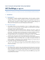
User manual and
product documentation
2013
AEC Buildings
2D TO 3D BUILDING QUANTITY ESTIMATING AND
DRAWING SOLUTION AT LIGHTNING SPEED
Yudhishtirudu Gaddipati
AEC Logic
11/19/2013
Table of Contents
1
2
3
4
Introduction: ......................................................................................................................................... 5
1.1
Present Scenario: .......................................................................................................................... 5
1.2
Aim of this program ...................................................................................................................... 5
1.3
Cost Benefit Ratio ......................................................................................................................... 5
Technical Specifications ........................................................................................................................ 6
2.1
Memory Usage .............................................................................................................................. 6
2.2
Verifying Virtual Memory Allocation ............................................................................................ 6
Managing Input DXF Files ..................................................................................................................... 6
3.1
What is DXF File ............................................................................................................................ 6
3.2
Why DXF ........................................................................................................................................ 7
3.3
Basic layers & objects required ..................................................................................................... 7
3.4
Step by step creation of DXF from AutoCAD ................................................................................ 8
Launching AEC Buildings ..................................................................................................................... 14
4.1
How to start the Program ........................................................................................................... 14
4.2
New Project - Importing 2D DXF file ........................................................................................... 15
4.3
Sample DXF Input files ................................................................................................................ 17
4.4
Scan Radius ................................................................................................................................. 18
4.5
Options ........................................................................................................................................ 19
4.5.1
General ................................................................................................................................ 19
4.5.2
Reports ................................................................................................................................ 20
4.5.3
Reinforcement .................................................................................................................... 20
4.5.4
Colors .................................................................................................................................. 20
4.6
Open Project ............................................................................................................................... 21
4.7
Program Interface ....................................................................................................................... 21
4.8
Customizing Application Settings ................................................................................................ 22
4.8.1
Default Managers................................................................................................................ 22
4.8.2
Storey Level Settings ........................................................................................................... 23
4.9
5
Element Property Definitions...................................................................................................... 24
Modeling the Project Building ............................................................................................................ 26
5.1
Setting number of floors/storeys ................................................................................................ 26
5.2
Element default size settings ...................................................................................................... 26
5.3
5.3.1
Storey Navigator ................................................................................................................. 27
5.3.2
My first project building ...................................................................................................... 28
5.4
Reference lines ............................................................................................................................ 29
5.5
Understanding Plinth composition ............................................................................................. 30
5.5.1
Plinth Beams ....................................................................................................................... 30
5.5.2
Plinth Walls ......................................................................................................................... 30
5.5.3
Plinth PCC ............................................................................................................................ 30
5.5.4
Plinth Fill .............................................................................................................................. 30
5.5.5
Plinth Columns .................................................................................................................... 30
5.6
Excavation Lines .......................................................................................................................... 31
5.7
PCC Leveling Course .................................................................................................................... 32
5.8
Footings ....................................................................................................................................... 32
5.9
Beams .......................................................................................................................................... 33
5.10
Columns ...................................................................................................................................... 35
5.11
Walls ............................................................................................................................................ 36
5.11.1
External Walls ..................................................................................................................... 37
5.11.2
Internal Walls ...................................................................................................................... 37
5.12
Openings ..................................................................................................................................... 38
5.13
Staircases .................................................................................................................................... 38
5.13.1
Geometry ............................................................................................................................ 38
5.13.2
Drawing steps...................................................................................................................... 38
5.13.3
Rule-of-Thumb Formulae .................................................................................................... 39
5.13.4
Staircase boundary.............................................................................................................. 39
5.13.5
Staircase Flights................................................................................................................... 39
5.13.6
Defining ascending order .................................................................................................... 39
5.14
6
Storey data Tab ........................................................................................................................... 27
Slabs ............................................................................................................................................ 40
Reports ................................................................................................................................................ 40
6.1
Volume based reports ................................................................................................................. 41
6.1.1
Volume summary Report .................................................................................................... 41
6.1.2
Detailed Volume reports ..................................................................................................... 42
6.1.3
Sample Volume Report - Columns ...................................................................................... 42
6.2
7
Area Based Reports ..................................................................................................................... 43
6.2.1
Summary Report ................................................................................................................. 43
6.2.2
Detailed Reports ................................................................................................................. 44
6.2.3
Sample Staircase Plastering Area Report ............................................................................ 45
6.2.4
Sample Internal Plastering Area Report.............................................................................. 46
6.2.5
Sample External Plastering Area Report ............................................................................. 47
6.2.6
Sample Ceiling Area Report ................................................................................................ 49
6.2.7
Sample Anti-Termite to Excavation Area Report ................................................................ 50
6.2.8
Shuttering Area Reports...................................................................................................... 51
6.2.9
Sample Shuttering Area - Footing ....................................................................................... 52
6.2.10
Sample Shuttering Area - Beam .......................................................................................... 52
6.2.11
Sample Shuttering Area - Column ....................................................................................... 53
6.2.12
Sample Shuttering Area - Lintel .......................................................................................... 53
6.2.13
Sample Shuttering Area - Staircase ..................................................................................... 54
6.2.14
Sample Shuttering Area - Slabs ........................................................................................... 54
6.2.15
Reinforcement Quantity Report - Items ............................................................................. 55
6.2.16
Reinforcement Quantity Report - Sample .......................................................................... 56
3D Modeling ........................................................................................................................................ 57
7.1
Sample straight 3 floor building- Wireframe .............................................................................. 59
7.2
Sample straight 3 floor building- Shaded .................................................................................... 60
7.3
Sample straight 3 floor building- only slabs ................................................................................ 60
7.4
Sample straight 3 floor building- only Staircase ......................................................................... 61
7.5
Sample 7 Floor building- only Brickwork .................................................................................... 61
7.6
Sample straight 4 floor building- Plan ......................................................................................... 62
7.7
Sample straight 4 floor building- Model wireframe ................................................................... 62
7.8
Sample straight 4 floor building- Model Shaded ........................................................................ 63
7.9
Sample complicated 7 floor building- Plan ................................................................................. 63
7.10
Sample complicated 7 floor building- Model .............................................................................. 64
7.11
Sample complicated 10 floor building- Plan ............................................................................... 64
User manual and product documentation
AEC Buildings program
- A 3D SOLUTION TO ESTIMATE BILL OF QUANTITIES FOR CIVIL ITEMS AND DRAWING FOR BUILDING PROJECTS
1
Introduction:
1.1 Present Scenario:
1. AEC Buildings is a proactive application designed keeping in view the engineers, architects,
managers, builders and other suppliers spending several weeks in designing conceptual plans or
spend hours of their time in understanding the drawing and recreating as they require time and
again like quantity calculations, 3D drawing, progress reporting, coordinate drawings and
element wise sectional plans for construction among several other benefits.
1.2 Aim of this program
2. AEC Buildings performs the same functionality as that of a building quantity surveyor, a
draftsman and an estimating engineer working all together to estimate quantities and produce
Drawing while seamlessly integrating AutoCAD.
3. AEC Buildings captures data from AutoCAD drawings, categorizes, stores them in tables and
works out quantities element wise and level wise for your analysis, planning, scheduling and
procurement. AEC Buildings captures 2D drawing objects with original coordinates, determines
the positioning and member sizes and models with respect to levels defined/defaulted.
4. The program publishes the entire model geometry to ERP programs and Excel. The program also
summarizes the several reports volume and area based apart from shuttering areas.
5. Finally the program models the entire structure back to the CAD 2D and 3D drawings GOOD FOR
CONSTRUCTION. Therefore AEC Buildings 2009 is the simplest and quickest innovative 3D
Quantity Manager to understand any kind of AutoCAD drawing plan and capture data, do
routine design, draw 3D on AutoCAD and do more for you.
6. In short this is the program that is doing a job of a quantity engineer cutting down his time to
mere 5%. In other words using the program can be 100 times faster producing more accurate
results than ever before.
1.3 Cost Benefit Ratio
7. AEC Buildings performs engineers major routine drafting job while freeing them to concentrate
more on other priority assignment like data verification, checks and over all view of the project
design, implementation and monitoring. Using this program can set off your quantity estimation
and drawing COSTS to as high as 90% that is being spent today while TIME saving as high as 90%
of project delays due to this job.
2
Technical Specifications
2.1 Memory Usage
8. AEC Buildings is a light weight XML based data file and drives your AutoCAD Application which is
a 32-bit application and is limited to 4 GB of virtual address space. Typically, on a 32-bit
machine, Microsoft® Windows® reserves 2 GB of the 4 GB virtual address space of any process
for the operating system and leaves the remaining 2 GB for the application process (including
the space for the code pages, the stack, and all dynamically allocated memory). To verify virtual
memory allocation on Windows XP:
2.2
Verifying Virtual Memory Allocation
9. Carryout the following steps.
a. Click Start menu Settings Control Panel.
b. In the Control Panel, double-click System.
c. In the System Properties dialog, click the Advanced tab.
d. In the Performance field, click Settings.
e. In the Performance Options dialog, click the Advanced tab.
f. In the Virtual Memory field, click Change.
10. To verify virtual memory allocation on Windows XP :
a. Click Start menu All Programs Accessories, and run the command prompt.
b. To change the virtual memory allocation back to 2 GB, enter: BCDEDIT
/SetIncreaseUserVa 2048.
c. Note if you are not able to set this value, when you run the command prompt, right-click
and select Run as Administrator.
d. To verify the virtual memory allocation, enter BCDEDIT.
e. In the boot entry option list, the value displays with the IncreaseUserVa option.
f. Your system should have at least 3 GB set aside for the paging file size to fully utilize the
available address space. Every concurrently running application is sharing the available
paging file size, so setting it to something more than 3 GB (such as 4 GB) is
recommended.
3
Managing Input DXF Files
11. User manual and product documentation of AEC Buildings referred here in after as the Program
in the entire documentation as explained.
3.1 What is DXF File
12. The Program requires Data eXchang eable Format (DXF) as input file, generally produced on any
CAD platform as explained in the chapters below to start a new project. The file can be opened
with most applications from simple Notepad, Word, Excel, Browsers including by CAD Programs.
DXF Icon
1. Can be opened with most programs from simple
Notepad, Word, Excel, Browsers
2. Can be opened by ANY CAD Program like AutoCAD,
Micro Station, RHINO
3. Can be opened by any VERSION of CAD program
AutoCAD
icons
1. Can be opened by only AutoCAD
2. Version limitations NOT allow to open
3. Other CAD programs can NOT open
13. DXF file is a representation of each drawing object in text format and arranged with set of rules
in predefined formats. For example a graphical line object is represented by a start and end
points objects while the start point object again is represented by three coordinates in the order
of X, Y & Z with object codes allotted to each object.
3.2 Why DXF
14. The disadvantage of using AutoCAD is that version compatibility becoming a big problem to
access and work under collaborative environment. For example a drawing created using
AutoCAD version 2010 at Head office cannot be opened at site office using AutoCAD 2006.
15. Inter application data transfer (estimating application to direct AutoCAD) is not a proven
technology to perform faster output. A simple commercial building contains tens of thousands
of objects and takes more time to generate a 3D model direct to the AutoCAD or any other CAD
based application due to COM compatibility. Whereas similar size of file using DXF can be
written in few seconds. Therefore we can assess that using DXF files for reading input and
creating output is faster by more than 100 times than using AutoCAD with several version
limitations.
3.3 Basic layers & objects required
16. AEC Buildings requires 2D project plan in DXF format with all objects as CLOSED POLYLINES
mostly in the form of RECTANGLES. Staircase needs direction lines as exceptional case.
17. Create NINE critical new Layers as given under.
a. Boundary
b. Footings
c. Columns
d. Beams
e. Walls Internal
f. Walls External
g. Wall Openings
h. Slabs
i. Staircases
18. To do fast and accurate drafting use 'Rectangle' command and draw rectangles for each one of
element on respective layers. AEC Buildings removes all drawing objects except the following:
a. Lines (required only for staircase directions)
b. Arcs (can be used for beams, walls, and slabs)
c. Polylines (all objects)
d. Circles(columns)
19. Save it as DXF and You have done it!!!
20. For more help on these, see topic Step by step creation of DXF from AutoCAD
3.4 Step by step creation of DXF from AutoCAD
21. User is advised to save a back up copy of original drawing file to a separate location. Sample
plan drawing opened in AutoCAD is as under.
22. Create NINE new Layers as explained in the above topic: Few examples are shown below.
23. If your drawing already contains existing closed polylines for these types of objects, your work is
already half done. Else, take 'Rectangle' (shortcut 'rec)' command and draw rectangles for each
one of them. Make sure that when you are drawing columns your current layer be set on.
24. If you have these objects drawn on a different layer, simply push them to the new layers.
Alternatively you can also indicate layer names on the program form. Make sure that no
unwanted closed poly lines are present on the respective layers. If the is not ensured, the
program would pick up all those objects as if they are the real objects to be handled.
25. It may be wise to keep cyan for columns, blue for beams, silver for slabs and staircases and
white for walls for easy identification and visual effects to remember.
26. Keep line weight as 1mm and set it ON status to identify your work than the existing Architect
work. Set default line weight and line color before starting drawing.
27. Take symmetrical effects to mirror your work in X & Y directions.
28. Draw Slab closed polylines and push them to Slab layer to select them when program prompts.
29. Avoid overlapping and crossovers/fouling of beams, columns and walls to expect better results.
Make sure that beams start with a columns/beam ends and end with the beam or column.
Follow all clear dimensions only.
30. Pick up a beam with diagonally opposite corners for each object. Draw in the order of primary
beams connecting columns, the secondary beams column-beam or beam to beam connecting
primary beams followed by tertiary beams and so on.
a. >> Finish all beams connecting column to column.
b. >> Then take up secondary beams connecting column and beams if any
c. >> Next take up beams running between main beams
d. >> Next take up tertiary beams running between secondary beams and so on until you
reach the last level.
e. >> This process gives better and visually/technically stable structure.
31. Then draw the wall lines.
32. Push all the columns to 'Columns' layer, beams to 'Beam' layer and walls to 'wall layer'.
33. Make sure that beams have minimum 230 / 250 mm width while walls can have lower width
34. Use quick filters, 'fi' command AutoCAD prompt or right click on the AutoCAD screen to 'Quick
Select'. Select require layer.
35. Remember to work on original coordinates to keep global integrity of your project.
4
Launching AEC Buildings
4.1 How to start the Program
36. Double click on the shortcut 'AEC Buildings from your system Desktop or Program Files >> AEC
Logic >> AEC Buildings. This would launch the application as shown under.
4.2 New Project - Importing 2D DXF file
37. Program Flash opens for Creating a New Project, Opening a Project, Opening Samples Projects
a. Numerous samples Project files are made available for the user to practice.
b. Numerous sample DXF input files are made available for the user to practice
c. New project requires DXF input file as explained in the steps below
d. Click New (From DXF) to create new project though 5 steps as explained in the next
paragraph
38. Sequence of 5 steps is shown as follows. Select respective Boundary, Column, Beam, Wall, Slab,
Staircase and so on layers by mapping the DXF layers.
a. Choose either Browse or DXF Samples.
b. Select the DXF input file from the source location or choose the sample file. To find the
sample DXF input files read the topic Sample Input DXF Files
c. Set Layers with the component available from the DXF input file
d. Set drawing scale
e. Set the scan radius. This takes care of human errors, since gaps between the
column/beam /wall connections are adjusted by the program. Next topic explains more
about how to estimate scan radius.
f. Import to finish
4.3 Sample DXF Input files
39. The Program provides sample DXF input files for the user to practice and understand the
program. The samples are well designed to explain the user with several program features. It is
recommended that the user may practice using input files from Sample 1 available when clicked
on Samples link on Import DXF form.
4.4 Scan Radius
40. The Scan Radius is useful to perform the following functions to drive the program to perfection.
a. To combine reference lines falling within the scan radius range. For example we may be
having two reference lines separated with a distance of less than the scan radius. Coding
these two lines as separate may be duplication of numbering
b. If the wall and beam centre lines are separated at a distance less than the scan radius
the wall load is assumed to be transferred to the beam lying within. More over the wall
and beam shall assume same centre line for all references
c. Some buildings may be having wider beams/walls necessitating setting of higher scan
radius value. User may accordingly set this value to suit the project behaviors with
several trials.
d. Higher scan radius may skip the required reference line leaving some beam geometry.
Therefore setting this value is important to import perfect geometry as desired.
4.5 Options
41. The Program drives with the assumptions based on the application wide variables set by the
user in several tabs of the Options form. Functional uses of each variable are explained below.
4.5.1 General
42. Decimals: this decides how many decimal places are required in writing data to the grid and
reports.
43. Text Size: Sets for generating the annotation size on the drawings according to readability and
user requirement.
44. Riser Height: Staircase default riser height to appear in project defaults.
45. Tread Width: Staircase default tread to appear in project defaults.
46. Opening Height: Default Opening height to appear in project defaults
47. Opening Z offset: Default Opening Z offset measured from floor level to appear in project
defaults.
48. Versine: Maximum bulge value from a straight chord of an arc segment for arc walls and beams
to controls smoothness of arcs.
4.5.2 Reports
49. Excavation stages: Earth work excavation is categorized depending on stages of depth to cater
for more efforts and costs. Program divides depths of excavation in to these stages and reprots
are prepared.
50. Plinth composition sand: To achieve plinth height or to build the gap between the plinth plain
cement concrete course (PCC) layer and surrounding ground level (GL) we normally fill partly
with earth and partly with sand. Default value for sand is set here.
51. Plinth composition Earth: Default value for earth is set here.
52. DPC (Damp Proof Course): All walls are in general protected from ground dampness by providing
rich concrete layer called DPC and its default thickens is set here.
53. Lowest Floor PCC thickness. The floor immediately over the ground shall have PCC layer than
regular slab. Default value for PCC is set here.
54. Plinth Protection: Certain strip around a building plinth is protected from rain water penetration
to foundation. Default value of this width is set here.
55. Rain Water Pipes: Roofs are provided with rain water pipes at an interval of this default value to
safely drain off water.
56. Site Clarence Depth: Every site needs to be scraped depending on the quantum accumulation of
debris. The average depth of debris is required to estimate quantity for disposals and
management. Default value of this depth is set here.
4.5.3 Reinforcement
57. Since the program does not design the rebars, but a quick estimation of approximate quantity
of rebar can be estimated based on dosage per volume of each RC element as a rule of thumb.
Such values are set to guide the program by default. Users may with their experience choose
the values to generate reports
4.5.4 Colors
58. Default colors could be set for different elements for the program to send output according to
these settings.
4.6 Open Project
59. On the Start Up dialog click Open Project to finish in any unwished editing required, or look at
the Recent Files list that you opened most recently. To open a AEC Buildings 2009 file, use any
of the following methods.
60. In the Open dialog, navigate to the folder where the project file resides. If necessary, for Files of
type, select the appropriate file type to see those files in the folder. To open files in AEC
Buildings from Windows Explorer double-click a project
4.7 Program Interface
61. The AEC Buildings interface is designed to simplify 2D to 3D workflow. User can navigate to
different defaults suiting to work stage. Read the following topics to familiarize with the basic
parts of the AEC Buildings interface.
62. The main program Interface contains the following components. The actions performed here is
to capture layer wise elements to push data to respective grids, setting reference numbering,
determine the member properties and levels to finally calculate physical quantities, report
coordinates and create drawings.
63. Main Application window contains Floors/Storeys list, Project Default Manager, Data grids,
Members, Graphics area. Project Default Manager to drive different initial values mostly related
to elevation of the model before generating data for several elements. Whereas the graphic grid
enables the user to show the objects in plan and model.
64. See the next topic Model the Project Building to know more about model generation
65. Click the Story Data tab to see element wise data with corresponding graphics
4.8 Customizing Application Settings
66. AEC Buildings captures drawing data from DXF and writes data files using default values set in
the Application Default Manager for different building elements. For example column height is
set to 3 meters taking input from the Application level settings. These settings are application
wide and when changed and saved would reappear for the next future projects.
4.8.1 Default Managers
67. Program provides three levels of managing data to automate work fastest way. Application
default manager stores repeated defaults at application level to provide the latest defaults to
every new project taken up. Whereas Project Default Manager while inheriting application
defaults sets data across the project before actual values are input. Most building construction
members do have common dimensions that could be set to flow from defaults. Whereas the
third level is the Level Manager to push the entre model fror one level to the other instead of
changing every floor.
4.8.2 Storey Level Settings
68. Level Manager is used to change the levels of the entire structure at one go. Change of any
column at any floor level would drive the entire structure remodeled. All connected levels of
elements get changed maintaining the integration. Other values like floor height, L/D ratio, least
count and slab thickness required to generate model are assumed for the entire structure
uniformly. User is not barred from changing the individual member sizes in the generated data
grids as per the real model.
69. Storey Level Manager provides changes to be made across the whole floor/Storey uniformly.
The whole storey is affected by such changes.
70. If Columns To level is changed to a higher value all the storeys above the current floor shall
raised by such variation.
71. If Columns From level is changed to a higher value all the storeys below the current floor shall
lifted by such variation. This will affect all elements below the current floor. AEC Buildings 2009
recommends not changing From levels as this will affect many changes for other elements.
4.9 Element Property Definitions
72. Column Height: Is defined as the height from the top of the slab below to the bottom of the slab
above. For the bottom most columns the height is from the top of the plinth to the bottom of
the floor above.
73. Beam Breadth: Is defined as the breadth or width of beam or transverse dimension along X or Y
directions of the drawing top plan (XY Plane).
74. Wall Thickness: Is defined as the thickness or width of wall or transverse dimension along X or Y
directions of the drawing top plan (XY Plane).
75. Slab Thickness: Is defined as the thickness or height of slab in Z direction. This dimension shall
be converted by AEC Buildings 2009 to levels depending on the location.
76. Openings- Offset From Wall Left (X/Y): The offset distance from left corner of the wall if viewed
from front face or right face of the wall. This is a transverse dimension along X or Y directions of
the drawing top plan (XY Plane).
77. Opening Width: This is a transverse dimension of opening along X or Y directions of the drawing
top plan (XY Plane).
78. Opening Height: defined as the height in Z direction on drawing top plan (XY Plane).
79. Lintel Thickness: Is equal to the Wall Thickness and defined as the thickness or width of lintel or
transverse dimension along X or Y directions of the drawing top plan (XY Plane).
80. Lintel Left Offset: Is defined as the bearing on to the left of the wall from the edge of the
opening along X or Y directions of the drawing top plan (XY Plane).
81. Lintel Right Offset: Is defined as the bearing on to the right of the wall from the edge of the
opening along X or Y directions of the drawing top plan (XY Plane).
82. Lintel Depth: Is the depth of the lintel along height of the building or in the Z direction on the XY
plane.
83. Sunshade Projection: Sunshade projection on the outer wall or loft on the inner walls where
ever required.
84. Sunshade Start Thickness: Is the thickness at the wall face.
85. Sunshade End Thickness: Is the away from the wall face.
86. Roof Height: Height of the ridge above boundary/border line. This is applicable only for sloped
roofs.
87. Foundation Depth: Depth of the foundation below ground level for the buildings having storeys
above ground level. For the buildings having storeys below ground level the depth is the below
the bottom most storey.
88. Plinth Height: Is applicable to the buildings having storeys above ground level only. For the
buildings having storeys below ground level AEC Buildings 2009 shall not provide any plinth.
89. PCC Thickness: Thickness of the leveling course to be laid between the structural footings and
the excavation in the Z direction on the plan (XY Plane).
90. Footing Thickness: Is thickness of structural footings in Z direction on the plan (XY Plane).
91. Staircase Max Rise: Maximum rise that is set for the AEC Buildings 2009 to design within the
space and length supplied to, while capturing data from AutoCAD drawing plan. AEC Buildings
2009 shall adjust the Rise depending on the number of flights, their lengths and the floor heights
set in the Application Default manager.
92. Staircase Min Tread: Minimum Tread that is set for the AEC Buildings 2009 to design within the
space and length supplied to, while capturing data from AutoCAD drawing plan. AEC Buildings
2009 shall adjust the Tread depending on the length of the flights and the floor heights set in the
Application Default manager.
93. Flight W: Flight width for the steps to span across for the stair path.
94. Landing W: Landing width for the steps to connect between two flights. This is in other words
can be treated as the extent beyond end of flight reach
95. Waist Slab Width: Is the width of the slab/beam below steps for structural support. This may
vary to a stringer beam width.
96. Waist Slab Thickness: Is the thickness of the slab/beam below steps for structural support. This
may vary to a stringer beam thickness.
5
Modeling the Project Building
97. As the DXF input file containing critical layers and are imported in to the AEC Buildings, the
Program pops up the window as under to set project model with default property variables.
These project wide settings default to all respective elements groups. Individual change of
properties could be done from the element data grid.
5.1 Setting number of floors/storeys
98. Select number of floors that the proposed structure is to be built and click Apply to generate
data. The image above shows data for G+4 floors.
5.2 Element default size settings
99. All member sizes in plan are generally picked up from the DXF drawing. For example the column
breadth and depth are picked up from rectangle dimensions and for circular sections the
diameter is picked up while the height of columns are calculated by the program based on levels
being fixed under level manager.
For beam and walls the drawing lengths and widths are
picked up from the drawing.
Depths of beams are fixed calculated by the program
from a formula Beam L/D Ratio and Least Count to
maintain accepted practice, feasibility, and formwork
availability. Individual beam depths could be modified
from Storey Data >> Beams >> Select the beam and edit
levels FROM and TO.
100.
For slabs the dimensions are same as that are in the drawing plan. Thickness is
calculated by the program as per the levels specified under level manager.
5.3 Storey data Tab
101.
Each building element contains storey wise data tabulated in Data Tables. These data
may be changed as required in your project. Reference fields are not editable since they indicate
object references to the model drawing. Each building element object is listed in the Data Tables
with dimensions and position.
102.
AEC Buildings does not provide editing certain data like in the field “Area” of columns,
footings and slabs captured from the Drawing plan. Only the sectional dimensions like levels
and widths/breadths are editable since they are geometric and taken from defaults.
5.3.1 Storey Navigator
103.
The tree view lists are the project storeys in ascending order from bottom. The selected
storey is the active storey for AEC Buildings to open data related to that floor.
5.3.2
My first project building
104.
BY default the program keeps all layers opened in both plan and model graphs as shown
on the images above and below. Unser need to set these layers in off mode to see individual
layer wise data in graph.
5.4 Reference lines
105.
Reference lines are automatically drawn by the AEC Buildings by setting two
construction lines for each column and are rotated in two principally orthogonal directions to
the alternate edges of the column. In certain cases single reference lines are assumed by the
program
106.
These construction lines shall be truncated to form reference lines in red color on a
boundary fence created by the AEC Buildings. All the major building elements are identified by
this reference line numbering as per annotation style explained in the next topic
5.5 Understanding Plinth composition
5.5.1 Plinth Beams
107.
AEC Buildings adds beams to the Plinth which are generally called plinth beams. These
are placed at either at the plinth top level or at the ground level depending on your project
requirements.
108.
In some instances the outer beam is laid at the ground level and in such instances we
term the beam as grade beam or ground beam. AEC Buildings considers both types of beams as
plinth beams.
5.5.2 Plinth Walls
109.
Plinth fills are protected up to certain height by outer plinth beams and balance if fall
short shall be protected by walls. These walls if built below plinth beams take support on the
wall footing below ground level. You may have to add a footing to the plinth wall as if you were
adding to columns in the footings layer before the Drawing Setup Wizard closes.
110.
Only outer plinth walls are necessary to be built unless your project specifically requires
so. In case if plinth beams are built at ground level for some reason, plinth walls shall be
constructed above the plinth beams. However the quantity variations shall not be affected with
this option.
5.5.3 Plinth PCC
111.
Plinth top is laid with Plain Cement concrete layer to support flooring of the G (+0)
storey. This PCC is assumed to be matching at the plinth level and its depth extends towards
ground level. Generally thickness of this layer is 75 mm to 150 mm depending on the loads
expected and soil conditions beneath.
5.5.4 Plinth Fill
112.
To achieve plinth height or to build the gap between the plinth Plain Cement Concrete
course layer and surrounding ground level we normally fill with earth. This is generally called
plinth fill.
113.
AEC Buildings calculates quantities based on the areas of defined extent of the Plinth
and the levels that have been set for these elements. Necessary deductions shall be calculated
by AEC Buildings to affect plinth beams, walls etc.
5.5.5 Plinth Columns
114.
Likewise for other storeys the plinth is built up by columns to the extent from
surrounding ground level to the plinth top level.
115.
Plinth columns shall extend to the foundation last footing/pedestal from irrespective of
whether the section is foundation or plinth
5.6 Excavation Lines
116.
The bottom most elements are assumed as excavation lines offsetting a predefined
value from the last footing. These lines are required for carrying out excavation activity for your
building project.
117.
Area excavation shall be treated as separate from this foundation trench excavation
lines. If your project has only storeys above ground then the excavation depth shall be taken
from the below the plinth bottom level or from the ground level. Alternatively if the project has
storeys below ground level then depth of the foundation shall be taken from bottom level of the
last storey. Excavation for the storeys shall have to be separately considered as per the existing
ground levels and the extent by which your project requires.
5.7 PCC Leveling Course
118.
The Plain Cement Concrete elements are assumed to be same as excavation lines in plan
offsetting a predefined value from the last footing.
119.
Thickness of the PCC Leveling course shall be by default set from the Project Default
Manager “Foundation PCC Th.” field.
5.8 Footings
120.
For AEC Buildings 2009 any kind of footing is just as simple as you get from on an
AutoCAD drawing in DXF format. You can create combined footings, single/multiple rafts or
isolated footings or combination of these for single footing.
121.
Footings are generated by AEC Buildings. Sizes of the footings are set by AEC Buildings
by drawing dimensions. Shape of the footing shall be the same as that as drawn.
5.9 Beams
122.
Program creates beams between column edges where ever reference lines exist through
columns. Program reference lines already set during column generation are applied to the
beams as well to set same reference when the beam centerline falls within the scan radius to
treat all of them belonging to one reference line. If the beam centerlines are spaced farther than
the scan radius the program sets additional reference line.
123.
Secondary beams connecting main beams may be required at many places. You may
draw them from the face of the main beam. See topic Step by step creation of DXF
124.
AEC Buildings requires you to draw all the additional beams before DXF, if some beam is
omitted, redraw and import the drawing. During DXF creation one could add arc beams to the
project. Use cursor snaps to other structural elements, such as the main beams or column faces
when you sketch a curved beam. Corners are not chamfered if the arc start tangent is not
perpendicular to the face of the support. The error is so insignificant in your estimate and so
that can be neglected.
Column and beam junctions shall be formed by the program
automatically as shown in the diagrams below. Slab shall be treated
as covering on the entire top surface of columns and beams to
maintain rhythm of levels as defined in level manager.
Corners are not chamfered if the arc start tangent is not
perpendicular to the face of the support. The error is so insignificant
in your estimates and so that can be neglected
5.10 Columns
125.
Program sets up column grids through all Project Columns in two orthogonal/opposite
directions. These two directions need not be perpendicular. AEC Buildings assumes that two
alternate edges of columns carry beams. Program automatically sets reference lines through
centroid of all the Project Columns perpendicular to each Project Columns edge and removes
duplicate if these columns fall within the scan radius to treat all of them belonging to one
reference line. If the columns are spaced far than the scan radius the program sets additional
reference line.
126.
AEC Buildings instantly draws grid in green color along the architectural column grid on
“where is basis” and presents you to verify the grid and edit to suit your requirement. You may
require inserting more columns or resizing, reshaping, relocating and reorienting them as the
case may be.
5.11 Walls
127.
Drawing Setup Wizard prompts you to draw an outer wall boundary along columns
outer edges.
128.
AEC Buildings automatically determines the front, back, left and right faces of the
building so as to align sunshades and identify external faces of the building apart from
recognizing the walls as externals. However in exceptional case due to drawing ambiguity same
may not align in the desired direction. The user may change the alignment of these objects in
the options given for each wall opening in opening storey data.
129.
By default all openings are assumed to be windows for external walls and doors for
internal walls. User may correct the opening data.
5.11.1 External Walls
5.11.2 Internal Walls
5.12 Openings
5.13 Staircases
5.13.1 Geometry
130.
You can define your staircase by sketching boundaries and risers on plan during or
before Drawing Setup Wizard session. AEC Buildings expects that your staircase plan is already
drawn on the drawing as shown in the Sketch 1.
5.13.2 Drawing steps
131.
Draw Staircase boundary defining a boundary line enclosing all your flights/runs as
shown in sketch 2.
132.
In DXF input drawing create centre line for each flight/run starting from start of stairs to
the end of stairs. The direction of the line should be along the ascending of stairs as shown in
sketch2. Use midpoint snaps while drafting lines on the AutoCAD to get accurate results.
5.13.3 Rule-of-Thumb Formulae
133.
The following is a rule-of-thumb formula for interior stairs, as specified in the
Architectural Graphic Standards.
a. Riser + Tread = 17.5 inches: 7.5 inches for the riser height; 10 inches for the tread depth.
b. Riser * Tread = 75 inches.
c. 2(Riser) + Tread is greater than or equal to 24 inches (minimum threshold) or less than
or equal to 25 inches (maximum threshold).
d. Riser x Tread = 400 to 500 (In metric units centimeters)
5.13.4 Staircase boundary
134.
Closed polylines created in Staircase layer are assumed to be staircase pits/boundaries
where projects need a stair case to be fit into.
5.13.5 Staircase Flights
135.
Program requires drawing staircase flights in line format. Simple lines may be drawn for
each flight that composes to form a complete staircase from one floor to the other in a stair
case pit. The lines could be either of the following, a straight single line, two lines in opposite
directions forming as folded doglegged flights , three lines forming U shaped flights, four lines
forming closed shape flights.
5.13.6 Defining ascending order
136.
Drawing order shall be in the ascending order, i.e., start point of the line shall be at the
start of the lower most step and the end point shall be end of the higher most step.
5.14 Slabs
137.
Slab with any number of openings could be extruded by the pprgram. AEC Buildings
recognizes closed polylines either as slabs or openings as the case may be.
6 Reports
138.
In line with the aim of this program to arrive at most accurate quantities of several
cumbersome quantifications at lightning speed, the program gives the following types of reports
for smooth running of construction business saving huge time and costs in calculating these
quantities.
139.
Volume based reports
140.
141.
142.
Area Based reports
Formwork calculations
Element wise coordinates report to manage construction
6.1 Volume based reports
143.
These are again reported as summary and detailed for the following items which are
generally measured in volumes for cost estimation, analysis and contractual
144.
Items covered in volume reports are as under
Foundation
Plinth
Plinth Composition
G (+0)
G (+1)
G (+2)
6.1.1
Volume summary Report
Volumetric Items - Units All In Cubic Meters dings 2009 Generated Quantity Report
Storey
Element/ Reference
Volume
Foundation
Excavation in Foundation 0 to 2
-51.2
Foundation
Foundation Backfilling
-62.144
Foundation
Damp Proof Course
0.064
Foundation
Leveling Course
2.56
Foundation
Footing Concrete
5.88
Plinth
Columns
6.963
Plinth
Beams
17.813
Plinth
Outer Walls
9.202
Plinth Composition
Earth Filling
-24.618
Plinth Composition
Sand Filling
-6.154
Plinth Composition
PCC Filling
-6.154
Plinth Composition
Damp Proof Course
-0.154
G (+0)
Columns
9.495
G (+0)
Beams
17.813
G (+0)
Inner Walls
27.841
G (+0)
InnerWall Opening
3.183
G (+0)
Outer Walls
69.381
G (+0)
OuterWall Opening
7.958
G (+0)
StairCase
0.61
G (+0)
Slab
40.096
6.1.2 Detailed Volume reports
145.
The items being covered in the detailed estimate are the same as that shown in the
summary. The detailed report contains length, width and depth with reference, position and
direction attached to every calculation.
6.1.3
Sample Volume Report - Columns
6.2 Area Based Reports
6.2.1
Summary Report
2009 Generated Area Report
Area Based Items - Units All In Square Meters
Storey
Element/Reference
Foundation
Excavation in Foundation 0 to 2
Quantity
25.6
Anti-Termite to Excavation
Area
25.6
Foundation Backfilling
Quantity
73.965
Damp Proof Course
Quantity
25.6
Leveling Course
Quantity
25.6
Footing Concrete
Quantity
19.6
Footing Shuttering
Footing
33.6
Columns
Quantity
3.165
Column Shuttering Area
Column
101.2
Beams
Quantity
58.38
Beam Shuttering Area
Beam
211.335
External Plastering
Outer Walls
72.37
Outer Walls
Quantity
29.255
Earth Filling
Quantity
61.545
Sand Filling
Quantity
61.545
PCC Filling
Quantity
61.545
Damp Proof Course
Quantity
61.545
Columns
Quantity
3.165
Floor Area
Column
223.165
Ceiling Area
Column
223.165
Slab Shuttering Area
Column
225.06
Plinth
Plinth Composition
G (+0)
Area
Column Shuttering Area
Column
138
Internal Plastering
Column
671.707
Beams
Quantity
58.38
Beam Shuttering Area
Beam
211.335
Inner Walls
Quantity
22.583
InnerWall Opening
Quantity
3.183
Lintel Shuttering Area
Lintel
40.333
Roof Area
Outer Walls
238.055
External Plastering
Outer Walls
420.19
Outer Walls
Quantity
47.586
OuterWall Opening
Quantity
7.958
StairCase
Quantity
4.327
Waist Slab Shuttering Area
Waist Slab
5.082
StairCase Plastering Area
Waist Slab
5.607
StairCase Tread Area
Steps
0
StairCase Raiser Area
Steps
0
Slab
Quantity
267.31
6.2.2 Detailed Reports
146.
The items being covered in the detailed estimate are the same as that shown in the
summary. The detailed report contains length, width and depth with reference, position and
direction attached to every calculation.
6.2.3
Sample Staircase Plastering Area Report
Storey
Element/Reference
G (+0)
StairCase Plastering Area
Shape
L/Dia/Nr
B/Area/Nr
D/H/Nr
Area
Description
Flight1 of Slab1-StairCase1
Rectangle
3.388
1.2
1
4.066
Bottom
Flight1 of Slab1-StairCase1
Rectangle
3.388
1
0.15
0.508
Side 1
Flight1 of Slab1-StairCase1
Rectangle
3.388
1
0.15
0.508
Side 2
Flight1 of Slab1-StairCase1
Triangle
1
0.333
0.175
0.029
Flight1 of Slab1-StairCase1 Step1 Side1
Flight1 of Slab1-StairCase1
Triangle
1
0.333
0.175
0.029
Flight1 of Slab1-StairCase1 Step1 Side2
Flight1 of Slab1-StairCase1
Triangle
1
0.333
0.175
0.029
Flight1 of Slab1-StairCase1 Step2 Side1
Flight1 of Slab1-StairCase1
Triangle
1
0.333
0.175
0.029
Flight1 of Slab1-StairCase1 Step2 Side2
Flight1 of Slab1-StairCase1
Triangle
1
0.333
0.175
0.029
Flight1 of Slab1-StairCase1 Step3 Side1
Flight1 of Slab1-StairCase1
Triangle
1
0.333
0.175
0.029
Flight1 of Slab1-StairCase1 Step3 Side2
Waist Slab
Steps
6.2.4
Flight1 of Slab1-StairCase1
Triangle
1
0.333
0.175
0.029
Flight1 of Slab1-StairCase1 Step4 Side1
Flight1 of Slab1-StairCase1
Triangle
1
0.333
0.175
0.029
Flight1 of Slab1-StairCase1 Step4 Side2
Flight1 of Slab1-StairCase1
Triangle
1
0.333
0.175
0.029
Flight1 of Slab1-StairCase1 Step5 Side1
Flight1 of Slab1-StairCase1
Triangle
1
0.333
0.175
0.029
Flight1 of Slab1-StairCase1 Step5 Side2
Flight1 of Slab1-StairCase1
Triangle
1
0.333
0.175
0.029
Flight1 of Slab1-StairCase1 Step6 Side1
Flight1 of Slab1-StairCase1
Triangle
1
0.333
0.175
0.029
Flight1 of Slab1-StairCase1 Step6 Side2
Flight1 of Slab1-StairCase1
Triangle
1
0.333
0.175
0.029
Flight1 of Slab1-StairCase1 Step7 Side1
Flight1 of Slab1-StairCase1
Triangle
1
0.333
0.175
0.029
Flight1 of Slab1-StairCase1 Step7 Side2
Flight1 of Slab1-StairCase1
Triangle
1
0.333
0.175
0.029
Flight1 of Slab1-StairCase1 Step8 Side1
Flight1 of Slab1-StairCase1
Triangle
1
0.333
0.175
0.029
Flight1 of Slab1-StairCase1 Step8 Side2
Flight1 of Slab1-StairCase1
Triangle
1
0.333
0.175
0.029
Flight1 of Slab1-StairCase1 Step9 Side1
Flight1 of Slab1-StairCase1
Triangle
1
0.333
0.175
0.029
Flight1 of Slab1-StairCase1 Step9 Side2
StairCase Plastering Area
5.607
Total G (+0)
5.607
Sample Internal Plastering Area Report
Storey
Element/Reference
Shape
L/Dia/Nr
B/Area/Nr
D/H/Nr
Area
Description
G (+0)
Internal Plastering
C08-R07
Rectangle
0.3
1
3
0.9
Ext.Col Front
C08-R07
Rectangle
0.3
1
3
0.9
Ext.Col Back
C08-R07
Rectangle
1
0.23
3
0.69
Ext.Col Left
C08-R07
Rectangle
1
0.23
3
0.69
Ext.Col Right
C10-R07
Rectangle
0.3
1
3
0.9
Ext.Col Front
C10-R07
Rectangle
0.3
1
3
0.9
Ext.Col Back
C10-R07
Rectangle
1
0.23
3
0.69
Ext.Col Left
C10-R07
Rectangle
1
0.23
3
0.69
Ext.Col Right
C01-R07
Rectangle
0.35
1
3
1.05
Ext.Col Front
Column
Inner Walls
R11-C12-R13
Rectangle
1
0.112
2.8
-0.314
Left
R11-C12-R13
Rectangle
1
0.112
2.8
-0.314
Right
R11-C12-R13
Rectangle
1.8
1
2.8
5.04
Front
R11-C12-R13
Rectangle
1.8
1
2.8
5.04
Back
R11-C12-R13
Rectangle
1.8
0.112
1
-0.202
Top
C13-R05-C11
Rectangle
1
0.11
2.85
-0.314
Left
C13-R05-C11
Rectangle
1
0.11
2.85
-0.314
Right
C13-R05-C11
Rectangle
1.61
1
2.85
4.589
Front
R11-C12-R13
Rectangle
0.75
1
1
-0.75
Front openg
R11-C12-R13
Rectangle
0.75
1
1
-0.75
Ext.wall Back openg
R11-C12-R13
Rectangle
1
0.112
1
0.112
Left Jamb openg
R11-C12-R13
Rectangle
1
0.112
1
0.112
Right Jamb openg
R11-C12-R13
Rectangle
0.75
0.112
1
0.084
Top Sill
R11-C12-R13
Rectangle
0.75
0.112
1
0.084
Down Sill
Open
6.2.5
Sample External Plastering Area Report
Storey
Element/Reference
Shape
L/Dia/Nr
B/Area/Nr
D/H/Nr
Area
Description
C04-R06-C07
Rectangle
3.03
1
0.3
0.909
Outer
R07-C01-R08
Rectangle
2.69
1
0.35
0.941
Outer
C07-R07-C04
Rectangle
3.03
1
0.3
0.909
Outer
C07-R07-C08
Rectangle
1.8
1
0.4
0.72
Outer
C09-R07-C11
Rectangle
1.8
1
0.4
0.72
Outer
R03-C01-R01
Rectangle
2.69
1
0.35
0.941
Outer
R08-C17-R11
Rectangle
2.621
1
0.35
0.917
Outer
R06-C01-R03
Rectangle
4.3
1
0.2
0.86
Outer
Plinth
Outer Walls
Ext.Beam
C04-R06-C07
Rectangle
3.03
1
0.3
0.909
Outer
R07-C01-R08
Rectangle
2.69
1
0.25
0.672
Outer
C07-R07-C04
Rectangle
3.03
1
0.3
0.909
Outer
C07-R07-C08
Rectangle
1.8
1
0.2
0.36
Outer
C09-R07-C11
Rectangle
1.8
1
0.2
0.36
Outer
R03-C01-R01
Rectangle
2.69
1
0.25
0.672
Outer
R06-C01-R03
Rectangle
4.3
1
0.4
1.72
Outer
C04-R06-C07
Rectangle
0.9
1
1
-0.9
Ext.wall opening
R07-C01-R08
Rectangle
1.2
1
1
-1.2
Ext.wall opening
C07-R07-C08
Rectangle
1.2
1
1
-1.2
Ext.wall opening
C09-R07-C11
Rectangle
1.2
1
1
-1.2
Ext.wall opening
R08-C17-R11
Rectangle
0.6
1
1
-0.6
Ext.wall opening
R08-C17-R11
Rectangle
0.6
1
1
-0.6
Ext.wall opening
C04-R06-C07
Trapezoid
0.6
0.1
0.075
0.052
Side1
0.6x(0.1+0.075)/2
C04-R06-C07
Trapezoid
0.6
0.1
0.075
0.052
Side2
0.6x(0.1+0.075)/2
C04-R06-C07
Rectangle
1.2
0.6
1
0.72
Bottom
C04-R06-C07
Rectangle
1.2
0.601
1
0.721
Top
C04-R06-C07
Rectangle
1.2
0.075
1
0.09
Front
C04-R06-C07
Rectangle
1.2
0.1
1
-0.12
Back
R07-C01-R08
Trapezoid
0.6
0.1
0.075
0.052
Side1
0.6x(0.1+0.075)/2
R07-C01-R08
Trapezoid
0.6
0.1
0.075
0.052
Side2
0.6x(0.1+0.075)/2
Open
Sunshade
6.2.6
Sample Ceiling Area Report
Storey
Element/Reference
Shape
L/Dia/Nr
B/Area/Nr
D/H/Nr
Area
Description
C08-R07
Rectangle
0.3
0.23
1
-0.069
Top
C10-R07
Rectangle
0.3
0.23
1
-0.069
Top
C01-R07
Rectangle
0.35
0.23
1
-0.08
Top
C17-R06
Rectangle
0.35
0.23
1
-0.08
Top
C10-R09
Rectangle
0.3
0.23
1
-0.069
Top
C08-R09
Rectangle
0.3
0.23
1
-0.069
Top
R11-C12-R13
Rectangle
1.8
0.112
1
-0.202
Top
C02-R12-C04
Rectangle
1.74
0.11
1
-0.191
Top
C04-R04-C07
Rectangle
3.27
0.11
1
-0.36
Top
C04-R06-C07
Rectangle
3.03
0.23
1
-0.697
Top
C10-R06-C11
Rectangle
2.03
0.285
1
-0.579
Top
C11-R06-C14
Rectangle
3.05
0.23
1
-0.702
Top
Polygon
1
267.31
1
267.31
Bottom
G (+0)
Column
Inner Walls
Outer Walls
Slab
G (+0)
Ceiling Area
Storey
Element/Reference
G (+0)
Floor Area
223.165
Shape
L/Dia/Nr
B/Area/Nr
D/H/Nr
Area
Description
C08-R07
Rectangle
0.3
0.23
1
-0.069
Bottom
C10-R07
Rectangle
0.3
0.23
1
-0.069
Bottom
C01-R07
Rectangle
0.35
0.23
1
-0.08
Bottom
C04-R08
Rectangle
0.35
0.23
1
-0.08
Bottom
Column
Rectangle
0.3
0.23
1
-0.069
Bottom
R11-C12-R13
Rectangle
1.8
0.112
1
-0.202
Bottom
C11-R03-C14
Rectangle
3.05
0.11
1
-0.335
Bottom
R11-C02-R13
Rectangle
1.8
0.112
1
-0.202
Bottom
R05-C13-R06
Rectangle
1.2
0.11
1
-0.132
Bottom
C04-R06-C07
Rectangle
3.03
0.23
1
-0.697
Bottom
R07-C01-R08
Rectangle
2.69
0.23
1
-0.619
Bottom
R08-C07-R11
Rectangle
2.62
0.23
1
-0.603
Bottom
C04-R01-C07
Rectangle
3.03
0.23
1
-0.697
Bottom
R01-C07-R03
Rectangle
2.69
0.23
1
-0.619
Bottom
C11-R06-C14
Rectangle
3.05
0.23
1
-0.702
Bottom
Polygon
1
267.31
1
267.31
Top
C08-R09
Inner Walls
Outer Walls
Slab
G (+0)
Floor Area
6.2.7
223.165
Sample Anti-Termite to Excavation Area Report
Storey
Element/Reference
Shape
L/Dia/Nr
B/Area/Nr
D/H/Nr
Area
Description
C01-R13
Rectangle
1
0
2
0.64
All Sides
C07-R13
Rectangle
1
0
2
0.64
All Sides
C11-R13
Rectangle
1
0
2
0.64
All Sides
C17-R13
Rectangle
1
0
2
0.64
All Sides
C17-R08
Rectangle
1
0
2
0.64
All Sides
C14-R08
Rectangle
1
0
2
0.64
All Sides
C11-R08
Rectangle
1
0
2
0.64
All Sides
C08-R09
Rectangle
1
0
2
0.64
All Sides
C10-R09
Rectangle
1
0
2
0.64
All Sides
Foundation
Area
6.2.8
Shuttering Area Reports
147.
Element member groups covered in the shuttering are a report are as under
Shuttering
Footing Shuttering
Foundation
Beam Shuttering Area
Plinth
G (+0)
G (+1)
G (+2)
Column Shuttering Area
Plinth
G (+0)
G (+1)
G (+2)
Lintel Shuttering Area
Waist Slab Shuttering Area
Slab Shuttering Area
6.2.9
Sample Shuttering Area - Footing
6.2.10 Sample Shuttering Area - Beam
6.2.11 Sample Shuttering Area - Column
6.2.12 Sample Shuttering Area - Lintel
6.2.13 Sample Shuttering Area - Staircase
6.2.14 Sample Shuttering Area - Slabs
Storey
Element/ Reference
Shape
L/Dia/Nr
B/Area/Nr
D/H/Nr
Area
Description
C08-R07
Rectangle
0.3
0.23
1
-0.069
Top
C10-R07
Rectangle
0.3
0.23
1
-0.069
Top
C01-R07
Rectangle
0.35
0.23
1
-0.08
Top
C04-R07
Rectangle
0.35
0.23
1
-0.081
Top
C14-R03
Rectangle
0.35
0.23
1
-0.08
Top
C10-R09
Rectangle
0.3
0.23
1
-0.069
Top
C08-R09
Rectangle
0.3
0.23
1
-0.069
Top
R11-C09-R08
Rectangle
2.392
0.23
1
-0.55
Top
R11-C04-R13
Rectangle
1.8
0.23
1
-0.414
Top
C01-R06-C04
Rectangle
3.05
0.23
1
-0.702
Top
R06-C11-R07
Rectangle
1.5
0.23
1
-0.345
Top
G (+0)
Column
Beam
R07-C08-R09
Rectangle
3.9
0.23
1
-0.897
Top
C17-R08-C14
Rectangle
3.15
0.23
1
-0.724
Top
C07-R10-C05
Rectangle
1.68
0.23
1
-0.386
Top
G (+0)
Polygon
1
267.31
1
267.31
Slab1
G (+0)
Rectangle
6.89
0.15
1
1.033
Slab1 Side1
G (+0)
Rectangle
7.755
0.15
1
1.163
Slab1 Side2
G (+0)
Rectangle
6.46
0.15
1
0.969
Slab1 Side3
G (+0)
Rectangle
1.8
0.15
1
0.27
Slab1 Side17
G (+0)
Rectangle
7.81
0.15
1
1.171
Slab1 Side18
G (+0)
Rectangle
6.89
0.15
1
1.033
Slab1 Side19
G (+0)
Rectangle
17.58
0.15
1
2.637
Slab1 Side20
G (+0)
Rectangle
2.4
0.15
1
0.36
Slab1-StairCase1 Side1
G (+0)
Rectangle
4.195
0.15
1
0.629
Slab1-StairCase1 Side2
G (+0)
Rectangle
2.4
0.15
1
0.36
Slab1-StairCase1 Side3
G (+0)
Rectangle
4.195
0.15
1
0.629
Slab1-StairCase1 Side4
Slab
Slab Shuttering Area
6.2.15 Reinforcement Quantity Report - Items
Foundation
Footing Concrete
Plinth
Columns
Beams
Outer Walls
G (+0)
Columns
Beams
225.06
Inner Walls
Outer Walls
Stair Case
Slab
G (+1)
G (+2)
6.2.16 Reinforcement Quantity Report - Sample
Storey
Foundation
Element/ Reference
Shape
L/Dia/ Nr
B/ Area
D/H
Factor (Kg/Cum)
Volume
Steel (Kgs)
C01-R01 Step1
Rectangle
0.7
0.7
0.3
120
0.147
17.64
C01-R03 Step1
Rectangle
0.7
0.7
0.3
120
0.147
17.64
C01-R06 Step1
Rectangle
0.7
0.7
0.3
120
0.147
17.64
C01-R07 Step1
Rectangle
0.7
0.7
0.3
120
0.147
17.64
C01-R08 Step1
Rectangle
0.7
0.7
0.3
120
0.147
17.64
C11-R01 Step1
Rectangle
0.7
0.7
0.3
120
0.147
17.64
C07-R01 Step1
Rectangle
0.7
0.7
0.3
120
0.147
17.64
C04-C09 Step1
Rectangle
0.7
0.7
0.3
120
0.147
17.64
C04-R03 Step1
Rectangle
0.7
0.7
0.3
120
0.147
17.64
C07-R03 Step1
Rectangle
0.7
0.7
0.3
120
0.147
17.64
5.88
705.6
Footing Concrete
Footing Concrete
Plinth
Columns
C08-R07
Rectangle
0.3
0.23
2.2
100
0.152
15.18
C10-R07
Rectangle
0.3
0.23
2.2
100
0.152
15.18
C11-R03
Rectangle
0.35
0.23
2.2
100
0.176
17.6
C17-R03
Rectangle
0.35
0.23
2.2
100
0.176
17.6
C07-R13
Rectangle
0.35
0.23
2.2
100
0.176
17.6
C14-R03
Rectangle
0.35
0.23
2.2
100
0.176
17.6
C10-R09
Rectangle
0.3
0.23
2.2
100
0.152
15.18
C08-R09
Rectangle
0.3
0.23
2.2
100
0.152
15.18
6.963
696.3
Columns
Plinth
Beams
R11-C09-R08
Rectangle
2.392
0.23
0.2
120
0.11
13.204
R11-C04-R13
Rectangle
1.8
0.23
0.2
120
0.083
9.936
C01-R06-C04
Rectangle
3.05
0.23
0.3
120
0.21
25.254
R02-C02-R01
Rectangle
1.677
0.23
0.15
120
0.058
6.943
R06-C11-R07
Rectangle
1.5
0.23
0.15
120
0.052
6.21
R07-C08-R09
Rectangle
3.9
0.23
0.35
120
0.314
37.674
C17-R08-C14
Rectangle
3.15
0.23
0.3
120
0.217
26.082
C07-R10-C05
Rectangle
1.68
0.23
0.15
120
0.058
6.955
17.813
2137.577
Beams
Plinth
Outer Walls
C04-R06-C07
Rectangle
3.03
0.23
0.3
0.5
0.209
0.105
R03-C11-R01
Rectangle
2.69
0.23
0.35
0.5
0.217
0.108
C11-R13-C14
Rectangle
3.05
0.23
0.3
0.5
0.21
0.105
C01-R01-C09
Rectangle
3.05
0.23
0.3
0.5
0.21
0.105
C01-R06-C04
Rectangle
3.05
0.23
0.3
0.5
0.21
0.105
C04-R01-C07
Rectangle
3.03
0.23
0.3
0.5
0.209
0.105
R01-C07-R03
Rectangle
2.69
0.23
0.35
0.5
0.217
0.108
C11-R06-C14
Rectangle
3.05
0.23
0.3
0.5
0.21
0.105
Outer Walls
9.202
4.601
Plinth
33.978
2838.478
7 3D Modeling
148.
The program is an ultimate modeling and drawing solution that the entire project
building structure is extruded from 2D drawing to 3D model GOOD FOR CONSTRUCTION in place
without losing original coordinate system. This facilitates entire infrastructure building in your
project could be projected a real time over all model containing several buildings to plan and
manage landscaping, roads and so on.
149.
Menu >> 3D DXF >> All gives the entire structure in minutes that can be opened with
any kind of CAD application like ZW CAD, AutoCAD, Micro Station, Rhino and so on.
150.
Save the output DXF to a required folder. If your project contains huge building or more
number of building structures, all of them could be extruded piece by piece and yet could all of
them be combined in to a single drawing as original coordinate system is preserved across the
entire database in plan and as well in elevation.
151.
Sample output 3D DXF files for few example buildings are as under.
7.1 Sample straight 3 floor building- Wireframe
7.2 Sample straight 3 floor building- Shaded
7.3 Sample straight 3 floor building- only slabs
7.4 Sample straight 3 floor building- only Staircase
7.5 Sample 7 Floor building- only Brickwork
7.6 Sample straight 4 floor building- Plan
7.7 Sample straight 4 floor building- Model wireframe
7.8 Sample straight 4 floor building- Model Shaded
7.9 Sample complicated 7 floor building- Plan
7.10 Sample complicated 7 floor building- Model
7.11 Sample complicated 10 floor building- Plan