1
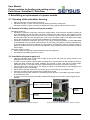
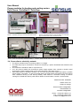
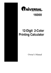
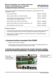
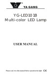
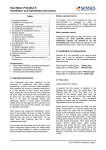
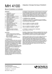
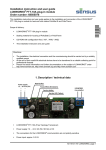
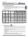
User Manual Power modules for heating and cooling meters PolluTherm / PolluStat E / PolluFlow 1. Use of the power supply modules Basically there are two different calculator housings: Calculator housing 1 (PolluTherm until 2007, PolluStat E and PolluFlow until 2010) indicated by a lid that can be opened sideways; it is closed by a black plastic latch Calculator housing 2 (PolluTherm from 2007 on, PolluTherm from 2011 on, PolluStat E and PolluFlow from 2010 on) indicated by a lid that is opened from bottom to top with two locking latches on the two bottom corners. The assignment of the modules for the calculators can be taken from the table. 1.3 Power supply modules PolluTherm Calculator Module name Power module 230 V/3V Power module 230 V/3V Power module 230V /3,6V Power module 230V /3,6V Power module 24 V/3V Power module 24 V / 3,6V Function Power supply with cable 230 V Power supply with cable 230 V Power supply with cable 230 V Power supply with cable 230 V Power supply with cable 24 V AC Power supply with cable 24 V AC Order number Back-up battery AA 68503917 hous. 1 until 2007 hous. 2 from 2007 on PolluStat E Calculator hous. 2 from 2011 on hous. 1 until 2010 hous. 2 from 2010 on X ** 68503876 X 3,6 V -JST-St. 68504998 * 68504529 68504533 hous. 2 from 2010 on X 68504679 68504532 hous. 1 until 2010 PolluFlow calculator X X X X X X X X ** 3,6 V -JST-St. 68504998 * * PolluStat E, PolluFlow and PolluTherm: when changing to power supply the back-up battery AA 3.6 V is always included in the delivery ** Retrofitting to mains power is only possible after exchanging the integrator modules to the new version 2. Safety instructions The above mentioned modules may only be used for the devices provided for in the list as otherwise the modules or the heat meter could be damaged Exchanging batteries with power supply units requires a careful handling of the batteries. Batteries must not be recharged, short-circuited, put in contact with water or exposed to temperatures of more than 80 °C Power modules for calculator housing 1 have an internal back-up battery. The same safety instructions as mentioned in the previous point apply Power modules for calculator housing 2 do not have an internal back-up battery anymore; they can be stored indefinitely Batteries and electronic waste may only be disposed at suitable collection centers for professional waste disposal The connection of network modules may only be done by persons authorized and trained for that purpose. Furthermore the generally accepted rules of technology and VDE 0100 in particular have to be observed Power module must be fed from supplies fused at 6 A protection Before exchanging a power module the existing power module has to be switched off When the power module is damaged it has to be scrapped and replaced with a new one M H 6122 INT, page 1 User Manual Power modules for heating and cooling meters PolluTherm / PolluStat E / PolluFlow 3. Retrofitting or replacement of a power module 3.1. Opening of the calculator housing Remove the lower user seal from the housing Calculator housing 1: Open housing cover by opening the black housing latch Calculator housing 2: Open housing by pressing both closing clips at the two bottom corners 3.2. Removal of battery and insert of power module Calculator housing 2: PolluStat E, PolluFlow, PolluTherm: before the supply battery is removed the calculator module has to be dismantled from the calculator. PolluTherm (delivery from 2007 to 2010): the integrator module has to be changed with a new one (from 2011 on). Unscrew only the screw from the plastic cover on the right side under the user seal (picture 3). Pull out the calculator module. The seals in the middle and on the left side may not be removed (invalidation of metrological sealing)! PolluStat E, PolluFlow, PolluTherm (from 2011 on): plug on the back-up battery AA 3,6V (68504998) to the backside of the calculator module (picture 4) (JST plug). The battery is required for date backup and short-term emergency operation in power failures. In PolluTherm (2007 to 2010) the back-up battery is soldered-on to the circuit board as standard. These modules cannot be retrofitted to mainspower supply. Calculator housing 1 and 2: Lift the battery or the power module and disconnect the output plug For disposal note safety instructions, point 2 3.3. Installation of power supply unit Plug the connection plug of the power module in the socket and insert the power module in the designated recess of the housing. In order to connect cables a spare rubber moulding has to be removed from the calculator housing 2. Guide the cable through the rubber moulding and provide a strain relief with the cable binder. Calculator housing 1: the cable has to be guided through the PG screw connection and fixed. Plug the cable of the output plug in the supply plug (due to the different pins interchanging of the power supply units is not possible). Please ensure that the cable of the connection plug is not pinched by the calculator cover. Close the calculator lid and seal with the provided self lock seal. For detection of the power module it is necessary that the device is connected to the power system for at least one minute. Through a connector encoding the M-Bus credit automatically turns off when a power supply unit is installed. Connection plug battery / power module Power module Battery: C or D Picture 1: inside view with battery, calculator housing 2 Picture 2: inside view with power module, calculator housing 2 M H 6122 INT, page 2 User Manual Power modules for heating and cooling meters PolluTherm / PolluStat E / PolluFlow Back-up battery Screw for disassembly of calculator module JST plug Calibration seal must not be removed! Picture 3: calculator housing 2: removal of calculator module Picture 4: calculator housing 2, back-up battery 3,6 V with JST plug on the back side of the calculator module Power module Output plug battery / power module Picture 5: inside view with battery calculator housing 1 Picture 6: inside view with power module calculator housing 1 3.4. Connection to electricity network The power modules have a connecting cable of 1 m length. The cable may only be connected to a 230V AC network by a person authorized and trained for that purpose. The connection should be made on a junction box. 24 V AC power modules are connected to power supply systems from controls or central control technologies. These modules must not be connected to 24 V DC direct current Since heat meters in calculator housing 1 do not count during a power supply interruption a reliable power supply is important. In case of a power failure all stored values are retained and the internal clock continues running via the back-up battery. Heat meters in calculator housing 2 continue running for a limited time after a power failure. M-Bus communication, however, can be limited. Material number: 28504962 Edition: 004-1101 Subject to change Sensus GmbH Ludwigshafen Industriestraße 16 D-67063 Ludwigshafen Phone: + 49 (0) 621 6904-1113 Fax: + 49 (0) 621 6904-1409 E-Mail: [email protected] M H 6122 INT, page 3