1
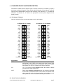
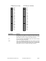
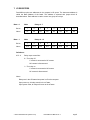
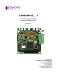
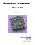
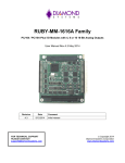
PEARL-MM 16 Relay PC/104 Module User Manual V1.2 Model PMM-S Screw terminal I/O Model PMM-P Ribbon cable I/O Copyright 2001-2004 DIAMOND SYSTEMS CORPORATION 8430-D Central Ave. Newark, CA 94560 Tel (510) 456-7800 Fax (510) 456-7878 [email protected] www.diamondsystems.com TABLE OF CONTENTS 1. DESCRIPTION ............................................................................................................................ 3 2. FEATURES ................................................................................................................................. 3 3. PEARL-MM BOARD DRAWING ................................................................................................ 4 4. I/O HEADER PINOUT AND PIN DESCRIPTION ....................................................................... 5 5. BASE ADDRESS SELECTION .................................................................................................. 7 6. RELAY SCHEMATIC.................................................................................................................. 7 7. I/O REGISTERS .......................................................................................................................... 8 8. PROGRAMMING ........................................................................................................................ 9 9. SPECIFICATIONS .................................................................................................................... 10 2001-2004 Diamond Systems Corp. Pearl-MM User Manual V1.2 Page 2 PEARL-MM-O 16 Relay Digital Output PC/104 Module 1. DESCRIPTION Pearl-MM is a PC/104 format digital I/O module designed for control of high current AC or DC loads. This module features 16 relay outputs. The 16 relay outputs are SPDT format (form C). Each relay has 3 contacts: Common, Normally Open, and Normally Closed. For safety and reliability, all relays are at their power-off state at power-up or system reset. Each relay can switch both AC and DC voltages. All outputs are isolated from the PC up to 500V AC or DC. The relays have long a rated lifetime of 100,000,000 operations and quick actuation time (4ms max operate and release). Two versions are available: Model PMM-P has pin headers for quick IDC ribbon cable connections, and model PMM-S has screw terminals on .1” centers for heavier duty wiring. 2. FEATURES ♦ ♦ ♦ ♦ ♦ ♦ ♦ 16 relay digital outputs Relays have SPDT (form C) contacts Max switching capacity 60W (DC) or 60VA (AC) Max load: 30VDC / 2A or 125VAC / 0.5A (resistive) Long lifetime relays (100,000,000 operations) 500VAC or DC isolation between board and signals High-density .1” pitch screw terminals or ribbon cable header for I/O 2001-2004 Diamond Systems Corp. Pearl-MM User Manual V1.2 Page 3 3. PEARL-MM BOARD DRAWING J1: Main PC/104 header J2: 16-bit PC/104 header J3: Connections for relays 0 - 7 J4: Connections for relays 8 - 15 J5: Base address selection NOTE: J3 and J4 are shown as pin headers (model PMM-P). The boards is also available with screw terminals in these locations (model PMM-S). 2001-2004 Diamond Systems Corp. Pearl-MM User Manual V1.2 Page 4 4. I/O HEADER PINOUT AND PIN DESCRIPTION Pearl-MM is available with two different types of output connectors, pin headers (-P option) and screw terminals (-S option). There are two identical headers on each board. J3 on the right side of the board (relative to the PC/104 connector) is for channels 0 - 7, and J4 on the left side is for channels 8 - 15. Refer to the appropriate connector pinout diagram for the board you have. 4.1 Pin Header (-P Option) Note that each pair of pins is connected together on the pin headers. J3 (Right side, pin 1 at top) 0 NO 0C 0 NC 1 NO 1C 1 NC 2 NO 2C 2 NC 3 NO 3C 3 NC 4 NO 4C 4 NC 5 NO 5C 5 NC 6 NO 6C 6 NC 7 NO 7C 7 NC Not Used 1 3 5 7 9 11 13 15 17 19 21 23 25 27 29 31 33 35 37 39 41 43 45 47 49 2 4 6 8 10 12 14 16 18 20 22 24 26 28 30 32 34 36 38 40 42 44 46 48 50 J4 (Left side, pin 1 at bottom) 0 NO 0C 0 NC 1 NO 1C 1 NC 2 NO 2C 2 NC 3 NO 3C 3 NC 4 NO 4C 4 NC 5 NO 5C 5 NC 6 NO 6C 6 NC 7 NO 7C 7 NC Not Used 8 NO 8C 8 NC 9 NO 9C 9 NC 10 NO 10 C 10 NC 11 NO 11 C 11 NC 12 NO 12 C 12 NC 13 NO 13 C 13 NC 14 NO 14 C 14 NC 15 NO 15 C 15 NC Not Used 1 3 5 7 9 11 13 15 17 19 21 23 25 27 29 31 33 35 37 39 41 43 45 47 49 2 4 6 8 10 12 14 16 18 20 22 24 26 28 30 32 34 36 38 40 42 44 46 48 50 8 NO 8C 8 NC 9 NO 9C 9 NC 10 NO 10 C 10 NC 11 NO 11 C 11 NC 12 NO 12 C 12 NC 13 NO 13 C 13 NC 14 NO 14 C 14 NC 15 NO 15 C 15 NC Not Used Signal Name N NO Definition Relay output normally open contact; this contact is disconnected when power is off or when a 0 is written to the relay’s control bit in the relay control register, and it is connected to the Out N C contact when power is on and a 1 is written to the relay’s control bit. NC (N = 0 to 15) Relay output common contact; this contact is always used with relay output connections. N NC Relay output normally connected contact; this contact is connected to the Out N C contact when power is off or when a 0 is written to the relay’s control bit in the relay control register, and it is disconnected when power is on and a 1 is written to the relay’s control bit. 4.2 Screw Terminals (-S Option) 2001-2004 Diamond Systems Corp. Pearl-MM User Manual V1.2 Page 5 J3 (Right side, pin 1 at top) 1 2 3 4 5 6 7 8 9 10 11 12 13 14 15 16 17 18 19 20 21 22 23 24 0 NO 0C 0 NC 1 NO 1C 1 NC 2 NO 2C 2 NC 3 NO 3C 3 NC 4 NO 4C 4 NC 5 NO 5C 5 NC 6 NO 6C 6 NC 7 NO 7C 7 NC J4 (Left side, pin 1 at bottom) 1 2 3 4 5 6 7 8 9 10 11 12 13 14 15 16 17 18 19 20 21 22 23 24 8 NO 8C 8 NC 9 NO 9C 9 NC 10 NO 10 C 10 NC 11 NO 11 C 11 NC 12 NO 12 C 12 NC 13 NO 13 C 13 NC 14 NO 14 C 14 NC 15 NO 15 C 15 NC Signal Name N NO Definition Relay output normally open contact; this contact is disconnected when power is off or when a 0 is written to the relay’s control bit in the relay control register, and it is connected to the Out N C contact when power is on and a 1 is written to the relay’s control bit. NC (N = 0 to 15) Relay output common contact; this contact is always used with relay output connections. N NC Relay output normally connected contact; this contact is connected to the Out N C contact when power is off or when a 0 is written to the relay’s control bit in the relay control register, and it is disconnected when power is on and a 1 is written to the relay’s control bit. 2001-2004 Diamond Systems Corp. Pearl-MM User Manual V1.2 Page 6 5. BASE ADDRESS SELECTION Refer to the Drawing of Pearl-MM on page 4 for locations of the jumper block mentioned here. Each peripheral board in the computer system must have a unique I/O address or group of addresses. Pearl-MM’s I/O address is set with jumper block J5, located at the lower left corner of the board below the PC/104 header. Seven different I/O addresses are selectable, depending on the jumper settings. The table below lists all the possible I/O addresses for Pearl-MM and their corresponding jumper settings. The default setting is 300 Hex (768 Decimal). Jumpers are installed vertically below the corresponding letters. J5: I/O Address Hex 240 280 2C0 300 340 380 3C0 Decimal 576 640 704 768 832 896 960 Jumper Settings C Out Out Out Out In In In B Out Out In In Out Out In A Out In Out In Out In Out 6. RELAY SCHEMATIC 2001-2004 Diamond Systems Corp. Pearl-MM User Manual V1.2 Page 7 7. I/O REGISTERS Pearl-MM occupies two addresses in the computer’s I/O space. The lowermost address is called the Base Address of the board. This address is selected with jumper block J4 described above. Each address is used to control one group of 8 relays. Base + 0 Write Relays 0 - 7 Bit No. 7 6 5 4 3 2 1 0 Name K7 K6 K5 K4 K3 K2 K1 K0 Base + 1 Write Relays 8 - 15 Bit No. 7 6 5 4 3 2 1 0 Name K15 K14 K13 K12 K11 K10 K9 K8 Definitions: K15 - 0 Relay output control bits: 0 = Turn relay off. C contact is connected to NC contact NO contact is disconnected 1 = Turn relay on. C contact is connected to NO contact NC contact is disconnected Notes: Relays are in the Off state when power is off to the computer. Upon power up, all relays remain in the off state. Upon system reset, all relays will return to the off state. 2001-2004 Diamond Systems Corp. Pearl-MM User Manual V1.2 Page 8 8. PROGRAMMING The following code example shows how to program the board directly. The Diamond Systems Universal Driver software also supports this board. 8.1 Turning Relays On and Off To turn a relay on, write a 1 to its corresponding bit in the output register. To turn the relay off, write a 0 to the corresponding bit. Note the following characteristics: Relays are in the Off state when power is off to the computer. Upon power up, all relays remain in the off state. Upon system reset, all relays will return to the off state. Note that you cannot individually address each bit in the output register. You must write all 8 bits at once. This means that your program must remember the contents of the output register at all times and only modify the bit(s) of the relay(s) you want to change. Here is how to control the relays. In C: int mask[8], ioaddr, i, outdata, x; ioaddr = 768; // assume default address outdata = 0; // initial value of output reg; all relays off x = 1; // used to create masks // create masks for each bit position; // mask = all 1s except for a 0 in the selected bit position for(i = 0; i <= 7; i++) { mask[i] = 255 - x; x *= 2; } // now mask[0] = 254, mask[1] = 253, ... mask[7] = 127 // turn a relay on; let’s use relay 4 (2^4 = 16) outdata = outdata | 16; // must use bitwise or, not + outp(ioaddr, outdata); // now turn relay 5 off; here we use the masks created above outdata = outdata & mask[5]; // use bitwise and to clear bit 5 outp(ioaddr, outdata); In Basic: 10 ’create masks for each bit position 20 for i = 0 to 7: mask(i) = 255 - 2^i: next i 30 ioaddr = 768 ’assume default address 40 outdata = 0 ’initial value of register at power up 50 ’turn relay 4 on 60 outdata = outdata or 16 ’must use or, not + 70 out ioaddr, outdata 80 ’turn relay 5 off 90 outdata = outdata and mask(5) ’clear bit 5, protect other bits 100 out ioaddr, outdata 2001-2004 Diamond Systems Corp. Pearl-MM User Manual V1.2 Page 9 9. SPECIFICATIONS Relay Outputs Outputs: 16 relays Relay type: SPDT (Form C) Maximum voltage/current: DC outputs: 30VDC / 2A AC outputs: 250VAC / 0.5A resistive Max switching capacity: 60W (DC), 60VA (AC) Max operating voltage: 220VDC, 250VAC Contact resistance: 100mΩ max Relay lifetime: 100,000,000 operations Actuation time: Operate 4ms max, release 4ms max General Connection headers: -P version: -S version: Isolation: Power supply: Current consumption: Operating temperature: Operating humidity: PC/104 bus: 2001-2004 Diamond Systems Corp. 50-position (2x20) .025” square pin header on .1” centers; Mates with standard ribbon cable (IDC) connectors 24-position screw terminals on .1” centers; terminals accept 14-30 gauge wiring 500VDC or AC, channel to channel and board to output +5VDC ±10% 100mA typical, all relays off; Additional 20mA per activated relay -40 to +85oC 5% to 95% noncondensing 8 bit main bus header is installed and used. 16-bit extension header footprint is present for optional passthrough use; however no signals on this header are used on Pearl-MM. Pearl-MM User Manual V1.2 Page 10