1
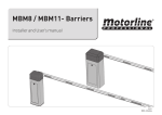
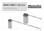
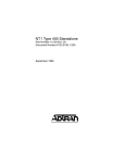
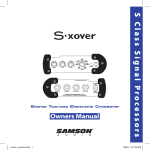
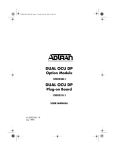
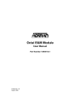
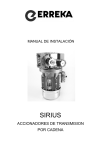
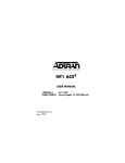
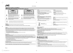
Quad FXOVoice Module User Manual Part Number 1175407L1 61175407L1-1A February 2000 901 Explorer Boulevard P.O. Box 140000 Huntsville, AL 35814-4000 (256) 963-8000 © 2000 ADTRAN, Inc. All Rights Reserved. Printed in U.S.A. Federal Communications Commission (FCC) Radio Frequency Interference Statement This equipment has been tested and found to comply with the limits for a Class A digital device, pursuant to Part 15 of the FCC Rules. These limits are designed to provide reasonable protection against harmful interference when the equipment is operated in a commercial environment. This equipment generates, uses, and can radiate radio frequency energy and, if not installed and used in accordance with the instruction manual, may cause harmful interference to radio frequencies. Operation of this equipment in a residential area is likely to cause harmful interference in which case the user will be required to correct the interference at his own expense. Shielded cables must be used with this unit to ensure compliance with Class A FCC limits. Change or modifications to this unit not expressly approved by the party responsible for compliance could void the user’s authority to operate the equipment. Canadian Emissions Requirements This digital apparatus does not exceed the Class A limits for radio noise emissions from digital apparatus as set out in the interference-causing equipment standard entitled “Digital Apparatus,” ICES-003 of the Department of Communications. Cet appareil numerique respecte les limites de bruits radioelectriques applicables aux appareils numeriques de Class A prescrites dans la norme sur le materiel brouilleur: “Appareils Numeriques,” NMB-003 edictee par le Ministre des Communications. Warranty and Customer Service ADTRAN will replace or repair this product within five years from the date of shipment if the product does not meet its published specification, or if it fails while in service. For detailed warranty, repair, and return information, refer to the ADTRAN Equipment Warranty and Repair and Return Policy Procedure (see the last page of this manual). A return material authorization (RMA) is required prior to returning equipment to ADTRAN. For service, RMA requests, or more information, see the last page of this manual for the toll-free contact number. iii Limited Product Warranty ADTRAN warrants that for five (5) years from the date of shipment to Customer, all products manufactured by ADTRAN will be free from defects in materials and workmanship. ADTRAN also warrants that products will conform to the applicable specifications and drawings for such products, as contained in the Product Manual or in ADTRAN's internal specifications and drawings for such products (which may or may not be reflected in the Product Manual). This warranty only applies if Customer gives ADTRAN written notice of defects during the warranty period. Upon such notice, ADTRAN will, at its option, either repair or replace the defective item. If ADTRAN is unable, in a reasonable time, to repair or replace any equipment to a condition as warranted, Customer is entitled to a full refund of the purchase price upon return of the equipment to ADTRAN. This warranty applies only to the original purchaser and is not transferable without ADTRAN's express written permission. This warranty becomes null and void if Customer modifies or alters the equipment in any way, other than as specifically authorized by ADTRAN. EXCEPT FOR THE LIMITED WARRANTY DESCRIBED ABOVE, THE FOREGOING CONSTITUTES THE SOLE AND EXCLUSIVE REMEDY OF THE CUSTOMER AND THE EXCLUSIVE LIABILITY OF ADTRAN AND IS IN LIEU OF ANY AND ALL OTHER WARRANTIES (EXPRESSED OR IMPLIED). ADTRAN SPECIFICALLY DISCLAIMS ALL OTHER WARRANTIES, INCLUDING (WITHOUT LIMITATION), ALL WARRANTIES OF MERCHANTABILITY AND FITNESS FOR A PARTICULAR PURPOSE. SOME STATES DO NOT ALLOW THE EXCLUSION OF IMPLIED WARRANTIES, SO THIS EXCLUSION MAY NOT APPLY TO CUSTOMER. In no event will ADTRAN or its suppliers be liable to Customer for any incidental, special, punitive, exemplary or consequential damages experienced by either Customer or a third party (including, but not limited to, loss of data or information, loss of profits, or loss of use). ADTRAN is not liable for damages for any cause whatsoever (whether based in contract, tort, or otherwise) in excess of the amount paid for the item. Some states do not allow the limitation or exclusion of liability for incidental or consequential damages, so the above limitation or exclusion may not apply to Customer. iv Table of Contents List of Figures ....................................................................................................................................................vii Chapter 1 Introduction .............................................................................................................................. 1-1 Quad FXO Voice Module Overview .............................................................................................................. 1-1 Functional Description.............................................................................................................................. 1-2 Features ....................................................................................................................................................... 1-2 QUAD FXO Voice Module Specifications ..................................................................................................... 1-3 Chapter 2 Installation ................................................................................................................................ 2-1 Before Installing the Quad FXO Voice Module ............................................................................................ 2-1 Shipping Contents ..................................................................................................................................... 2-1 Installing the Quad FXO Voice Module ........................................................................................................ 2-1 Wiring ................................................................................................................................................................. 2-2 TA 850.......................................................................................................................................................... 2-2 Chapter 3 Operation .................................................................................................................................. 3-1 Overview ............................................................................................................................................................ 3-1 LED Status .................................................................................................................................................. 3-1 Testing ................................................................................................................................................................ 3-1 Self-Test ....................................................................................................................................................... 3-1 Initiated Tests ............................................................................................................................................. 3-1 Methods of operation ....................................................................................................................................... 3-2 Terminal Menu Structure................................................................................................................................. 3-2 Quad FXO Voice Module Menu Options ...................................................................................................... 3-3 Prt ................................................................................................................................................................ 3-3 Mode ........................................................................................................................................................... 3-3 Loop Start ............................................................................................................................................ 3-3 Ground Start ....................................................................................................................................... 3-3 DPT ...................................................................................................................................................... 3-3 TX (dB) ........................................................................................................................................................ 3-3 RX (dB) ....................................................................................................................................................... 3-3 Svc Mode .................................................................................................................................................... 3-3 Quad FXO Voice Module Test Options ......................................................................................................... 3-4 Prt ................................................................................................................................................................ 3-4 Test .............................................................................................................................................................. 3-4 Digital Net Loopback Test ................................................................................................................ 3-4 Network On-Hook/Off-Hook Test ................................................................................................. 3-4 1004 Hz - 0dbm0 Tone Generation Test ......................................................................................... 3-4 Test Status .................................................................................................................................................. 3-4 Quad FXO Voice Module Status Options...................................................................................................... 3-4 TA 850 Features Used with Quad FXO Voice Module Options ................................................................ 3-4 61175407L1 Quad FXO Voice Module User Manual v Table of Contents Factory Restore ........................................................................................................................................... 3-4 Index ...........................................................................................................................................................Index-1 vi Quad FXO Voice Module User Manual 61175407L1 List of Figures Figure 1-1. Quad FXO Voice Module ........................................................................................................... 1-1 Figure 2-1. Connector Pin Assignments....................................................................................................... 2-2 Figure 3-1. Quad FXO Voice Module Menu Options ................................................................................ 3-3 61175407L1 Quad FXO Voice Module User Manual vii List of Figures viii Quad FXO Voice Module User Manual 61175407L1 Chapter 1 Introduction QUAD FXO VOICE MODULE OVERVIEW The Quad FXO Voice Module (see Figure 1-1) is for use in the Total Access 750/850/1500 (TA 750/850/1500) platforms to provide analog voice extension. The Quad FXO resides in the TA chassis that is next to or close to the customer’s telephone and is usually located on the customer’s premises. This unit can be used in conjunction with the TA 750/850/1500 FXS Voice Module, which resides in the TA 750/850/1500 that is located next to the Central Office switch. FXO 1175407L1 BUSY 1 2 3 4 Figure 1-1. Quad FXO Voice Module If TR-08 signaling format is not readily available at the CO switch, both FXO and FXS access modules can be used for deployment. The TA 850 at the CO will combine a number of analog lines and then multiplex them for T1 transmission to the TA 850 at the customer premise. 61175407L1 Quad FXO Voice Module User Manual 1-1 Chapter 1. Introduction Functional Description The Quad FXO Voice Module installs in any available option slot in the TA 850 chassis. You can view the status of the module itself, as well as the circuits to which it interfaces, from the TA 850 front panel. Additional status information is available via the terminal menus, accessible through either a VT-100 terminal connected to the TA 850 control port or via a Telnet session established through the Base Unit’s Ethernet port. Features Features of the Quad FXO Voice Module include: 1-2 • Four voice ports • Automatic short loop provisioning • µ-law encoding and decoding • Support for Ground start, loop start, and TR-08 signaling • Long loop capability -- 1200 ohms including telephone set (16 kfeet @ 24 AWG) • Hot-swappable • V.90 Modem compliant • Support for CLASS features such as Caller ID • Transmit attenuation setting of 0 to -9 dB • Receive attenuation setting of 0 to -9 dB • Selectable 600 ohm, 900 ohm, 600 ohm + 2.16µF, or 900 ohm + 2.16µF 2-wire VF interface • NEBS Level 3 and UL 1950 compliant • Extended temperature range of -40 to +65 °C Quad FXO Voice Module User Manual 61175407L1 Chapter 1. Introduction QUAD FXO VOICE MODULE SPECIFICATIONS The Quad FXO Voice Module conforms to the following specifications: ELECTRICAL SPECIFICATIONS Power 6 Watts (off hook) Loop Current 23 mA nominal 20 mA minimum Loop Resistance 1200 ohms nominal/1650 ohms maximum* (900 ohms/1350 ohms - line, 300 ohms - phone) Loop Length 16 kfeet Terminating Impedance User selectable 900 ohm + 2.16µF, 600 ohm + 2.16µF, 900 ohm, and 600 ohm Return Loss 900 ohm + 2.16µF, ERL > 28 dB, SRL > 20 dB Trans Hybrid Loss 900 ohm + 2.16µF, ERL > 28 dB, SRL > 20 dB Longitudinal Balance 200, 500, and 1000 Hz: > 58 dB min., > 63 dB avg. 3000 Hz: > 53 dB min., > 58 dB avg. Frequency Response 300 to 3400 Hz: -0.5 and 1.0 dB Idle Channel Noise < 20 dBrnC Signal-to-Distortion Ratio 0 to -30 dBm0: > 33 dB -30 to -40 dBm0: > 27 dB -40 to -45 dBm0: > 22 dB PHYSICAL SPECIFICATIONS Dimensions 3 1/4" H x 10" D Weight 1 lb. ENVIRONMENTAL SPECIFICATIONS Operating Temperature -40 to 64 °C Storage Temperature -40 to 70 °C Relative Humidity Up to 95% noncondensing *Measured with -48 VDC input, 20 mA loop current 61175407L1 Quad FXO Voice Module User Manual 1-3 Chapter 1. Introduction 1-4 Quad FXO Voice Module User Manual 61175407L1 Chapter 2 Installation BEFORE INSTALLING THE QUAD FXO VOICE MODULE Carefully unpack and inspect the Quad FXO Voice Module for shipping damages. If you suspect damage occurred during shipping, file a claim immediately with the carrier and then contact ADTRAN Technical Support (see the last page of this manual for pertinent information). If possible, keep the original shipping container for returning the Quad FXO Voice Module for repair or for verification of shipping damage. Shipping Contents The ADTRAN shipment includes the following items: • Quad FXO Voice Module • Quad FXO Voice Module User Manual (Insert into the TA 850 User Manual.) INSTALLING THE QUAD FXO VOICE MODULE The following Step/Action table describes the actions required to install the Quad FXO Voice Module. Instructions for Installing the Quad FXOVoice Module 61175407L1 Step Action 1 Hold the Quad FXO Module by the faceplate while supporting the bottom side. 2 Align the module edges to the guide grooves for the designated slot. 3 Insert the module until the edge connector seats firmly into the backplane. 4 Lock the unit in place by pushing in on the locking lever. Quad FXO Voice Module User Manual 2-1 Chapter 2. Installation Instructions for Installing the Quad FXOVoice Module (Continued) Step Action 5 Connect the cables to the associated device(s). 6 Complete installation of remaining modules and Base Unit as specified in the Installation chapter of the TA 850 User Manual. WIRING TA 850 A single 50-pin male amphenol connector on the rear of the TA 850 chassis provides the interconnect wiring for the four analog circuits on each access module. Figure 2-1 shows the pinout connection. 25 50 24 49 23 22 21 20 48 47 46 45 19 44 18 43 17 16 42 41 15 40 14 39 13 38 12 37 11 36 10 35 9 34 8 33 7 32 6 31 5 30 4 29 3 28 2 27 1 26 P P P Slot 6 P P P P Slot5 P P P P Slot 4 P P P P Slot 3 P P P P Slot 2 P P P P P Slot 1 NC T R T R T R T R T R T R T R T R T R T R T R T R T R T R T R T R T R T R T R T R T R T R T R T R Circuit 4 Circuit 3 Circuit 2 Circuit 1 Circuit 4 Circuit 3 Circuit 2 Circuit 1 Circuit 4 Circuit 3 Circuit 2 Circuit 1 Circuit 4 Circuit 3 Circuit 2 Circuit 1 Circuit 4 Circuit 3 Circuit 2 Circuit 1 Circuit 4 Circuit 3 Circuit 2 Circuit 1 50 PIN AMP RECEPTACLE Figure 2-1. Connector Pin Assignments 2-2 Quad FXO Voice Module User Manual 61175407L1 Chapter 3 Operation OVERVIEW The Quad FXO Voice Module goes operational upon insertion into an active TA 750/850/1500 chassis. Once a module is inserted, the user must map an FXO port to a network port for proper operation. Refer to the TA 850 User Manual Channel Bank chapter (DS0 mapping section) for information. LED Status After the initialization sequence, faceplate LEDs show the status of the analog service for each customer loop, as follows: Off On Hook Flashing Ringing On Off Hook (Busy) TESTING Self-Test A self-test is performed on the Quad FXO Voice Module when it is inserted into an active TA 850 chassis. The test verifies proper operation of critical circuits. If the test is successful, all four LEDs turn on in a predefined sequence, the unit is placed in service, and the LEDs then return to normal operation showing current status of the FXO. Initiated Tests Other tests conducted on the Quad FXO Voice Module are initiated via the screen menus and VT 100 terminal. (See Quad FXO Voice Module Test Options on page 3-4 for more information.) 61175407L1 Quad FXO Voice Module User Manual 3-1 Chapter 3. Operation METHODS OF OPERATION You can control and configure the Quad FXO Voice Module from the following sources: • The terminal menus, allowing detailed configuration, status, and diagnostics • SNMP, primarily for reporting alarm conditions and system status The remainder of this section describes the menu items presented when managing the Quad FXO Voice Module via the terminal menu. Access the terminal menu using either a VT-100 terminal attached to the TA 850 Base Unit’s control port or a Telnet session established through the Base Unit’s Ethernet port. The TA 850 User Manual provides detailed instructions on the operation of each of these management approaches. The factory default password is PASSWORD. It can be changed to a userspecified password. TERMINAL MENU STRUCTURE The TA 850 uses a hierarchical menu structure to provide access to all of its features. The top-most menu level leads to submenus which are grouped by functionality. All menu items display in the terminal window. To access the Quad FXO Voice Module, activate the MODULES menu. Refer to the TA 850 User Manual for detailed instructions on navigating through the terminal menu. From the MODULES menu, select the QUAD FXO menu, and then press Enter to access the features of the Quad FXO card. 3-2 Quad FXO Voice Module User Manual 61175407L1 Chapter 3. Operation QUAD FXO VOICE MODULE MENU OPTIONS Figure 3-1 shows the menu options available for the Quad FXO Voice Module. The following sections describe these options. Figure 3-1. Quad FXO Voice Module Menu Options PRT Identifies the port involved. MODE Options are given below. LOOP START Sets the port to use FXO loop start signalling on the T-span and loop start supervision on the analog 2-wire interface. GROUND START Sets the port to use FXO ground start signalling on the T-span and ground start supervision on the analog 2-wire interface. DPT Sets the port to use Dial Pulse signalling to terminate dialed numbers. TX (DB) Sets the Tx direction transmit level points. The transmission level is indicated in dBm. Range is from 0 to 9.9 dBm. Default is 6.0. RX (DB) Sets the Rx direction transmit level points. The transmission level is indicated in dBm. Range is from 0 to 9.9 dBm. Default is 3.0. SVC MODE Indicates whether the module is IN SERVICE or OUT OF SVC. This does not indicate whether the port has been mapped. For proper operation, the port must be mapped using the DS0 MAPS menu. 61175407L1 Quad FXO Voice Module User Manual 3-3 Chapter 3. Operation QUAD FXO VOICE MODULE TEST OPTIONS PRT Identifies the port involved. TEST To initiate a module test, scroll to the TEST column and press Enter. Options are detailed below. DIGITAL NET LOOPBACK TEST The Digital Net Loopback Test is used to loop back DS0 data coming from the network for each channel. Received data is latched In on the appropriate receive time slot on the receive bus. This data is then placed on the transmit bus in the unit’s transmit time slot. NETWORK ONHOOK/OFFHOOK TEST The Network On-Hook/Off-Hook Test is used to test signaling sent to the network by the unit. When On-Hook Test is selected, On-Hook signaling is sent to the network. When Off-Hook Test is selected, Off-Hook signaling is sent to the network. The customer loop is forced On-Hook while this test is active. 1004 HZ 0DBM0 TONE GENERATION TEST The 1004 Hz - 0dbm0 Tone Generation Test is used to send DRS signal on the receive path to the loop. The loop receive level that should be received is determined by the following equation: TEST STATUS Receive Level = 0 dB - Attenuation Tells whether a test is in progress. QUAD FXO VOICE MODULE STATUS OPTIONS The transmit and receive signalling bits are shown in the STATUS menu of the Quad FXO module. TA 850 FEATURES USED WITH QUAD FXO VOICE MODULE OPTIONS Two additional TA 850 menu items can operate in conjunction with the Quad FXO Voice Module: FACTORY RESTORE and RUN SELFTEST. Factory Restore You can restore the factory default settings for an Quad FXO Voice Module by pressing F while the cursor is over the SLT number (this action restores the factory settings for all of the module options), while the cursor is over the PRT number (this action restores the factory settings for the port), or while the cursor is over an individual field (this action restores factory settings for the particular field only). 3-4 Quad FXO Voice Module User Manual 61175407L1 Index Numerics N 1004 Hz - 0dbm0 tone generation test 3-4 network on-hook/off-hook test 3-4 C O connectors 1-3 customer service iii operation 3-1 overview 1-1 operation 3-1 D description 1-2 dial pulse signalling 3-3 digital net loopback test 3-4 DPT 3-3 P power connection connection 2-2 prt 3-3 F Q factory restore 3-4 features 1-2 TA 850 3-4 Quad FXO module description 1-2 features 1-2 installing 2-1 operation 3-1 overview 1-1 specifications 1-3 G ground start 3-3 I Installing 2-1 installing Quad FXO module 2-1 introduction 1-1 L LEDs 3-1 loopstart 3-3 M menu structure 3-2 terminal menu structure 3-2 menu options 3-3 mode 3-3 61175407L1-1 R restore 3-4 RMA requests iii RX (dB) 3-3 S service iii specifications 1-3 status options 3-4 svc mode 3-3 T TA 850 features 3-4 terminal menu 3-2 terminal menu structure 3-2 test options 3-4 test status 3-4 testing 3-1 Quad FXO Voice Module User Manual Index-1 Index tests initiated tests 3-1 self-test 3-1 TX (dB) 3-3 Index-2 W warranty iii, iv wiring 2-2 Quad FXO Voice Module User Manual 61175407L1-1 Product Support Information Presales Inquiries and Applications Support Please contact your local distributor, ADTRAN Applications Engineering, or ADTRAN Sales: Applications Engineering (800) 615-1176 Sales (800) 827-0807 Post-Sale Support Please contact your local distributor first. If your local distributor cannot help, please contact ADTRAN Technical Support and have the unit serial number available. Technical Support (888) 4ADTRAN Repair and Return If ADTRAN Technical Support determines that a repair is needed, Technical Support will coordinate with the Customer and Product Service (CAPS) department to issue an RMA number. For information regarding equipment currently in house or possible fees associated with repair, contact CAPS directly at the following number: CAPS Department (256) 963-8722 Identify the RMA number clearly on the package (below address), and return to the following address: ADTRAN Customer and Product Service 6767 Old Madison Pike Building #6 Suite 690 Huntsville, Alabama 35807 RMA # _____________