1
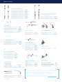
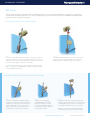
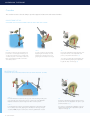
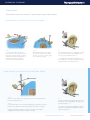
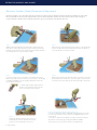
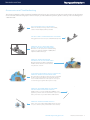
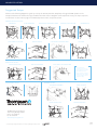
Thompson
Retractor
User Manual
FRAMES:
•QUICK FRAME
•BILATERAL FRAME
SET UPS:
•GENERAL
•VASCULAR
•TRANSPLANT
•UROLOGY
•GYNECOLOGY
Uncompromised Exposure.
PRODUCT INDEX
ELITE II RAIL CLAMPS
11" (25cm) Tall with 1 1/2" Cam Joint
41902ACS
18" (45cm) Tall with 1 1/2” Cam Joint
41902AC
18" (45cm) Tall with 2 1/2” Cam Joints
41903AC
22" (55cm) Tall with 1 1/2” Cam Joint
41904AC
22" (55cm) Tall with 2 1/2” Cam Joints
41905AC
13” - 22” (33cm - 55cm)
26" (65cm) Tall with 1 1/2” Cam Joint
41906AC
AHRC with 1 Adjustable Cam Joint
41902ARC
26" (65cm) Tall with 2 1/2” Cam Joints
41907AC
AHRC with 2 Adjustable Cam Joints
41903ARC
ADJUSTABLE HEIGHT RAIL CLAMPS
Non-Angling
CROSSBARS
Angling
Crossbar with 2 Cam Joints 24" (11" x 13")
41900BC
Crossbar with 2 Adjustable Cam Joints 24"
41900BAC
Crossbar with 2 Cam Joints 24" (8" x 16")
41900BCW
Angled Arm 24" (11" x 13")*
44124W
*May be used as a crossbar (see below for more options)
Serrated
CAM I SLIDE-ON JOINTS
CAM II HANDLES
Clip-on 8" (non-angling)
42126WH
Cam I Serrated Slide-on Joint
42112C
Clip-on 8" Angling
42126WA
Cam I Slide-on Joint
42110C
BILATERAL CROSSBARS
Non-Angling
Bilateral Crossbar 7 1/4" x 13 1/2" x 7 1/4"
41900F
Bilateral Crossbar Hinged 11" x 8 1/2" x 11"
41900H
Bilateral Crossbar Hinged 14" x 10" x 14"
41900HL
MICRO-ADJUSTABLE II
NON-ANGLING HANDLES
Clip-on 10 3/4"
45006STC
Clip-on 8 3/4"
45007STC
Clip-on 10 3/4" Bariatric
45006BTC
Clip-on 8 3/4" Bariatric
45007BTC
TABLE ADAPTER
Jackson Spine Frame Adapter
41927
ANGLED LATERAL ARMS
26" (6" x 20") (15cm x 50cm)
44126
24" (11" x 13") (28cm x 33cm)
44124W
24" (8" x 16") (20cm x 40cm)
44124N
18" (8" x 10") (20cm x 25cm)
44118N
12" (6" x 6") (15cm x 15cm)
44014S
Angling
MICRO-ADJUSTABLE II
ANGLING HANDLES
STRAIGHT ARMS
Clip-on Angling 10"
45006CA
RAIL EXTENDER
Rail Extender 15" Single Clamp
5844
41917
41929
Straight Arm 12" (30cm)
44012N
Clip-on Angling 7 3/4"
45007CA
Rail Extender 14" long with 2 1/4" offset
Dual Clamp (helpful for obese patients)
Straight Arm 20" (50cm)
44120N
Slide-on Angling 7 3/4"
45007STA
Rail Extender 22"Dual Clamp
Straight Arm with 1 Cam Joint 20" (50cm)
44120C
Please use this Product Index to reference Thompson Retractor Frame components shown
in this manual. These products can be combined to create the Quick Frame or Bilateral
Frame, or can be used to modify an existing frame. Thompson Retractor can also create
custom frame components to meet any unique surgical needs. Additionally, we offer
components that are compatible with Omni, Bookwalter or Synthes products.
EXTENSION ARMS
Extension Arm 12" with Cam Latch Joint
44014LC
Hinged Extension Arm 12" x 12"
44115
2 USER MANUAL
Additional product information can be found at our web site at www.thompsonsurgical.com
and can be ordered by calling Thompson Surgical at 800.227.7543.
ASSEMBLING THE FRAME
Rail Clamp
The rail clamp is the base of the Quick Frame and Bilateral Frame; it secures to standard OR tables to support the crossbar and/
or frame arms. Rail clamps may have one or two joints depending on your preferred use. If using an Adjustable Height Rail Clamp,
please see bottom of page for instruction.
ELITE II RAIL CLAMP SET UP INSTRUCTIONS:
STEP 1
To secure one Elite Rail Clamp to the table, be sure the jaws of the rail
clamp are completely open by turning the knob at the top of the rail
clamp. Once open, secure the rail clamp by placing the open rail clamp
jaw over the sterile drape on either side of the table.
STEP 2
To tighten the Elite Rail Clamp to the table, turn the knob
at the top of the rail clamp and utilize the attached two
hanging handles for added leverage when needed.
CAUTION: If the patient is obese, avoid compressing the ulnar nerve.
When necessary, use a wider OR table or add to the width of the table
using our Rail Extender (41917).
ADJUSTABLE HEIGHT RAIL CLAMP SET UP INSTRUCTIONS:
STEP 1
To secure the Adjustable Height Rail Clamp to
the table, be sure the jaws of the rail clamp are
completely open by turning the knob at the top
of the rail clamp. Once open, secure the rail
clamp by placing the open rail clamp jaw over
the sterile drape on either side of the table.
STEP 2
To tighten to the Adjustable
Height Rail Clamp to the table,
turn the knob at the top of the
rail clamp and utilize the attached
four hanging handles for added
leverage when needed.
STEP 3
A Adjust the height of the Adjustable Height Rail
Clamp post by pushing down on the grooved sleeve
and sliding the post up or down to one of the five
set heights marked by the grooves on the post.
B With the post positioned at the desired height,
release the grooved sleeve to lock the setting.
www.thompsonsurgical.com
THOMPSON RETRACTOR 3
ASSEMBLING THE FRAME
Crossbar
The crossbar secures to the rail clamp to provide support for frame arms and retractor handles.
QUICK FRAME SET UP:
CROSSBAR SETUP INSTRUCTIONS FOR USE WITH ONE RAIL CLAMP
A
B
STEP 1
Insert the crossbar into the rail clamp and
position the crossbar approximately 3 to 5
cm above the patient. Prior to inserting the
crossbar, the joint on rail clamp needs to be
fully open by flipping handle out into the
‘unlocked’ position.
STEP 2
Lock the crossbar to the rail clamp
by flipping the rail clamp cam joint
handle into ‘locked’ position and
grasping the rail clamp for leverage.
TIP:
If using the adjustable height rail clamp, turn
the pressure knob on the adjustable cam
joint to your preferred resistance. (A)
To lock the crossbar, flip the adjustable cam
joint handle while grasping the adjustable
height rail clamp for leverage. (B)
BILATERAL SET UP:
CROSSBAR SETUP INSTRUCTIONS FOR USE WITH TWO RAIL CLAMPS
1
A
2
B
STEP 1
Insert the bilateral crossbar into the top joint of the rail clamp, making sure
joints are fully open (‘unlocked’ position) on either side of the OR table.
Adjust the bilateral crossbar’s height 8 to 10 cm over the patient.
STEP 2
Lock the bilateral crossbar to rail clamp by flipping the rail clamp handle
into ‘locked’ position and grasping the rail clamps for leverage. A rigid
crossbar (41900F) may be used in place of the hinged bilateral crossbar.
4 USER MANUAL
TIP:
If using the adjustable height rail clamp, turn the
pressure knob on the adjustable cam joint to your
preferred resistance. (A)
To lock the crossbar, flip the adjustable cam joint
handle while grasping the adjustable height rail
clamp for leverage. (B)
ASSEMBLING THE FRAME
Frame Arms
The frame arms secure to the crossbar or to the rail clamp to support retractor handles.
FRAME ARM SET UP INSTRUCTIONS FOR QUICK FRAME:
A
B
STEP 1
Insert the frame arms into the cam
joints on the crossbar and position the
frame arms over the patient’s body low
and wide around the operating space.
All joints should be in ‘unlocked’
position when inserting frame arms.
STEP 2
With the frame arm positioned, flip
the cam joint handle into ‘locked’
position. To secure each arm, grasp
the crossbar for leverage.
TIP:
If locking the frame arm to an adjustable crossbar,
turn the pressure knob on the adjustable cam
joint to your preferred resistance. (A)
To lock the frame arm, flip the adjustable cam
joint handle into ‘locked’ position while grasping
the adjustable crossbar for leverage. (B)
FRAME ARM SET UP INSTRUCTIONS FOR BILATERAL FRAME:
1
A
2
B
STEP 1
Insert one or two frame arms into the bottom joint on the rail clamp and
position around the incision.
STEP 2
Lock the frame arms to the rail clamp by flipping the rail clamp’s cam joints
handle into ‘locked’ position while grasping the rail clamp for leverage.
If using an adjustable height rail camp, lock the frame arms with the
adjustable cam joints as shown in the previous steps.
TIP:
If using the adjustable height rail clamp, turn the
pressure knob on the adjustable cam joint to your
preferred resistance. (A)
To lock the crossbar, flip the adjustable cam joint
handle while grasping the adjustable height rail
clamp for leverage. (B)
www.thompsonsurgical.com
THOMPSON RETRACTOR 5
RETRACTOR HANDLES AND BLADES
Retractor Handles, Blade Placement & Adjustment
Retractor handles lock to the frame arms and crossbar to support retractor blades. Retractor handles are available in Cam II and
Micro-Adjustable II varieties with angling handle options. Micro-adjustable handles provide retraction when extra leverage is
needed. Retractor blades can be infinitely adjusted to give you unlimited, multi-planed exposure.
STEP 1
With the retractor handle in the unlocked position, clip the joint to the
frame arm or crossbar, by pushing the joint down over the bar. Keep the
bulk of the joint positioned on the outside of the frame. Flip the handle to
the ‘locked’ position to secure the retractor handle.
STEP 2
After selecting a retractor blade, press the button on the head of the
retractor handle and insert the blade nipple. Release the button to
secure the blade to the retractor handle.
STEP 3
Position the blade in the incision with your hand and retract back.
When using angling retractor handles, use your fingers or the Angling
Head Wrench (43032) to turn the angling adjustment and tow the
retractor blade as desired.
STEP 4
While retracting the blade, utilize the spring of the frame to maintain
the desired amount of retraction. To do this, apply counter-pressure
to the frame arm or Crossbar that the retractor handle is attached to.
TIP: Blades supported by angling retractor
handles can be infinitely positioned in the
incision to provide precise retraction.
STEP 5
Holding the blade and frame in place, have your
assistant flip the retractor handle to the locked
position to secure the blade in the incision.
6 USER MANUAL
BLADE & RETRACTOR HANDLE ADJUSTMENT TIPS
• To retract a blade after a Micro-Adjustable II Angling Retractor Handle
has been locked, turn the knob to utilize microadjustable retraction (as
shown above).
• To angle a locked & retracted blade, an angling head wrench may be
desired for increased leverage. Angling Head Wrench (43032)
To prevent tissue necrosis release retractors every 20 minutes.
TROUBLESHOOTING
Accessories and Troubleshooting
The Thompson Retractor offers exceptional versatility and can be set up to meet all your exposure needs. Please use the following
accessories and troubleshooting tips for easiest set up. If you have additional questions, please contact your account manager at
1-800-227-7543.
RAIL CLAMP DOES NOT FIT ON OR TABLE
Call for an extender, or if using a Jackson Frame Table,
a Jackson Frame Adapter (41927) is available.
THE RAIL CLAMP IS INTERFERING WITH THE PATIENT
If a bigger bed cannot be used, use our Rail Extender (41917).
HOW CAN I ADJUST THE BLADE ANGLE
WITHOUT RELEASING THE RETRACTION?
When there is a lot of pressure on the blade during
retraction, an Angling Head Wrench (43032) will be
helpful for additional leverage.
HOW CAN I OBTAIN RETRACTION
PERPENDICULAR TO THE FRAME ARMS?
Our patented Cam II and Micro-Adjustable II
Handles allow the blade to swivel and retract
in any direction as shown.
IF MY RETRACTOR HANDLES ARE FULLY RETRACTED,
HOW CAN I OBTAIN FURTHER RETRACTION?
Unlock the retractor handles to release the tension and adjust
the frame arms by spreading them low and wide from the
incision. If further retraction is needed, please contact your
account manager; longer handles may be necessary.
HOW CAN I ADD MORE ROOM TO THE FRAME
FOR ADDITIONAL RETRACTOR HANDLES?
Additional arms, such as the Straight Arm (44012N), can be
applied to your frame and connected with the one piece cam
frame joints. Please see product index for additional arms.
HOW CAN I INCREASE FRAME STABILITY?
Frame can be enclosed by adding additional arms using the
one piece cam frame joints (as described in above solution).
Serrated
www.thompsonsurgical.com
THOMPSON RETRACTOR 7
SUGGESTED SETUPS
Suggested Setups
Please use the following diagrams to guide your set up for General, Vascular, Transplant, Urology and GYN operations. The
Thompson Retractor has unlimited set up possibilities and each of these diagrams can be adjusted to meet your unique exposure
needs. Please see the index on page 2 for additional pictures of the components shown.
GENERAL/VASCULAR SETUPS:
ABDOMINAL
UPPER ABDOMINAL
LYMPH NODE DISSECTION
RADIOLUCENT ANTERIOR LUMBAR
MINIMAL ACCESS
CAROTID/SMALL INCISION
LIVER TRANSPLANT/RESECTION
COLON/RECTAL
PEDIATRIC
TRANSPLANT SETUPS:
KIDNEY TRANSPLANT
LIVER TRANSPLANT/RESECTION
MINI NEPHRECTOMY
Liver transplant/
resection systems may
be modified as needed
with different sized
frame arms & crossbars.
Additionally, rail clamps
may be staggered for a
diagonal setup.
GYNECOLOGY SETUPS:
UROLOGY SETUPS:
ABDOMINAL UROLOGY
KIDNEY TRANSPLANT
HARRIS PERINEAL
MINI NEPHRECTOMY
10170 East Cherry Bend Road
Traverse City, Michigan 49684
phone: 231.922.0177
fax: 231.922.0174
www.thompsonsurgical.com
© 2013 Thompson Surgical Instruments, Inc. Traverse City, Michigan. Printed in U.S.A.
0297
Rev B
1211613
um1213