1
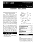
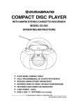
Nauticharger
Smart Charger 12V 25A - 3 output
User manual - English
Nautimarket srl - Nauticharger Division -Via San Giorgio – 33050 Carlino (UD)Tel: +39 0431 687182-83 Fax: +39 0431 687013
www.nauticharger.com
Read these instructions carefully before the installation and commissioning and keep them in a safe place. Pass it on to the buyer in case
of the further sale of the system.
Update: Dec 2006
Standard accessory list
Temperature compensation cable and plug.
2.0 General safety information
2.1 General safety
* Use the smart battery charger only for its use as intended (batterycharger)
* Use the smart battery charger only in well ventilated rooms.
* Always interrupt the power supply when doing repair work on the unit.
Warning!
Batteries contain aggressive acids.
Avoid the contact with the battery fluid agent. If a contact with battery fluid agent should occur, then rinse the affected parts of the body or clothing etc. with
plenty cold water. lt is imperative to seek medical treatment from a doctor with injuries caused by acid.
1. Do NOT expose lead-acid batteries to a Iit cigarette, sparks or flames because they produce flammable gasses and could explode.
2. Never try to charge a frozen battery. There is the danger of explosion! In this case, place the battery at a frost-resistant location and wait until the
battery has adapted to the ambient temperature. Only then is the charging process started.
3. Store the smart battery charger in a dry and cool place.
4. Maintenance and repair must only be carried out by a qualified specialist who is familiar with the dangers involved and aware of the relevant regulations.
5. This charger is designed to charge rechargeable lead-acid battery. NEVER CHARGE OTHER TYPE BATTERY OR NON-RECHARGEABLE BATTERY.
2.2 Safety when handling electrical wires
1. If cables have to be led through sharp-edged walls, use a cable duct or cable bushes!
2. Do not lay any loose or sharp bent cables against electric-conducting materials (metal)!
3. Do not pull at the cables!
4. Do not carry the charger by cable and avoid any sharp object.
5. Fasten the wirings well and lay them in such a way that there is no risk of stumbling occurring and damage to the cable can be excluded.
6. Always use socket which are earthed and secured by earth leakage circuit breaker.
7. The electical connection may only be carried out by a specialist firm.
8. Keep to the indicated minimum cable cross-section.
9. Do not lay the 230 V line and the 12 V direct current in the same cable conduit (cable duct).
2.3 Safety when operating the unit
1. Do not operate the smart battery charger if the hosing or cables are damaged!
2. Dry location use only.
3. Take care that there is a firm position!
4. Keep away from fire when charging.
5. The srnart charger as well as the battery to be charged rnust be securely position, so that they cannot fall over or down.
6. You should connect or disconnect the battery leads when the mains supply is disconnected.
7. Ensure that the smart charger is kept out of the reach of children.
8. Dangers may arise which children are not able to recognize!
9. Do not wear loose clothing or jewellery as these may touch the battery charger when in use.
10. Operate the unit only over a socket which is earthed and secured with an earth leakage breaker.
2.4 Temperature control
To reduce the risk of battery explosion, the smart charger monitor the battery temperature during charging. In case the battery temperature exeed our
present temperature (40C), the smart charger will stop charging. In this case, two led will flash together to remind you. The smart charger will restart charging
automatically after the battery temperature reduce to 35C.
In case of charging wet battery in tropical region, of which the temperature will exceed 40C, please do not use temperature sensor during charging but it is
strongly reccomended to monitor the charging process to avoid battery over gassing.
3.0 Technical Specification
Use as intended: smart battery charger are being designed to charge Lead Acid Battery ONLY, suitable for following types: LEAD ACID and GEL Battery
used on board vehicles or boats for the power generation.
The smart battery chargers are used for the continuous charging of supply batteries or starter batteries. Thus the batteries can be charged or be kept at a
high capacity level.
3.1 POWER SUPPLY DATA
Input voltage
230 VCA (±15%).
Standard setting 230V (with european cable)
Frequency
50 Hz (±10%)
Consumtion
2 A (230 VCA)
Performance
80% typ.
3.2 OUTPUT DATA
Number of outputs
3 insulated outputs
Charge type
3 stages: bulk/absorbtion/Floating
Battery type selector
Seven battery types selectable
Maximum output current
25A(+/- 5%)
Batteries
12V (6 elements) Lead Acid or Gel 100 Ah to 300 Ah Max (raccomanded)
2
3.3 CHARGING ALGORITHM
Bulk Charging Stage : charged the battery with current of 25A. When finished, the battery is 80% charged
Absorbtion Charging Stage : charging the remaining 20% and current drop.
Notice : the charging voltage and period of time can be seleded via a switch ( see DEP SWITCH settings)
Float Charging Stage : Can keep the battery at full 100%
3.4 SPECIAL NOTICE
The 3 outputs are separated internally via diodes.
3.5 OUTPUT VOLTAGE ( DEP SWITCH setting)
(See last page)
3.6 SAFETY DEVICES
In event of short circuit on output
Battery charger shutdown (automatic operation reset)
In event of polarity inversion
Output fuse blown
In event of battery overvoltage
Battery charger shutdown (automatic operation reset)
Power supply fuses
3A 250V 5x20mm (inside of the case)
Output fuse
30° (external)
In event of battery charger over temp
Battery charger shutdown
In event of battery over temp
Battery charger shutdown
3.7 STANDARDS
Emissions and compatibility
EN55014-1: A1: 2001+A2: 2002; EN55014-2: 1997 +A1: 2001;
EN61000-3-2: 2000 +A2: 2005; EN61000-3-3: 1995 +A1: 2001+A2:2005
LVD (EC Low Voltage Directive 73/23/EEC)
EN60335-1:1994 + A11:1995 + A1:1996 + A13:1998 + A14:1998 + A15:2000 + A2:2000 +
A16:2001
EN 60335-2-29:1996 + A11:1997
3.8 INDICATORS
1st LED - power
“On/Off” Led
2nd LED - battery charging
In charging
3rd LED - battery charged
Charged Led
4th LED - reverse polarity
Output fuse blown
*Note: “charged” led turns on after the charge cycle is finished (if the charge cycle doesn't start it's because the battery is still charged, obviously you can't
see the“charged” led turned on)
3.9.1 TEMPERATURES
Operating temperature
from -10* to +40*
Storage temperature
from -20* to +60*
Cooling
Forced with 1 fan
Relative umidity
From 10% to 90% comdensate free
3.9.2 MECHANICAL DATA
Enclosure
Enclosure in aluminium with epoxy powder finish
Assembly
Well-mounted (flush mount, fm model)
Protection rating
IP 20
Fixture
screws
Dimensions
240x185x65mm
Weight
2.5 kg
SPECIAL FEATURE
3
Our smart charger has been designed to be silent. The fan of charger will stop working after the charging current drop to small amount for a period of time,
by then the heat generated inside of charger won't damage the charger working.
4.0 Installation and Connection
4.1 Precautions during Installation
1)
2)
3)
4)
5)
6)
7)
8)
9)
10)
11)
12)
13)
Set the power switch at “off” and pull out the mains plug before connecting or disconnecting the direct battery.
Ensure a clearance of at least 10cm around the battery charger to ensure adeguate ventilation.
The battery charger must not be installed in the vicinity of heat sources or exposed to water.
Ventilation slots must not be obstructed.
Modifications to the metal enclosure was strictly prohibited (in particular drilling of new holes). The presence of metal filaments inside the battery
charger can cause irreparable damage!
Fix the battery charger in a vertical position with the cable outlet facing downwards.
The applicance can be connected to a 230VAC 50Hz.
CAUTION: the appliance is set for use with 230V mains power supply. (+ - 15%)
Power supply input must be equipped with a disconnect switch (residual current circuit breaker) to protect persons from electic shocks. Circuit breaker
sizing must correspond to battery charger absorbed power.
In compliance with EC directives, the following is recommended:
a) use short, shielded or twisted battery cables
b) ensure installation of an efficient earthing system
Recommend sections for battery cables : 6 mm2
ENSURE CORRECT POLARITY
Connect the *-* (minus) battery pole with a connecting cable with the *-* (minus) terminal at charger.
Connect the *+* (plus) battery pole with the connecting cable with the *+* (plus) terminal at the charger.
The mains connection cable must only be replaced by a technical assistance center.
4.2 Temperature sensor (the accessory is our standard supply)
The temperature sensor measures the temperature at the battery or the environment of the battery was in and transfers it to the smart charger.
The charging voltages indicated in Technical data (chapter 3.5) refer to an ambient temperature of 25°C. With deviating temperatures, the charging voltage
is increased or decreased according to standard.
1 Lay the cables from the batteries to the smart charger when it is shutdown.
2 Connect the temperature sensor to the rear panel of smart charger via the socket. (see following picture)
3 Fasten the sensor head directly to the battery. Use e.g. double-sided adhesive tape for this and attach the sensor to
the upper side of the battery.
5.0 Maintenance
Preliminary Measures and Warnings
1 > Before maintenance inside the appliance, observe the following
a) disconnect the unit frorn the main
b) wait 5 rninutes before opening the case
c) disconnect the battery cable
2> If the mains fuse is blown, do not attempt to replace as this condition is often due to a general fault on the mains and therefore irreversible on the
electronic circuit.
3> Polarity inversion on battery cables automatically blows the output fuse.
4> In the event of replacernent of a blown output fuse, replace with a version with the same characteristics. To obtain an adequate electrical contact, tighten
the fuse holder contacts before mounting the new fuses.
5> Disconnect from the power supply mains before connecting/disconnecting batteries.
6> Always charging battery in a well ventilated area.
6.0 Setting on the Unit
Charging Voltage and time limitation (absorbtion stage)
The required charging voltage and the period for absorbtion charging phase are selected via a switch field on the unit:
Settings for the limitation of period of the main charging phase:
Time limitation of the absorbtion charging phase
Switch 1
Switch 2
4 hrs.
ON
OFF
8 hrs.
OFF
ON
12 hrs.
OFF
OFF
No timer function
OFF
OFF
Notice : If you choose two time limitation simultaneously, the charger will automatically choose the longer time selection.
Settings for battery temperature sensor:
Switch 3
In effect
OFF
Close
ON
Smart Charger is setting for OFF position (in effect)
Setting for the charging voltage
Battery
SWITCH 4
SWITCH 5
SWITCH 6
Type A
OFF
OFF
OFF
Type B
OFF
OFF
ON
Type C
OFF
ON
OFF
Type D
OFF
ON
ON
Type E
ON
OFF
OFF
Type F
ON
OFF
ON
Type G
ON
ON
OFF
4
Battery type A
Suitable battery type
Absorption
Floating
Starting battery
14.1V
13.3V
Battery type B
Starting battery
14.2V
13.5V
Battery type C
Starting battery
14.2V
13.6V
Battery type D
Electrolite battery
14.4V
13.2V
Battery type E
Lead/GEL
14.8V
13.8V
Battery type F
Optima-Delphi
15.4V
13.8V
Battery type G
GEL
14.4V
13.8V
IMPORTANT NOTICE: IF YOU DON'T KNOW THE CHARACTERISTICS OF YOUR BATTERY, PLEASE SET THE BATTERY CHARGER WITH ALL
SWITCHES TO “OFF” EXCEPT THE NUMBER 5 WHICH MUST BE SET TO “ON” (CORRESPONDING TO A STANDARD CHARGING CYCLE FOR
LIQUID ACID ELETROLYTE BATTERIES, 14,2/13,6V)
7.0 LED DESCRIPTION AND FAULT
FRONT PANEL:
" On/Off (power)” Led off :
1. Battery charger disconnected
2. Power supply failure
3. Incorrect power supply connection
4. Mains voltage too low
5. Mains fuse blown
6. Short Cut on output
“On/Off " Led on :
1. Battery charger on
“On/Off” Led flashing:
1. Battey connection not good
2. The battery is already charged.
3. Recharging battery cycle are not suitable (see the dip switch setting).
4. Please note: the recharging of the Smart Charger begins when the tension of the battery
is on a lower power of the prefixed value. If an already charged battery is connected to the
recharger to test it, you need to connect a load of 5-10 Ah (one lamp or other equipment
with consisting absorption). In this case lowering the tension of the battery, the recharger
will begin the recharging process. The duration of recharging depends on the state of the
battery (it can last for a few minutes or many hours).
"Charging" Led on :
1. Batteries is charging (Constant Current Stange)
"Charging" Led flashing :
1. Batteries is charging (Constant Voltage stage)
"Charged" Led on :
1. Charged batteries (Floating)
2. Note: “charged” led light turn on only when it has finished the charging cycle and turn off
after few minuts.
"Reverse Polarity" Led on :
1. Output fuses blown
2. Polarity inversion on output
3. Loose contacts on fuse holder
“Reverse Polarity” Led Flashing:
1. Overtemperature, the battery charger will shutdown automatically
“Charging” and “charged” are flashing together:
1. Overtemperature battery, battery charger shutdown.
www.nauticharger.com
5