1
SPIROANALYZER ST-95
INSTRUCTION MANUAL
FUKUDA SANGYO
December 1999
Version 1.2
This Manual must be read carefully before using the
PAGE REVISION LIST
Clause
Page
No.
Rev.
No.
All
All
1.0
All
All
All
All
Amendments
Date
mm/dd/yy
Authorized
By
First Issue
02/18/99
Geraldo S. Sadian
1.1
Re-issued
04/23/99
Geraldo S. Sadian
1.2
Re-issued
12/13/99
Geraldo S. Sadian
If you have any questions, please call the local FUKUDA SANGYO products'
distributor or our office listed below:
Manufacturer:
FUKUDA SANGYO INC.
Address: 2/L Kingsville Comm’l Arcade
Marcos Highway, Antipolo City
PHILIPPINES
Phone: +(632) 645-8276
Fax:
+(632) 645-8276
Marketing / Sales Coordinator:
FUKUDA SANGYO CO., LTD.
Address: 996 Nazukari, Nagareyama-City,
Chiba 270-0145
JAPAN
Phone: +81 471 46 9734
Fax:
+81 471 47 2193
Responsible for placing the devices on the EC Market under MDD 93/42/EEC:
FUKUDA SANGYO EUROPE s.r.l.
Address: Via Germania, 12/14, 35127 Camin (Padova)
ITALY
Phone: +39 49 870 3344
Fax:
+39 49 870 3388
Your local FUKUDA SANGYO product distributor:
(please fill-in your distributor details here)
Company:
Address:
Phone:
Fax:
0123
EQUIPMENT SYMBOLS
Reference: EN 60 601-1 Appendix D
Table DI (IEC ISO 417) and Table D II (IEC ISO 417-878)
Direct Current (DC)
Alternating Current (AC)
Equipotential Ground
OFF (Power is disconnected from the mains)
ON (Power is connected to the mains)
Type B applied part
Page 4 of 66
Version 1.2
CONTENTS
Chapter 1. CONTENTS
CHAPTER 1. CONTENTS......................................................................................................................................... 5
CHAPTER 2. INTRODUCTION............................................................................................................................... 7
2.1. OUTLINE........................................................................................................................................................... 7
2.2. INTENDED MEASURING METHOD ............................................................................................................. 7
2.3. MEASUREMENT PRINCIPLE......................................................................................................................... 7
2.4. BLOCK DIAGRAM........................................................................................................................................... 8
CHAPTER 3. SPECIFICATIONS............................................................................................................................. 9
3.1. CLASSIFICATION............................................................................................................................................ 9
3.2. MEASUREMENT SPECIFICATION................................................................................................................ 9
3.3. OTHER SPECIFICATION .............................................................................................................................. 10
CHAPTER 4. PARTS IDENTIFICATION............................................................................................................. 11
4.1. MAIN UNIT ..................................................................................................................................................... 11
4.2. INTERNAL STRUCTURE .............................................................................................................................. 12
4.3. FLOW SENSOR............................................................................................................................................... 13
4.4. ACCESSORIES................................................................................................................................................ 13
4.5. OPERATIONAL KEYS................................................................................................................................... 14
CHAPTER 5. CAUTIONS........................................................................................................................................ 15
5.1. GENERAL CARE ............................................................................................................................................ 15
5.2. INSTALLATION ............................................................................................................................................. 15
5.3. ELECTROMAGNETIC COMPATIBILITY ................................................................................................... 15
5.4. FUSES REPLACEMENT ................................................................................................................................ 15
5.5. THERMAL PAPER.......................................................................................................................................... 16
5.6. PAPER MOUTHPIECE ................................................................................................................................... 16
CHAPTER 6. DISPLAY ........................................................................................................................................... 17
6.1. PARAMETER DEFINITION........................................................................................................................... 17
6.2. LCD SCREEN.................................................................................................................................................. 18
6.3. OTHER ABBREVIATION USED................................................................................................................... 19
CHAPTER 7. SETTINGS......................................................................................................................................... 20
7.1. CONFIGURATION ......................................................................................................................................... 20
CHAPTER 8. OPERATION..................................................................................................................................... 21
8.1. PREPARATION............................................................................................................................................... 21
8.2. POWERING ON .............................................................................................................................................. 21
8.3. LOADING THERMAL PAPER ...................................................................................................................... 22
8.4. ENTRY OF PATIENT'S INFORMATION...................................................................................................... 22
8.5. CORRECTION OF PATIENT INFORMATION ENTRY .............................................................................. 23
8.6. CANCELLING OF PATIENT'S INFORMATION ENTRY ........................................................................... 24
8.7. VC MEASUREMENT ..................................................................................................................................... 24
8.8. FVC MEASUREMENT ................................................................................................................................... 25
8.9. MVV MEASUREMENT.................................................................................................................................. 26
8.10. POST-BRONCHODILATOR TESTING....................................................................................................... 27
8.11. BRONCHIAL CHALLENGE TESTING....................................................................................................... 29
8.12. DATA PROTECTION FROM OPERATIONAL ERROR ............................................................................ 32
8.13. SELECTION AND DISPLAY OF DATA ..................................................................................................... 32
8.14. EXPANDED WAVEFORM SCALE ............................................................................................................. 33
8.15. RECORD FILING IN MEMORY.................................................................................................................. 33
8.16. PRINTING OF DATA ................................................................................................................................... 34
8.17. OTHER FUNCTIONS.................................................................................................................................... 34
CHAPTER 9. SAFEKEEPING ................................................................................................................................ 45
9.1. STOWING ........................................................................................................................................................... 45
Page 5 of 66
Version 1.2
CONTENTS
CHAPTER 10. CLEANING AND STERILIZING ................................................................................................ 46
10.1. CLEANING THE EXTERNAL OF THE INSTRUMENT............................................................................ 46
10.2. TAPERED RUBBER TUBE .......................................................................................................................... 46
10.3. LAMINAR FLOW TUBE (METAL)............................................................................................................. 46
10.4. NOSECLIP CLEANING................................................................................................................................ 47
CHAPTER 11. PREDICTED EQUATIONS .......................................................................................................... 48
11.1. ITS (INTERMOUNTAIN THORACIC SOCIETY) ................................................................................................... 48
11.2. KNUDSON ........................................................................................................................................................ 51
11.3. MORRIS/POLGAR........................................................................................................................................ 54
11.4. ECCS (EUROPEAN COMMUNITY FOR COAL AND STEEL)................................................................................. 56
11.5. SPAIN............................................................................................................................................................. 58
11.6. OSLO(NORWAY) ......................................................................................................................................... 60
11.7. CHILENA....................................................................................................................................................... 62
11.8. AUSTRIAN .................................................................................................................................................... 63
11.9. JAPAN............................................................................................................................................................ 64
CHAPTER 12. ERROR MESSAGES...................................................................................................................... 66
Page 6 of 66
Version 1.2
INTRODUCTION
Chapter 2. INTRODUCTION
2.1.OUTLINE
The ST-95 SPIROANALYZER, belonging to Fukuda Sangyo’s family of Spirometer products, is a
pulmonary function testing instrument intended for performing patho-physiological breathing tests to
evaluate human respiratory functionality. The instrument is used by general physicians; respiratory
practitioners; or, qualified personnel in medical hospitals, medical centers, clinics, or near the patient
during domiciliary visit.
The instrument carries out measurements of a patient’s pulmonary Vital Capacity (VC), Forced Vital
Capacity (FVC), and, Maximum Voluntary Ventilation (MVV) by capturing instantaneous air flow data at
discreet intervals of time while the patient does a prescribed breathing maneuver. The flow data pattern
being displayed graphically on a LCD screen display. Its capability also extends to the storage and
analysis per patient for three (3) series of VC and FVC data respectively; and, two (2) series of MVV data
that maybe displayed in tabulated data-form on the same LCD screen. The acquired and analyzed data
may then be compared against various spirometric indices as determined from user-selectable predicted
equations.
The instrument has likewise the ability to do comparative analysis required in Pre-post Medication and
Bronchial Challenge Testing Regimens and a summary generation of hard-copy reports for all the tests in
a manner useful for clinical analysis.
The device has multiple patient-data storage of up to fifty (50) patients' that can be selectively stored into
its built-in memory. With selected measurement results, data and their corresponding waveforms may be
electronically uploaded via the RS-232 port to a waiting Personal Computer (PC). Data Management
Software, FS/PC-95, for the PC is available at an option. Conventional fleish-type pneumotach flow
sensor is provided as a standard accessory and an optional disposal flow sensor may be used at your
requisite.
Contraindication in the use of this instrument lies solely in the skill of the clinical technician to exact and
be able to recognize a good patient effort and cooperation for optimal measurement results. The multipletesting function of the instrument thus insures that a “maximum training effect” is achieved by the patient
for measurement accuracy.
2.2.INTENDED MEASURING METHOD
Under room condition, the patient is made to breathe air through the tubular-portion of the flow sensor
following a prearranged breathing maneuver. Because the flow sensor is a low-resistance free-flow tube,
no real energy transfer between the instrument and the patient is required to effect measurement. Only
differential pressure in the airflow path is used to capture the needed flow data.
2.3.MEASUREMENT PRINCIPLE
Tracking the patient’s breathing effort, the differential pressure generated in the flow sensor is transposed
into an electrical signal by a piezo-electric resistance-type transducer. The resulting analog waveform is
then digitally traced by an Analog-Digital Converter (ADC) and therewith recorded by the instrument’s
onboard microprocessor. The microprocessor processes the digital data and memorizes the measurement
data into the instrument’s memory. The requisite respiratory parametric readings are collated from the
aforesaid digital measurement data and next displayed on the LCD, printed on the built-in printer, or
may be transferred into a PC. All the foregoing operations controlled by the essential switches on the
Page 7 of 66
Version 1.2
INTRODUCTION
front panel. A heater is fitted in the flow sensor to avoid water condensation and to keep the respiration
flow at simulated body temperature.
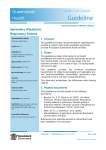
2.4.BLOCK DIAGRAM
KEY BOARD
A/D Converter
CPU
16bit
ROM 256KB
RAM 384KB
PRINTER
LCD
SERIAL COMM.
(RS-232)
Warning:
The compliance to the standards may be nullified by the following actions:
• Improper use of components not approved by the manufacturer;
• Modifications or patches not expressly authorized by the manufacturer;
• Interconnection to outside equipment not explicitly sanctioned by the manufacturer.
The manufacturer is not responsible for any accident or damage occurring as a consequence of nonobservance of this warning.
Page 8 of 66
Version 1.2
SPECIFICATIONS
Chapter 3. SPECIFICATIONS
3.1.CLASSIFICATION
1)
2)
3)
4)
5)
Type of protection against electric shock
Degree of protection against electric shock
Degree of protection against water penetration
Degree of safety of application in the presence of
flammable anaesthetic mixture with air or with
oxygen or nitrous oxide
Mode of operation
:
:
:
Class I equipment
Type B applied part
Ordinary equipment
:
:
Not suitable equipment
Continuous operation
3.2.MEASUREMENT SPECIFICATION
1)
Measurement Method
Flow detection
Volume detection
: Pneumotach Flow Sensor
: Flow Integration
Measurement range
Flow range
Volume range
: 0 to ± 14 liters/second (l/s)
: 0 to 8 liters (l)
Measurement accuracy
Flow
Volume
: ±5% indication or 0.2 l/s whichever is greater
: ±3% indication or 50 ml whichever is greater
Measurements duration and times
Vital Capacity
Forced Vital Capacity
Max. Voluntary Ventilation
: three (3) sets of 50-sec test
: three (3) sets of 25-sec test
: two (2) sets of 12-sec test
5)
Display (LCD)
: 15 characters x 8 lines (text), 120 x 64 pixels (graphics)
6)
Printer
: 32 characters/line, 46 characters/second, 58mm/width
7)
Data memory
: 50 pre-test data or 25 pre/post test data
8)
Output (RS-232C)
: 1 channel for data transmission
(This instrument may only be connected to PC
2)
3)
4)
devices
meeting EN60950 Standard)
Page 9 of 66
Version 1.2
SPECIFICATIONS
3.3.OTHER SPECIFICATION
1)
2)
3)
4)
Power supply
Voltage
Frequency
Power input
Fuse
:
:
:
:
Operating conditions
Temperature
Humidity
: 10 to 40°C
: Under 80% (no condensation)
Transport/Stocking conditions
Temperature
Humidity
: -25 to 70°C
: Under 95% (no condensation)
Dimensions
Size
Weight
100-240 V ~
50/60Hz
25 VA (max)
T 2Ax2 250V (IEC 127-2-III)
: (W) 220mm × (D) 230mm × (H) 86mm
: 1,300g (Main Unit)
500g (Flow Sensor)
5)
Casing material
: ABS (Formaldehyde free)
6)
PC connection (via RS 232C)
: This instrument may only be connected to PC devices
meeting EN60950 Standard
Page 10 of 66
Version 1.2
PARTS IDENTIFICATION
Chapter 4. PARTS IDENTIFICATION
4.1.MAIN UNIT
Number
Description
1
Power Switch
2
AC Inlet
3
Fuse Holder
4
Potential Equalization Terminal
5
Serial Communication (RS-232) Port
6
Liquid Crystal Display
7
Operational Keys
8
Printer Cover
9
Paper Outlet
10
Flow Sensor Holder
11
Heater Plug (female)
12
Sensor Tube Couplers (male)
Page 11 of 66
Version 1.2
PARTS IDENTIFICATION
4.2.INTERNAL STRUCTURE
Number
Description
13
Keyboard Assembly
14
Switching Power Supply
15
Pressure Transducer
16
Main Board
17
ROM (Read Only Memory)
18
Printer
Page 12 of 66
Version 1.2
PARTS IDENTIFICATION
4.3.FLOW SENSOR
Number
Description
19
Complete Sensor Tube
20
Tube Couplers (female)
21
Heater Plug (Male)
22
Flowhead
23
Laminar Flow Tube
4.4.ACCESSORIES
Number
Description
24
Printer Paper (Thermal-type)
25
Nose Clip
26
Tapered Rubber Tube
NOTE: Disposable paper mouthpieces are not included as a standard accessory to this instrument.
Page 13 of 66
Version 1.2
PARTS IDENTIFICATION
4.5.OPERATIONAL KEYS
Key
Description
[0] ~ [9]
Type-in keys for detail information entry
[ENT]
Delimiter for key entry confirmation
[CLR]
Cancellation of key entry detail
[ID]
Patient information entry
[VC]
Launch VC measurement and display
[FVC]
Launch FVC measurement and display
[MVV]
Launch MVV measurement and display
[POST]
Initiation of post bronchodilator test mode
[START]
Action key to begin function
[STOP]
Action key to halt terminate function
[UTILITY]
Launch support function routines
[PRINT]
Print measurement results
[FEED]
Advance / feed the printer paper
[ ▲ ], [ ▼ ]
Scroll display screen
Page 14 of 66
Version 1.2
CAUTIONS
Chapter 5. CAUTIONS
5.1.GENERAL CARE
1)
2)
3)
4)
Read and understand the instruction manual before operating the instrument.
Handle the instrument with care especially during transport.
Do not alter or repair this instrument by yourself.
No user-serviceable parts are included in this instrument. Repairs must be done by
authorized FUKUDA SANGYO service personnel only.
5.2.INSTALLATION
1)
2)
3)
4)
5)
6)
Locate the instrument atop a sturdy and level surface with a minimum 10cm clearing at both
sides and rear.
Locate the instrument in a stable environment where no abrupt temperature, humidity or
pressure change occurs.
Locate the instrument in clean surroundings where no ambient dusts, salts or ions are found.
Do not operate the instrument where the ambient temperature is over 40°C or under 10°C.
Do not immerse the instrument in water.
Do not expose the instrument to direct sunlight or excessive vibration.
5.3.ELECTROMAGNETIC COMPATIBILITY
This device has been proven to comply with EN60601-1-2 for Medical Electrical Equipment (under the
Collateral Standard for Electromagnetic Compatibility – Requirement and Tests) in the Harmonized
Standards. In order to further warrant a good level of electromagnetic immunity, it is suggested that the
instrument be kept away from devices generating electromagnetic fields or interference, such as:
loudspeakers; television sets; cellular telephones; other telephonic apparatus; or any similar devices.
5.4.FUSES REPLACEMENT
To replace the power fuses, perform the following procedures:
1) Turn the power switch of the Main Unit to OFF;
2) Disconnect the instrument from the ac mains;
3) On the rear side of the Main Unit, unscrew the two fuse holders clockwise using a suitable
tool;
4) Remove both fuses from their receptacles;
Page 15 of 66
Version 1.2
CAUTIONS
5) Substitute the blown fuse with a known good fuse of an identical characteristic with that of
the replaced fuse;
6) Restore the fuses into their receptacles and screw the fuse holder clockwise using a suitable
tool;
7) Connect the instrument to the ac mains;
8) Turn the power switch to ON;
5.5.THERMAL PAPER
This instrument includes a printer device that uses thermal paper. The proper handling of new and
unused thermal paper are observe by the following actions:
1)
2)
3)
4)
5)
Keep away from direct sunlight or placed in a high temperature environment where the
paper may discolor at about 70° C;
Keep away from prolonged exposure to fluorescent lighting;
Not to be press stored alongside a PVC film;
Contamination may occur on prolonged contact with a used thermal paper;
Used thermal paper sheets should not be carelessly thrown away in the environment but
should be subjected to disposal compliance of the present normative.
5.6.PAPER MOUTHPIECE
The rubber mouthpiece of this instrument will fit any commercially available paper mouthpiece used for
this purpose. Preference however may be limited to the following conditions:
1)
2)
3)
4)
Not less than 23.6 mm in outer diameter;
Not less than 72 mm in length;
Not less than 1.6 mm paper thickness;
Steady and long-term availability.
Page 16 of 66
Version 1.2
DISPLAY
Chapter 6. DISPLAY
6.1.PARAMETER DEFINITION
Description of Parameter
Vital Capacity
Unit
l
LCD
VC
Printer
VC
Standard
√
Expiratory Reserved Volume
l
ERV
ERV
Inspiratory Reserved Volume
l
IRV
IRV
Tidal Volume
l
TV
TV
Functional Residual Capacity
l
FRC
FRC
Residual Volume
l
RV
RV
Total Lung Capacity
l
TLC
TLC
Ratio of RV divided by TLC
%
RV/TLC
RV/TLC
Forced Vital Capacity
l
FVC
FVC
√
Forced Expiratory Volume at 0.5
l
FEV.5
FEV.5
√
Forced Expiratory Volume at 1.0
l
FEV1
FEV1
√
Forced Expiratory Volume at 3.0
l
Ratio of FEV1 divided by FVC
%
(FEV1%G)
(FEV1%G)
√
Ratio of FEV1 divided by VC
%
(FEV1%T)
(FEV1%T)
√
Ratio of FEV3 divided by FVC
%
(FEV3%G)
Ratio of FEV3 divided by VC
%
(FEV3%T)
Maximal Mid-Expiratory Flow
l/s
FEV3
MMEF
MMEF
√
Expiratory Time
s
EX TIME
EX TIME
Extrapolated Volume
l
V ext
V ext
Forced Inspiratory Vital Capacity
l
FIVC
FIVC
Forced Inspiratory Volume at 0.5 sec
l
FIV.5
Forced Inspiratory Volume at 1.0 sec
l
FIV1
Ratio of FIV1 divided by FVC
%
FIV1/FVC
Ratio of FIV1 divided by FIVC
%
FIV1/FIVC
Peak Expiratory Flow
l/s
PEF
PEF
√
Mid (Forced)-Expiratory Flow at 75%(25%)
l/s
MEF75 (FEF25)
MEF75% (FEF25%)
√
Mid (Forced)-Expiratory Flow at 50%(50%)
l/s
MEF50 (FEF50)
MEF50% (FEF50%)
√
Mid (Forced)-Expiratory Flow at 25%(75%)
l/s
MEF25 (FEF75)
MEF25% (FEF75%)
√
Peak Inspiratory Flow
l/s
PIF
PIF
√
Inspiratory flow at 50%
l/s
Maximum Voluntary Ventilation
Respiration Rate
Tidal Volume
l/min
√
MIF50% (FIF50%)
MVV
MVV
Resp/min
RR
RR
l
TV
TV
√
Parameters bracketed by () can be switched according to the utility setting.
Parameters marked by √ are printed on the standard print format.
Page 17 of 66
Version 1.2
DISPLAY
6.2.LCD SCREEN
1)
ID screen
DATE
TEMP
ID.#
AGE
Ht
Wt
SEX
RACE
2)
Jun/12/95
22 ℃
1234567890
30 yrs
171 cm
56 kg
MALE
WHITE
Auto calendar
Temperature (0 to 50°C)
ID number (maximum 10 digits)
Age (1 to 99 years)
Height (90 to 220cm)
Weight (10 to 220Kg)
Sex (MALE or FEMALE)
Race (WHITE, BLACK or OTHERS)
Comparison data screen
Measurement
VC DATA
3)
No
~
{
_
1
2
3
Pr
4.84
VC
4.70
4.66
4.62
Measurement number and Data
~ : Best data
{ : Second data
_
:Last measurement data
Predicted value
Selected data screen
FVC DATA [1]
FVC
FEV.5
FEV1
FEV1%
MMEF
TIME
4)
Measurement number
MEAS
4.58
3.16
3.84
87.4
4.66
7.69
%PR
97
Data and Predicted value
96
99
99
Selected data screen (Pre-Post)
[1]
V ext
FIVC
PEF
MEF75
MEF50
MEF25
PIF
MEAS
0.12
4.39
9.85
9.69
5.85
2.17
9.05
%CH
-1
9
12
8
6
2
2
Measurement number
Data and percentage improvement
Page 18 of 66
Version 1.2
DISPLAY
6.3.OTHER ABBREVIATION USED
Abbreviation
Meaning
%BL
Percentage (Measured Value divided by the Baseline Value)
%PR
Percentage (Measured Value divided by Predicted Value)
BSA
Body Surface Area
ENT
Enter key
Exp
Expiration
Fact
Factor
Ht
Height
ID
Identification (or Identification number)
ins
Inches
INTER
Interpretation
Insp
Inspiration
LANG
Language
lbs
Pounds
MEAS
Measured Value
p
Post Bronchodilator
PARA
Parameter
PRED
Predicted Value
Post
Post Bronchodilator
SENS
Sensor
TEMP
Temperature
TX
Transmission of data
WTX
Transmission of data with waveform
Wt
Weight
Yrs
Years
Page 19 of 66
Version 1.2
SETTINGS
Chapter 7. SETTINGS
7.1.CONFIGURATION
Prediction equations, and interpretation algorithms are user-selectable and set as follows.
Item
Predicted Equation
Description
ITS
Knudson
Morris-Polgar
ECCS
Spain
Oslo (Norway)
Chilena
Austrian
Japan
Interpretation Algorithm
ITS
NIOSH/OSHA
Ellis
Diagnosis
Unit of Height and Weight
cm/kg
ins/lbs
Unit of Temperature
°C
°F
Expression of Expiratory Flow
MEFx
FEFx
Language
English
German
French
Spanish
Flow Sensor
Fleish
Disposable
Display and print formats are executed according to the above settings. Most recent settings are
backed up by battery and kept in the memory until the next setting change. Setting operation is
described in 8.16. OTHER OPERATIONS.
ITS prediction equation will be automatically selected by the instrument in cases where ITS or ITS
(NIOSH/OSHA) interpretation is selected. No other prediction equation may be selected with the ITS or
ITS (NIOSH/OSHA) interpretation setting.
Page 20 of 66
Version 1.2
OPERATION
Chapter 8. OPERATION
8.1.PREPARATION
1) Insure the correct connection of the flow sensor to the main unit. The WHITE and the BLACK
tubes of the flow sensor secured to their matching color-coded couplers in the main unit; and,
the heater plug snugly connected to the heater jack. (Should the flow sensor tubes connection to
the main unit be reversed, inspiration and expiration flow data will be detected and shown in
the opposite polarity.
In case a disposable flow sensor is used, connect the flow sensor to the sensor handle insuring
correct direction. An engraved wart on the side of the handle shows where the patient's mouth
should be directed. We recommend using a paper mouthpiece.
2) Slide the tapered rubber tube (wide opening) to the flow sensor front-end where the rim is
marked ▲. Then, insert the cylindrical paper mouthpiece inside the tapered rubber tube
(smaller opening) about 2cm deep.
A clean mouthpiece should be provided for each patient for proper infection control.
3) After the instrument has warmed up, the flow sensor’s temperature is kept stable at
approximately 37°C. Hand-check the flowhead temperature before passing the flow sensor to
the patient.
4) It is extremely important to explain (if possible, to demonstrate) the correct measurement
maneuver the patient has to undergo in order to obtain the best test result.
5) Any time a VC, FVC or MVV test routine is initiated, the instrument performs zero-level
referencing at a NO FLOW CONDITION. For a few moments during this time, DO NOT
breathe into or move the flow sensor to prevent the instrument from erroneously capturing
zero reference at an offset. Drifting of the waveform is generally caused by this improper
action.
8.2.POWERING ON
The power switch of the instrument is located at the right side of the main unit. Toggle the power
switch towards the front marked |. Upon powering of the main unit, the instrument boots up
following the execution of a self-test routine. After a successful boot-up, an ID screen is displayed
on the LCD. If an error is detected however during self-test, the device halts and the error is
displayed on the LCD.
Use the instrument only after a thirty minutes warm-up time had elapsed for full
electronic stabilization.
Page 21 of 66
Version 1.2
OPERATION
8.3.LOADING THERMAL PAPER
To load a roll of thermal paper, jointly press and slide rearward at the area marked “PUSH ∆
OPEN” of the printer cover. The cover may then be lifted and swung open towards the back.
Take the end of the paper roll (curled-up) and insert its end into the slit located at the bottom of
the paper basin. Depress the FEED key several times until the paper advances out from the top
opening. Grab the paper end and thread it through the paper cutter outlet of the printer cover.
To secure the paper roll in the basin, close the printer cover, then jointly press and slide forward
at the area marked (embossed) “PUSH ∆ OPEN” of the printer cover to lock. Check that the
printer paper has its print face in front when the printer cover is closed. Refer to the following
picture.
8.4.ENTRY OF PATIENT'S INFORMATION
With the patient information gathered and the ID
screen displayed on the LCD, depress ID key to enter
the patient information.
The TEMP window pops on the display ready to
accept a keyed-in entry. Depress ENT key upon
completion of keyed-in entry.
DATE Jun/28/95
TEMP
22 °C
ID.#
111
AGE
yrs
Ht
TEMP
The ID screen always retains and displays the last measurement data made. Only upon complete
entry of the new patient information will the last measurement data be deleted. Should the
previous data be needed, save the data before entering the next patient ID number.
Depress the ENT key each time a complete key- entry has been made.
Page 22 of 66
Version 1.2
OPERATION
1) Date of measurement
Date is automatically provided by the built-in calendar IC.
2) Room temperature
Accepted range is from 0 - 50°C (32 to 122°F) for room temperature. The keyed-in
temperature value will automatically be the basis for BTPS correction. If a previous patient
was tested, the last temperature data is displayed.
3) ID number
Accepted range is from 0 to 9999999999 (maximum of 10 digits). The last ID number is
incremented by one should a patient data still remains in memory.
4) Age
Accepted range is from 1 to 99 years old.
5) Height
Accepted range is from 90 to 220cms (37 to 89ins).
6) Weight
Accepted range is from 10 to 220kgs (23 to 488lbs).
7) Sex
Depress the ▲ or ▼ keys to move the cursor to either the MALE or FEMALE selection.
8) Race
Press the ▲ or ▼ keys to move the cursor to either the WHITE, BLACK or OTHERS selection.
8.5.CORRECTION OF PATIENT INFORMATION ENTRY
To make a correction on the patient information ID entry, proceed in the following procedure:
1) If the erroneous entry is still in a pop-up window (where the ENT key has not yet been
depressed), depress the CLR key to delete the error in the window. You may then enter the
correct value and depress the ENT key to confirm the correction.
2) If the erroneous entry is already displayed in the ID screen (after an ENT key has been
depressed), depress the ENT key repeatedly until you have cycled through the ID menu then to
the pop-up window you wish to correct. Depress the CLR key and enter the correct value.
Then depress the ENT key repeatedly until you reach the end of the ID screen.
Page 23 of 66
Version 1.2
OPERATION
8.6.CANCELLING OF PATIENT'S INFORMATION ENTRY
This cancellation method of currently entered patient information is only possible when done
before the RACE entry information is entered. To cancel the patient information being entered,
depress any of the VC, FVC or MVV keys. The patient information is wholly canceled and the last
patient data is displayed instead.
8.7.VC MEASUREMENT
1) Depress the VC key to display the VC comparison
screen.
2) Do not breathe into or move the flow sensor while
the instrument sets zero-level referencing at a NO
FLOW CONDITION.
3) With a nose clip applied at the patient’s nostril,
make the patient breath in and out in a normal
rhythmic manner into the flow sensor mouthpiece.
Depress the START key while urging the patient to
continue normal breathing. Respiratory waveform
should now be seen in the screen.
VC DATA
No
1
2
3
VC
Pr
4.97
8l
VC [1]
50s
4) The instrument then beeps after detecting three (3)
normal cyclical breaths. Immediately make the
patient breathe in to the fullest; then breathe out
completely without force; and, thereupon return to
normal breathing. Depress the STOP key to end the
test.
8l
VC [1]
50s
5) If the measurement is not satisfactory due to respiratory disorder or an improper maneuver,
depress the START key to re-start the measurement from time zero and repeat from procedure
2). To abort measurement, depress the CLR key.
6) Duration for VC measurement is fifty (50) seconds. Depress the STOP key anytime you wish to
terminate before the time limit.
Page 24 of 66
Version 1.2
OPERATION
7) After measurement, the data comparison screen is
displayed. The best data is automatically selected
and marked ~. If multiple measurements are
performed, the second best data is marked { while
the least well data is marked _.
8) To repeat the VC measurement, repeat from
procedure 1).
VC DATA
No
~1
2
3
Pr
VC
4.90
4.97
9) Three (3) measurement data may be fully stored in memory sequenced as 1 → 2 → 3.
Subsequent measurement will overwrite the measurement data that is not marked with ~ or
{.
8.8.FVC MEASUREMENT
1) Depress the FVC key to display the FVC comparison
screen.
2) Do not breathe into or move the flow sensor while
the instrument sets its zero-level referencing at a NO
FLOW CONDITION.
3) With a nose clip applied at the patient’s nostril, make
the patient breath in and out in a normal rhythmic
manner into the flow sensor mouthpiece. Depress
the START key while urging the patient to continue
normal breathing. Respiratory waveform should
now be seen in the screen.
4) After a normal cyclical breath, immediately make
the patient breathe in to the fullest and then breathe
out completely with force. Direct the patient to
continually breathe out all the air past five seconds.
Thereupon, to breathe in again to the fullest at full
force (for Forced Inspiratory Vital Capacity
measurement); and, then return to normal
breathing. Depress the STOP key to end the test.
FVC DATA
No
1
2
3
FVC
FEV1
Pr
4.97
4.16
12
l/s
F-V [1]
0
8l
12
l/s
F-V [1]
0
8l
Page 25 of 66
Version 1.2
OPERATION
5) If the measurement is not satisfactory due to respiratory disorder or improper maneuver,
depress the START key to re-start the measurement from zero-time and repeat from procedure
2). To abort measurement, depress the CLR key.
6) Duration for FVC measurement is twenty-five (25) seconds. Should you wish to terminate
before the time limit, press STOP key.
7) After measurement, the data comparison screen is
displayed. The best data is automatically selected
and marked ~. If multiple measurements were
performed, the second best data is marked { while
the least well data is marked _.
FVC DATA
No
~1
2
3
FVC
4.85
FEV1
4.26
Pr
4.97
4.16
8) To repeat the FVC measurement, repeat from procedure 1).
9) Three (3) measurement data may be fully stored in memory sequenced as 1 → 2 → 3.
Subsequent measurement will overwrite the measurement data that is not marked ~ or {.
8.9.MVV MEASUREMENT
1) Depress the MVV key to display the MVV
comparison screen.
2) Do not breathe into or move the flow sensor while
the instrument sets its zero-level referencing at a
NO FLOW CONDITION.
3) With a nose clip applied at the patient’s nostril,
make the patient breath in and out in deep and
rapid rhythmic manner into the flow sensor
mouthpiece. Depress the START key while urging
the patient to keep the voluntary effort on a
constant rhythm like one-two, one-two. Respiratory
waveform should now be seen in the screen
MVV DATA
No
1
2
MVV
Pr
169.9
4l
MVV [1]
12s
Page 26 of 66
Version 1.2
OPERATION
4) If the measurement is not satisfactory due to respiratory disorder or improper maneuver,
depress the START key to re-start the measurement from zero-time and repeat from procedure
2). To abort measurement, depress the CLR key.
5) Duration for MVV measurement is 12 seconds, the generally recommended test duration. To
abort measurement, depress the STOP key. The instrument however requires a measurement
of more than five seconds for analysis.
6) After measurement, the data comparison screen is
displayed. The best data is automatically selected
and marked { while the least well data is marked
_.
MVV DATA
No
~1
2
MVV
182.4
Pr
169.9
7) To repeat the MVV measurement, repeat from procedure 1).
8) Two (2) measurement data may be fully stored in memory sequenced as 1 → 2. Subsequent
measurement will overwrite the measurement data that is not marked {.
8.10.POST-BRONCHODILATOR TESTING
This instrument is capable of performing post-bronchodilator testing for each measurement.
1) For single patient testing:
a) Perform on the patient the VC, FVC, or MVV tests desired and select the best data from
the measurements made. The selected measurement shall serve as the pre-bronchodilator
data of the patient. If so required, the appropriate procedure for report printing or data
transfer should be done now.
b) Proceed in the administering of the medication to the patient. The post-bronchodilator
test is typically conducted after a fifteen-minute period.
c)
Depress the POST key to set the patient pre-bronchodilator data into memory afterwhich
the patient ID screen is displayed. The post-bronchodilator test is now ready.
Page 27 of 66
Version 1.2
OPERATION
d) Perform the post-bronchodilator test using the same VC, FVC, or MVV test procedure
desired. The pre-bronchodilator and post-bronchodilator measurement data, as well as
the response rate are thereupon displayed. [Post] is indicated on the comparison data
screen.
e) Enter a new patient ID to exit Post Bronchodilator Testing.
2) For multiple patients testing:
a) Perform on the individual patient the VC, FVC, or MVV tests desired and select the best
data from the measurements made. The selected measurement shall serve as the prebronchodilator data for each individual patient. If so required, the appropriate procedure
for report printing or data transfer should be done now. Therewith, save the
measurement data into memory using the procedures outlined in 8.17. OTHER
FUNCTIONS.
b) Proceed in the administering of the medication to the patient.
c)
Perform procedures 2.a) through 2.b) in acquiring measurements, data saving and
administration of medication to the other patients in repeated order.
d) To move on to post-bronchodilator testing, read out from memory the concerned patient
measurement data using the procedures outlined in 8.17. OTHER FUNCTIONS. Depress
the POST key to set the patient pre-bronchodilator data into memory afterwhich the
patient ID screen is displayed. The post-bronchodilator test is now ready for the
concerned patient.
e) Perform post-bronchodilator test on the concerned patient using the same VC, FVC, or
MVV test procedure desired. The pre-bronchodilator and post-bronchodilator
measurement data, as well as the response rate are thereupon displayed. [Post] is
indicated on the comparison data screen.
3) In saving the pre-and the post measurement data into the memory, there will be two data sets
consisting of pre data and post data for the same patient. If the pre data is not necessary,
delete the pre data.
4) Repeat the same procedure of 2.d) through 2.f) to the other patients.
5) Enter a new patient ID to exit Post Bronchodilator Testing.
Page 28 of 66
Version 1.2
OPERATION
8.11.BRONCHIAL CHALLENGE TESTING
This instrument is capable of performing Bronchial Challenge test.
Warning:
Prior to subjecting a patient to Bronchial Challenge Test, check the condition of the patient,
the kind and dosage interval of the medicine allowable for the patient. Always have the
bronchodilator ready during the test.
1)
Flow of measurement
Measurement and registration of base line data
Setting of baseline date (BASE)
Saline Inhalation measurement and registration (Control)
Dose Inhalation, concentration values entry, measurement and registration (DOSE)
repeating up to certain concentration as may be required
Bronchodilator Inhalation, concentration value entry, measurement and registration
(RECOVERY)
Printout of measurement result
2)
a)
Measurement and setting-up of the patient baseline data
Measurement
Perform FVC measurement on the patient to obtain a baseline data (commonly the best data
realized from the test). VC and MVV tests may still be conducted, however measurement
results will not be printed on the Bronchial Challenge test report. If required, the appropriate
procedures for report printing or data transfer should be done now. Catalogue the patient
Page 29 of 66
Version 1.2
OPERATION
measurement data into memory by using the memory save procedure in 8.16. OTHER
FUNCTIONS.
b)
3)
Setting up of the baseline data
To start baseline data set-up, depress the UTILITY key and select item 5:BASE. Select by
using the numeral keys with the patient ID number earlier catalogued in procedure 2.a) from
the list of displayed ID numbers. Depress the ENT key to now set the patient baseline data
and upon display of the ID menu, the instrument is now prepared for Bronchial Challenge
testing. This test mode is kept until a new patient ID is selected.
Measurement with Saline Inhalation
a)
Omit this procedure and proceed to procedure 4) if the Saline measurement is not required.
b)
Make the patient inhale Saline with a nebulizer as per prescribed dose.
c)
Perform an FVC measurement similar to procedure 2.a) to obtain a Saline control data. If
Saline Inhalation performance data is required, catalogue the patient measurement data into
memory by using the memory save procedure in 8.17. OTHER FUNCTIONS.
4)
Measurement with Dose Inhalation
a)
Make the patient inhale Methacholine or the like with a nebulizer as per prescribed dose.
Note the administered dose in milligrams.
b)
Depress the UTILITY key and select item 5:DOSE from the utility menu. Enter the
administered dose noted from procedure 4.a) into the dose concentration screen using the
numeral keys. Depress the ENT key to confirm entry or use the CLR key to re-enter. The new
concentration value is hence updated and the ID screen is displayed ready for re-test. A “NO
DATA” message is momentarily displayed on screen if the Saline Inhalation Measurement
was omitted.
c)
The concentration entry is validated for values between the range:
0.01 to 999.98mg: DOSE MEASUREMENT
d)
The concentration value entered should always be higher than the currently registered value.
For instance, if the current value was 0.08, the next acceptable value should be 0.09.
e)
Perform an FVC test; then select; and, store the best data into the memory. For each
concentration value where Dose Inhalation performance data is required, catalogue the
patient measurement data into memory by using the memory save procedure in 8.17. OTHER
FUNCTIONS.
Page 30 of 66
Version 1.2
OPERATION
f)
Increase the dose as prescribed and repeat the above measurement of procedure 4.a) through
4.e).
g)
When the present FEV1 value should decrease less than 80% of the base line FEV1 data, the
following message is displayed.
FEV1 %BL = ××% (××<80%)
h)
Depress the ENT key to display the data screen. Use the ▼ or ▲ keys to scroll through the
measured values.
In any event that the FEV1 decreases abruptly, discontinue further dose
and proceed to Bronchodilator Inhalation.
5)
Measurement with Bronchodilator Inhalation
a)
Omit this procedure if the Bronchodilator Inhalation is not required. However, administer
Bronchodilator Inhalation to the patient for recovery.
b)
Make the patient inhale Bronchodilator using a nebulizer as per required dose.
c)
Depress the UTILITY key and select 5:DOSE. Dose concentration screen is displayed and the
last concentration value is displayed. Enter the concentration value 99999 and depress the
ENT key.
999.99mg:BRONCHODILATOR MEASUREMENT
d)
When the ID screen is displayed, perform FVC measurement then select and store the best
data into the memory. If Bronchodilator Inhalation performance data is required, catalogue
the patient measurement data into memory by using the memory save procedure in 8.17.
OTHER FUNCTIONS.
e)
To redo the Bronchodilator measurement, repeat the above measurement procedures 5.a)
through 5.d).
6)
a)
Bronchial Challenge print data
Only previously catalogued measurement data during Bronchial Challenge testing mode may
be printed. The printout shall consist of: base line measurement data; each measurement data
for Saline Inhalation and Dose Inhalation; catalogued concentration value; ratio of
performance against the baseline data; time duration from measurement of baseline data;
and, graphed FEV1 changes. To enable the foregoing printout, depress the PRINT key or use
the printing function of 8.17. OTHER FUNCTIONS.
Page 31 of 66
Version 1.2
OPERATION
7)
Cancellation of Bronchial Challenge Mode
a)
Cancellation of Bronchial Challenge test mode may be done through either of the following:
i) Entering of a new patient ID using the ID key function. After the entry of the full patient
information, the Bronchial Challenge Mode is automatically canceled.
ii)
Reloading of a patient data using the memory load function of 8.17. OTHER FUNCTIONS.
8.12.DATA PROTECTION FROM OPERATIONAL ERROR
Recovery from operational errors may be circumvented by the following:
1) Inadvertent depressing of the ID key
Whenever the ID key is depressed, the ID screen readies for the next patient entry. Depress the
VC, FVC or MVV key to return display of the last patient data. However, if the new patient
data have been entered up to the RACE window and the ENT key is depressed, the last patient
data will already be deleted.
2) Inadvertent depressing of the START key
Whenever the START key is depressed, the measurement screen is displayed. To recover,
depress the CLR key to cancel the measurement and have the data comparison screen restored
in the display.
8.13.SELECTION AND DISPLAY OF DATA
This instrument stores three (3) VC, three (3) FVC and two (2) MVV data sets per patient in the
memory. Each data can be selected and displayed. The best and second best data are automatically
selected on each measurement under the following conditions.
Measurement
Criteria
Best VC data
The largest VC value
Best FVC data
The largest value of FVC + FEV1
Best MVV data
The largest MVV value
Data selection can be manually selected with the numerical keys 1, 2, or 3. The selected data will be
marked ~. In the event, a measurement is conducted more than three time (3X) for both the VC and
FVC tests and two times (2X) for the MVV, the data without the marks ~ or { is overwritten in the
display and marked with _ by the new measurement.
Page 32 of 66
Version 1.2
OPERATION
8.14.EXPANDED WAVEFORM SCALE
Where an expanded graphical scale is required, depress the ENT key to shift the graphical display to
double scale (2X) during measurement or display. Selecting double scale on the display will also
cause the waveform to be printed as such. To return to normal scale, depress the ENT key to toggle
back.
8.15.RECORD FILING IN MEMORY
Patient data and measurement records are filed in memory using the memory save function under
8.17. OTHER FUNCTIONS.
1)
2)
3)
a)
b)
c)
d)
Recorded data, consisting of a patient and
measurement data, is automatically catalogued by a
unique tag number and classified according to
usage as shown where each row consists of a record
entry. The three columns showing the unique tag
number, record type, and associated patient ID
number respectively. To view all records in storage,
use the ▼ or ▲ keys to scroll over.
1:
1
2:
0002
3:
0000000003
4: P 0000000004
5:
5
6: B
0000006
7: D
0000006
SELECT # : _
Data records are chronologically stored and are classified in the following types:
Record
Type
Record space
used
P
B
D
1
2
1
1
Description
Pre Data Record
Pre/Post Data Record
Baseline Data Record
Dose Data Record
Where:
Pre data record is created when saving the typical patient VC, FVC, MVV measurement data;
Pre/Post data record is created when saving a Post Bronchodilator measurement result;
Baseline data record is a reclassified Pre data record that was utilized as baseline data for
Bronchial Challenge Testing; and,
Dose data record is created whenever a dose test measurement result is saved.
Page 33 of 66
Version 1.2
OPERATION
The maximum memory capacity of the instrument is as follows:
Record Type
Maximum Memory Capacity
Only Pre Data Record
50 data sets
Pre/Post Data Record
25 data sets
A Pre/Post data Record, although assigned one tag number, actually uses two record spaces
when saved.
8.16.PRINTING OF DATA
Depress the PRINT key to print the current measurement result. All the selected measurement data
are printed on two print formats, which can be user-selected as standard or detail. The procedure for
selecting the print format can be referred to 8.17. OTHER FUNCTIONS. To cancel printing, depress
the PRINT key.
8.17.OTHER FUNCTIONS
Depress the UTILITY key to display the menu screen.
Select the desired function by keying the item number and
depressing the ENT key to initiate operation.
Depress the STOP key to return to the ID screen.
Use the ▼ or ▲ keys to scroll through the screens.
1:
2:
3:
4:
5:
6:
7:
8:
MEMORY
CALIBRATION
TRANSMISSION
FRC
BASE
PRINT
DATE
MODE
9: CONTRAST
Page 34 of 66
Version 1.2
OPERATION
1)
Memory File Function (MEMORY)
Select option 1: MEMORY from the UTILITY menu
by keying the numerical label (1) and the ENT key
to do memory filing functions (saving, loading,
deleting and printing of data).
[MEMORY]
1:
2:
3:
4:
SAVE
LOAD
DELETE
PRINT
Depress the STOP key to cancel and return to the ID screen.
a)
Saving of Measurement Data (SAVE)
Store or catalogue the current patient ID and
ID. # 1234567890
measurement data into memory. Select option 1:
OK
TOTAL
: 5
SAVE from the MEMORY menu to initiate.
REST
PRE
:
45
Operation saves one data at a time. Successful
REST POST
: 22
data save operation is confirmed with the ID#
confirmation screen displayed. Where the
TYPE ENT KEY
confirmation screen shows:
(ID. #)
- the ID number of the current
measurement data saved;
(TOTAL)
- the total number of data saved in the memory including the current data;
(REST PRE) - the remaining memory capacity if only pre (regular) data are saved;
(REST POST) - the remaining memory capacity if pre and post data are saved.
b)
Reloading of Saved Measurement Data (LOAD)
1:
1
Reload a selected patient measurement data for
2:
0002
further operation. Select option 2: LOAD from the
3:
0000000003
MEMORY menu to display the ID numbers of
4: P 0000000004
data stored in the memory. Select the patient ID
5:
5
6: B
0000006
number and key in the prefixed item number and
7: D
0000006
depress the ENT key. If there are seven data sets
SELECT # : _
stored, depress ▲ or ▼ arrow keys to scroll through
the list of ID numbers stored in the memory.
Depress the STOP key to cancel and return to the ID screen.
c)
Deletion of Measurement Data (DELETE)
Deletes measurement data stored in the memory.
Select option 3: DELETE from the MEMORY
menu to initiate. Select from two deletion options
namely: selective deletion; or, total deletion.
Selective deletes a specific data per operation.
While, total deletes all data stored in the memory.
[DELETE]
1: SELECT
2: ALL
Page 35 of 66
Version 1.2
OPERATION
i)
ii)
1: SELECT
Select option 1: SELECT from the DELETE
menu to display the ID numbers of data stored
in the memory. Select the patient ID number
and key in the numerical tag number and
depress the ENT key. Depress the ▲ or ▼ arrow
keys to scroll through the list of ID numbers in
the memory.
When the patient data to be deleted is selected,
a confirmation screen is displayed. Depress 1
key and then ENT key to confirm deletion or
depress 0 key and then the ENT key to cancel
deletion. Thereafter, the screen returns to the
ID screen.
1:
1
2:
0002
3:
0000000003
4: P 0000000004
5:
5
6: B
0000006
7: D
0000006
SELECT # : _
[SELECT]
ID. # 0000000001
YES
NO
: [1]
: [0]
SELECT # : _
iii)
d)
2)
2:ALL
Select option 2: ALL from the DELETE menu to
initiate total deletion. Confirm action by
depressing 1 and then the ENT key to effect
total deletion or depress 0 and then the ENT
key to cancel deletion action. Thereafter, the
screen returns to the ID screen.
[ALL]
YES
NO
: [1]
: [0]
SELECT # : _
Printing of Saved Measurement Data (PRINT)
Select option 4: PRINT from the MEMORY menu to enables the printing of all saved
measurement data. The printout format shall depend on the data set type; i.e., Pre data, Post
data, BASE data, or DOSE data.
Auto calibration (CALIBRATION)
Select option 2: CALIBRATION from the UTILITY menu by keying the numerical label (2) and
the ENT key to conduct calibration.
Auto calibration is done with an optional three-liter calibration syringe. Where it is
recommended that calibration constancy be checked before and after each measurement
session. Prior to calibration, remove the heater jack of the flow sensor from the main
unit.
Page 36 of 66
Version 1.2
OPERATION
a)
Connect the three-liter calibration syringe to the flow sensor in a level line. Pull back the
shaft of the calibration syringe to its end and leave as is.
b)
The zero level reference is detected at this time.
Do not move the shaft of the calibration syringe.
The calibration scale is displayed when ready.
12
l/s
0
c)
Depress the START key.
Push the shaft of the syringe smoothly to its end
to empty all three liters of air into the flow sensor.
The flow volume curve is displayed on the scale.
12
L/S
0
d)
e)
Then pull the shaft of the syringe smoothly to its
end to take in three liters of air through the flow
sensor. In auto calibration, only the upper scale is
shown on the display. The inspired and expired
flow curves are thus shown superimposed on the
scale. After a cycle, the two flow curves disappear
and the computer beeps.
8l
8L
12
l/s
0
8l
Repeat procedures 2.c) through 2.d) three times using varying speeds of emptying the
calibration syringe to include flow linearity consistency. If you wish to cancel auto
calibration, depress the STOP key. The screen returns to the ID screen.
Page 37 of 66
Version 1.2
OPERATION
f)
When the three calibration cycles are done, the
inspiratory and expiratory average values and
correction factors of the three measurements are
displayed. The correction factor is then registered
with the software.
[CALIBRATION]
Meas
Exp
3.00
Insp
3.01
Fact
1.000
0.997
Target 3.00 L
TYPE ENT KEY
g)
Depress the ENT key to terminate the auto
calibration routine.
h)
The auto calibration acceptable tolerance is ± 1 liter from 3.0 liters. Taken by averaging the
three autocalibration measurements for both expiration and inspiration cycles reckoned from
3.0 liters. If the average value is out of the acceptable tolerance, an error message
"IMCOMPLETE" will be displayed. In this case, depress the ENT key to return to ID menu
screen and check the connection of the calibration syringe and the flow sensor. Repeat the
auto calibration routine.
In the event that the auto calibration procedure consistently results in an
“INCOMPLETE NG” message, submit your equipment for check-up to your Fukuda
Sangyo dealer.
3)
a)
b)
c)
d)
e)
Data transmission (TRANSMISSION)
Select option 3: TRANSMISSION from the UTILITY menu by keying the numerical label (3)
and the ENT key to conduct data transfer operation. All the data stored in this instrument can
be transferred to a PC using optional software "FS/PC-95". Contact your dealer about the detail
specification for data transmission.
Before beginning data transmission, check the
connection of the PC and the status of data
acceptance.
Depress 1 key (1:TX) and then the ENT key to
transfer data only.
Depress 2 key (2:WTX) and then the ENT key to
transfer data and waveforms.
When either transmission is selected, data
transfer is started with following display. Where
the screen shows the total number of data stored
and the number of data sets already transferred.
If you wish to cancel data transmission, depress
the STOP key to return to the ID screen.
[TRANSMISSION]
1: TX
2: WTX
SELECT # : _
[WTX]
DATA OUTPUT
WAIT!
XX / XX
Page 38 of 66
Version 1.2
OPERATION
f)
g)
4)
a)
If any problem is encountered during data
transmission, the following error message is
displayed.
Depress the ENT key to return to the ID screen.
Fix the problem and repeat the data transmission
procedure.
Entry of FRC value (FRC)
Select option 4: FRC from the UTILITY menu by
keying the numerical label (4) and the ENT key.
FRC value, as measured by other Pulmonary
Function Testing regimen, may be entered. Where
RV value and associated parameters are computed
from the entered FRC value and the VC data.
[WTX]
Communication NG
TYPE ENT KEY
[FRC]
FRC =
0.00 L
Enter the FRC value with the numeral keys.
[FRC]
b)
On complete entry, the FRC value is interpreted as
a two decimal-place number. Key entry of the
number is on a first-in last-out sequence (where
the digit is positioned to where the underline is).
To enter an FRC value of 3.02 liters, enter the "3",
"0", "2" in sequence and depress the ENT key.
c)
If an erroneous value is entered, depress the CLR key and enter correct value.
d)
If you wish to cancel the FRC entry, depress the STOP key to return to the ID screen.
5)
FRC =
3.02 L
Setting up Bronchial Challenge Testing (BASE) / Entry of Concentration during Bronchial
Challenge Testing (DOSE)
Select option 5: BASE or DOSE from the UTILITY menu by keying the numerical label (5) and
the ENT key to do Bronchial Challenge Testing.
Prior to initiation of Bronchial Challenge Test Mode, UTILITY function 5: indicates BASE.
Only during Bronchial Challenge Testing will UTILITY function 5: indicate DOSE.
After a baseline measurement data is loaded, the instrument automatically changes into
Bronchial Challenge testing mode. Once this operation is entered, the mode is kept until
a new patient ID is entered. Printing of Bronchial Challenge performance data may be
done only after saving the data set as a DOSE set data.
Page 39 of 66
Version 1.2
OPERATION
a)
When in BASE option, the ID numbers of earlier measured and saved patient data are
displayed. Enter the patient ID number using the prefix numerical tag number and depress
the ENT key. When the ID screen is displayed, the selected data is now loaded as the baseline
data. Bronchial Challenge Testing is now ready.
b)
After administering the drug to the patient, select option 1: DOSE from the UTILITY menu by
keying the numerical label (5) and the ENT key.
c)
The DOSE initial setting as displayed for a
patient is pre-set to 0.00 while subsequent
settings displays the last entered value.
[DOSE]
DOSE
=
0.00 mg
TYPE ENT KEY
d)
Enter the concentration value administered to the patient with the numeral keys.
e)
On complete entry, the dose value is interpreted
as a two decimal-place number. Key entry of the
number is on a first-in last-out sequence where the
entered digit is positioned to where the underline
is). To enter a dose value of 1.32 mg, enter "1",
"3", "2" in sequence and depress the ENT key.
[DOSE]
DOSE
=
1.32 mg
TYPE ENT KEY
f)
If you enter the wrong value, depress the CLR key and enter the correct value. The screen
returns to the ID screen.
g)
If you wish to cancel the DOSE entry, depress the STOP key to return to the ID screen. The
last entered value is retained.
h)
The entry values acceptable are listed in the following:
Type
Description
Accepted range
Saline
Measurement with inhalation of Saline
0.00
Dose
Measurement with inhalation of Dose
0.01 to 999.98
Recovery
Measurement with inhalation of bronchodilator
999.99
Page 40 of 66
Version 1.2
OPERATION
6)
Setting of the Printout Format (PRINT)
Select option 6: PRINT from the UTILITY menu by keying the numerical label (6) and the ENT
key to alter printing format of reports.
a)
i)
Upon initiation, the current print format setting is
displayed. Depress the STOP key when no
change to the current setting is desired. Else,
depress the ENT key to display the pop up
window screen. When inside the pop-up window
screen, use the ▲ or ▼ keys to move the cursor to
the selected item requiring the change and
depress the ENT key to confirm selection.
COPY specifies the number of report copies to
be printed. User-selectable between singlecopy and multiple-copy (2 – 4 sheets) printing.
[PRINT]
COPY
FORM
PRED
INTER
:
:
:
:
1
STANDARD
OFF
ON
[PRINT]
COPY
1
2
3
4
ii)
FORM specifies the report format selection.
User-selectable between STANDARD and EXTRA.
STANDARD prints in summary report form while
EXTRA prints in detail report form
[PRINT]
COPY
FORM
: 1
: STANDARD
FORM
STANDARD
EXTRA
iii)
PRED specifies whether inclusion of the
predicted curve in the FVC print report is
desired. Standard setting is OFF. If ON is
selected, the predicted curve is printed with
the actual F-V curve on the FVC graphical
scale.
PRED
ON
OFF
PRED
INTER
: OFF
: ON
Page 41 of 66
Version 1.2
OPERATION
iv)
b)
7)
a)
b)
8)
a)
INTER specifies whether inclusion of the
interpretation summary in the print report is
desired. Standard setting is ON, where the
interpretation summary is inclusive in the
print report.
If OFF is selected, the
interpretation summary will not be printed.
INTER
ON
OFF
PRED
INTER
: OFF
: ON
When the print setting is completed, the setting screen is displayed. Check the setting.
Depress the STOP key to end the print setting. The screen returns to the ID screen. Setting is
backed up by battery until new setting is changed.
Setting of date and time (DATE)
Select option 7: DATE from the UTILITY menu by keying the numerical label (7) and the ENT
key to change date and time settings.
Upon entering, the currently set date and time are
displayed. A change may be made at the item
where the cursor is positioned. Enter the change
with the numeral keys and depress the ENT key to
move the cursor to the successive item.
[DATE]
YEAR
MONTH
DAY
HOUR
MINUTE
=
=
=
=
=
95
7
12
11
25
Depress the STOP key to end the DATE setting. The screen returns ID screen. This setting is
backed up by battery until a new setting is made.
Setting of system mode (MODE)
Select option 8: MODE from the UTILITY menu by keying the numerical label (8) and the ENT
key to select desired prediction equations, interpretation programs and measuring parameters.
Upon entering, the current mode setting is
displayed. Depress the STOP key when no
change to the current setting is desired. Else,
depress the ENT key to display the pop-up
window screen. When inside the pop-up window
screen, use the ▲ or ▼ keys to move the cursor to
the selected item requiring the change and
depress the ENT key to confirm selection.
PRED
INTE
UNIT
TEMP
FEVx
PARA
LANG
SENS
:
:
:
:
:
:
:
:
ECCS
DIAG
cm/kg
°C
FEV1%T
MEFx
ENGLISH
Fleisch
Page 42 of 66
Version 1.2
OPERATION
i)
ii)
PRED specifies the predicted equation to
apply. Where applicable sets of prediction
equations may be user-selectable. In cases
however that ITS or ITS (NIOSH/OSHA)
interpretation is selected, only ITS prediction
equation may be selected.
INTE specifies the interpretation algorithm to
use. Where four (4) kinds of interpretation
may be user-selectable.
PRED
ITS
KNUDSON
MORRIS
ECCS
SPAIN
OSLO
INTE
ITS
NIOSH/OSHA
ELLIS
DIAGNOSIS
SENSE
iii)
UNIT specifies the height and weight units
that are used during patient ID entry. Where
selection may be Metric (cm/kg) or English
(ins/lbs).
UNIT
cm/kg
ins/lbs
PARA
LANG
SENSE
iv)
TEMP specifies the temperature unit that is
used during patient ID entry. Where selection
may be Centigrade (°C) or Fahrenheit (°F).
: Fleisch
: MEFx
: ENGLISH
: Fleisch
TEMP
°C
°F
PARA
LANG
SENSE
v)
FEVx specifies which expression of
FEV1%T(FEV1/VC) & FEV3%T(FEV3/VC) or
FEV1%G(FEV1/FVC) & FEV3%G(FEV3/FVC)
during FVC measurement to use. Where
FEVx%T or FEVx%G may be selected.
: MEFx
: ENGLISH
: Fleisch
FEVx
FEVx%T
FEVx%G
PARA
LANG
SENSE
: MEFx
: ENGLISH
: Fleisch
Page 43 of 66
Version 1.2
OPERATION
vi)
PARA specifies which expression of Maximum
(Forced)
Expiratory
Flow
on
FVC
measurement to use. Where MEFx or FEFx
may be selected.
PARA
MEFx
FEFx
PARA
LANG
SENSE
vii)
LANG specifies the language to be use. Where
four (4) languages may be selected.
LANG
ENGLISH
GERMAN
FRENCH
SPANISH
PARA
: MEFx
SENSE
viii)
SENS specifies the kind of sensor to be used.
Where FLEISCH or DISPO may be selected
depending on the type of flowhead the patient
intends to use.
9)
: MEFx
: ENGLISH
: Fleisch
On completion of the mode setting, the setting
screen is displayed. Check each setting. Depress the STOP key to end the mode setting. The
screen returns to the ID screen. The current setting is backed up by battery until a new
setting is changed.
Contrast Adjustment (CONTRAST)
Select option 9: CONTRAST from the UTILITY menu by keying the numerical label (9) and the
ENT key to adjust the LCD display contrast.
a)
Upon entering, the contrast display line is shown.
b)
Depress the ▲ key to darken or the ▼ key to lighten
the display. An “*” mark will move right or left
according to the contrast adjustment.
c)
: Fleisch
SENS
Fleisch
Dispo
PARA
LANG
SENSE
b)
: MEFx
: ENGLISH
: Fleisch
[CONTRAST]
+
------------+----------*
Depress the ENT key to end the contrast
adjustment. The screen returns to the ID menu
screen.
Page 44 of 66
Version 1.2
SAFEKEEPING
Chapter 9. SAFEKEEPING
9.1.Stowing
For prolonged storage of the instrument, the following prior action should be conducted:
1) Insure that the instrument power switch is set to off. Disconnect the power cord from a wall
socket.
2) If the instrument is soiled, wipe clean using a mild detergent in a dampen cloth. Then wipe off
with a dry cloth until no detergent remains.
3) Do not immerse the instrument in water, expose to direct sunlight or subject to excessive
vibration at any time.
4) For best storage protection, store the instrument in its original packaging and seal.
5) Do not store the instrument on places where a large temperature, humidity or pressure change
occurs; or, where ambient dusts, salts or ions are found.
6) Check all the accessories and keep with the main unit.
Warning:
If the main unit or flow sensor is dropped, it is mandatory that a thorough check of the system
be performed by an authorized Fukuda Sangyo service personnel. Further use of the
instrument should only be done after a satisfactory inspection.
Page 45 of 66
Version 1.2
CLEANING AND STERILIZING
Chapter 10. CLEANING AND STERILIZING
Before using the instrument and for each patient perform the
following:
•
•
Replace the paper mouthpiece.(disposable accessory)
Sterilize the laminar flow tube and the tapered rubber tube
The laminar flow tube (metal) can be easily slipped out the flow head.
10.1.CLEANING THE EXTERNAL OF THE INSTRUMENT
•
•
•
Warning:
Always unplug the instrument before cleaning!
Do not use any scrubbing agents or solvents (alcohol, acetone) to
clean the instrument or its accessories.
Generally, any cleaning procedure that heats the materials above
45°C may affect the life of the material.
1) You may clean the external surfaces of the instrument with a damp cloth or sponge
safeguarding however that no drips flows along the surface of the instrument.
2) Insure that the instrument is completely dry following a cleaning procedure.
10.2.TAPERED RUBBER TUBE
Pull out the rubber tube from the flow sensor to free.
1) Do not use Ethylene Oxide gas to sterilize the tapered rubber tube. The gas may
cause incursion into the material where toxicity may remain.
2) Do not use alcohol or alcohol-based solutions to clean the tapered rubber tube.
These solutions may cause hardening of the material thus reduce the life of the
material.
3) The sterilization procedure for the tapered rubber tube can be done using a detergent
water solution containing a maximum volume percentage of 20% of Cidex, Citrosil, or the
like.
Push in the rubber tube into the front side of the flow sensor to ready.
10.3.LAMINAR FLOW TUBE (METAL)
To remove the laminar tube from the flowhead, hold the flowhead rigidly with its front side
towards you and grasp the laminar tube with the free hand. Rotate the laminar tube about onePage 46 of 66
Version 1.2
CLEANING AND STERILIZING
eight clockwise. Turning the flowhead on its backside, push out the laminar tube until clear of the
flowhead. Proceed to the cleaning of the bare laminar flow tube using the following methods:
1) You may use Ethylene Oxide gas to sterilize the laminar flow tube.
2) You may autoclave the laminar flow tube up to 132°C of temperature (2 bar, 10
minutes).
3) The sterilization procedure for the laminar tube can be done using a detergent water solution
containing a maximum volume percentage of 20% of Cidex, Citrosil, or the like.
Make sure that the laminar flow tube is completely dry before reusing.
Remaining water drops (even in small amounts) may cause measurement errors.
Shake the laminar flow tube to remove water drops.
To re-install the laminar tube into the flowhead, position the laminar tube to the front side of the
flowhead with the locking lug of the laminar tube located at your left and near side. Push slide the
laminar tube until the locking lug firmly sets into the flowhead slit. With the flowhead rigidly with
its front side towards you, grasp the laminar tube with the free hand and rotate one-eight clockwise
to lock.
10.4.NOSECLIP CLEANING
The nose clip must be cleaned before each patient use with alcohol or a detergent
solution.
Page 47 of 66
Version 1.2
PREDICTED EQUATIONS
Chapter 11. PREDICTED EQUATIONS
11.1.ITS (Intermountain Thoracic Society)
Parameter
Sex
VC (l)
FVC (l)
FEV.5 (l)
FEV1 (l)
M
FEV1%G (%)
FEV3%G (%)
MMEF (l/s)
PEF (l/s)
7-18 W
Predicted Equation
95% CI
Reference
Pred VC = Pred FVC
3.58×10⁻⁴×H3.18÷1000
-3
M
7-18 B
1.07×10 ×H2.93÷1000
M
19+
0.0600×H−0.0214×A−4.650
-3
13
1 (Hsu)
17
1 (Hsu)
1.12
1 (Crapo)
F
7-18 W
2.57×10 ×
F
7-18 B
8.34×
F
19+
0.0491×H−0.0216×A−3.590
0.68
1 (Crapo)
M
19+
0.0327×H−0.0152×A−1.914
0.71
1 (Crapo)
F
19+
0.0238×H−0.0185×A−0.809
0.51
1 (Crapo)
M
7-18 W
7.74×10⁻⁴×H3.00÷1000
×
10-4
÷1000
14
1 (Hsu)
÷1000
15
1 (Hsu)
H2.78
H2.98
-3
M
7-18 B
1.03×10 ×H2.92÷1000
M
19+
0.0414×H−0.0244×A−2.190
7-18 W
3.79×10⁻³×H2.68
F
FEV3 (l)
Age
( all )
÷1000
÷1000
13
1 (Hsu)
17
1 (Hsu)
0.84
14
1 (Crapo)
1 (Hsu)
F
7-18 B
1.14×10⁻³×H2.89
F
19+
0.0342×H−0.0255×A−1.578
0.56
1 (Crapo)
M
19+
0.0535×H−0.0271×A−3.512
1.02
1 (Crapo)
F
19+
0.0442×H−0.0257×A−2.745
0.62
1 (Crapo)
M
19+
−0.1300×H−0.152×A+110.49
8.3
1 (Crapo)
F
19+
−0.2020×H−0.252×A+126.58
9.1
1 (Crapo)
M
19+
−0.0627×H−0.145×A+112.09
4.6
1 (Crapo)
F
19+
−0.0937×H−0.163×A+118.16
5.4
1 (Crapo)
7-18 W
7.98×10⁻⁴×H2.46
26
1 (Hsu)
M
÷60
÷60
15
1 (Hsu)
M
7-18 B
3.61×10⁻⁴×H2.60
M
19+
0.0204×H−0.0380×A+2.133
F
7-18 W
3.79X10⁻³×H2.16÷60
28
1 (Hsu)
F
7-18 B
1.45X10⁻³×H2.34÷60
30
1 (Hsu)
F
19+
0.0154×H−0.0460×A+2.683
7-18 W
3.35×10⁻⁴×H2.79
M
36
1.67
1.36
÷60
18
÷60
22
1 (Hsu)
1 (Crapo)
1 (Crapo)
1 (Hsu)
M
7-18 B
1.74×10⁻⁴×H2.92
M
19-24
0.078×H+0.166×A−8.060
K1
M
25+
0.094×H−0.035×A−5.993
K1
F
7-18 W
2.58×10⁻³×H2.37÷60
18
1 (Hsu)
F
7-18 B
5.51×10⁻⁴×H2.68
÷60
20
1 (Hsu)
F
19
0.049×H+0.157×A−3.916
K1
F
20+
0.049×H−0.025×A−0.735
K1
1 (Hsu)
Continued…
Page 48 of 66
Version 1.2
PREDICTED EQUATIONS
Parameter
FEF25% (l/s)
FEF50% (l/s)
FEF75% (l/s)
MVV (l/min)
FRC (l)
RV (l)
TLC (l)
RV/TLC (%)
Sex
A
H
W
Predicted Equation
K1
M
25+
0.088×H−0.035×A−5.618
K1
F
7-19
0.044×H+0.144×A−3.365
K1
F
20+
0.043×H−0.025×A−0.132
K1
M
7-11
0.0378×H−2.5454
94.789
K2
M
12-24
0.0543×H+0.1150×A−6.3851
96.052
K2
M
25+
0.0684×H−0.0366×A−5.5409
92.734
K2
F
7-10
0.1846×A+0.7362
93.286
K2
F
11-19
0.0288×H+0.1111×A−2.3040
95.109
K2
F
20-69
0.0321×H−0.0240×A−0.4371
95.065
K2
F
70+
0.0118×H−0.0755×A+6.2402
95.144
K2
M
7-11
0.0171×H−1.0149
92.505
K2
M
12−24
0.0397×H−0.0057×A−4.2421
94.591
K2
M
25+
0.0310×H−0.0230×A−2.4827
90.674
K2
F
7-10
0.0109×H−0.1657
90.705
K2
F
11-19
0.0243×H+0.2923×A−4.401−0.0075×A2
94.465
K2
F
20-69
0.0174×H−0.0254×A−0.1822
91.473
K2
F
70+
−0.0172×A+1.8894
92.742
K2
M
7-18
Pred FEV1×40
M
19+
1.34×H−1.26×A−21.4
F
7-18
Pred FEV1×40
F
19+
0.807×H−0.57×A−5.50
±21.0
1 (Lindall)
M
15-91
0.0472×H+0.0090×A−5.290
±1.46
1 (Crapo)
F
17-84
0.0360×H+0.0031×A−3.182
±1.06
1 (Crapo)
M
15-91
0.0216×H+0.0207×A−2.840
±0.76
1 (Crapo)
F
17-84
0.0197×H+0.0201×A−2.421
±0.78
1 (Crapo)
M
15-91
0.0795×H+0.0032×A−7.333
±1.61
1 (Crapo)
F
17-84
0.0590×H−4.537
±1.08
1 (Crapo)
M
15-91
0.3090×A+14.060
±8.80
1 (Crapo)
F
17-84
0.4160×A+14.350
±11.0
1 (Crapo)
Definition
Height
Weight
Reference
0.070×H+0.147×A−7.054
Unit
years
cm
2
±56.8
1 (Kory)
2
W0.425×H0.725×71.84×10-4
(all)
Age
95% CI
7-24
BSA (m2)
Symbol
Age
M
Range
M
7-91
F
7-84
M
7-18
111-190cm
M
19+
157-194cm
F
7-18
111-180cm
F
19+
146-178cm
kg
Continued…
Page 49 of 66
Version 1.2
PREDICTED EQUATIONS
Reference:
1(author)=
K1=
K2=
2=
: Hsu, Crapo, Lindall, and Kory. CLINICAL PULMONARY FUNCTION TESTING 2nd
Edition 1984, IntermountainThoracic Society.
: Knudson, R. J., et al. The Maximal Expiratory Flow - Volume Curve Normal Standards,
Variability, and Effects of Age. AM REV RESPIR DIS 1976; 113:587-600.
: Knudson, R. J., et al. Changes in the Normal Maximal Expiratory Flow-Volume Curve
with Growth and Aging. AM REV RESPIR DIS 1983; 127:725−734.
: Anonymous, Not-Published.
Page 50 of 66
Version 1.2
PREDICTED EQUATIONS
11.2.Knudson
Parameter
Sex
VC(l)
FVC (l)
FEV.5 (l)
FEV1 (l)
FEV3 (l)
FEV1%G (%)
MMEF (l/s)
PEF (l/s)
Age
( all )
M
6-11
Predicted Equation
95% CI
Reference
Pred. VC = Pred. FVC
0.0409×H−3.3756
96.413
K2
M
12-24
0.0590×H+0.0739×A−6.8865
98.100
K2
M
25+
0.0844×H−0.0298×A−8.7818
94.653
K2
F
6-10
0.0430×H−3.7486
95.539
K2
F
11-19
0.0416×H+0.0699×A−4.4470
96.885
K2
F
20-69
0.0444×H−0.0169×A−3.1947
96.493
K2
F
70+
0.0313×H−0.0296×A−0.1889
96.614
K2
M
6-24
0.030×H+0.043×A−3.054
K1
M
25+
0.037×H−0.017×A−2.746
K1
F
6-19
0.019×H+0.061×A−1.738
K1
F
20+
0.019×H−0.014×A−0.406
K1
M
6-11
0.0348×H−2.8142
96.997
K2
M
12-24
0.0519×H+0.0636×A−6.1181
97.970
K2
M
25+
0.0665×H−0.0292×A−6.5147
95.551
K2
F
6-10
0.0336×H−2.7578
96.300
K2
F
11-19
0.0351×H+0.0694×A−3.7622
97.073
K2
F
20-69
0.0332×H−0.0190×A−1.8210
96.944
K2
F
70+
0.0143×H−0.0397×A+2.6539
97.048
K2
M
6-24
0.052×H+0.066×A−5.531
K1
M
25+
0.063×H−0.031×A−5.245
K1
F
6-19
0.033×H+0.086×A−3.417
K1
F
20+
0.035×H−0.023×A−1.633
K1
M
6-24
−0.0813×H+100.4389
99.035
K2
M
25+
−0.1050×A+86.6862
98.348
K2
F
6-19
−0.1909×H+0.6655×A+109.9739
98.687
K2
F
20+
−0.1852×H−0.1896×A+121.6777
98.742
K2
M
6-11
0.0338×H−2.3197
94.410
K2
M
12-24
0.0539×H+0.0749×A−6.1990
95.975
K2
M
25+
0.0579×H−0.0363×A−4.5175
92.814
K2
F
6-10
0.0220×H−0.8119
92.630
K2
F
11-19
0.0279×H+0.1275×A−2.8007
95.015
K2
F
20-69
0.0300×H−0.0309×A−0.4057
94.559
K2
F
70+
−0.0615×A+6.3706
93.714
K2
M
6-24
0.078×H+0.166×A−8.060
M
25+
0.094×H−0.035×A−5.993
K1
F
6-19
0.049×H+0.157×A−3.916
K1
F
20+
0.049×H−0.025×A−0.735
K1
K1
Continued…
Page 51 of 66
Version 1.2
PREDICTED EQUATIONS
Parameter
FEF25% (l/s)
FEF50% (l/s)
FEF75% (l/s)
Sex
Age
Predicted Equation
95% CI
Reference
M
6−24
0.070×H+0.147×A-7.054
K1
M
25+
0.088×H-0.035×A-5.618
K1
F
6−19
0.044×H+0.144×A-3.365
K1
F
20+
0.043×H-0.025×A-0.132
K1
M
6−11
0.0378×H−2.5454
94.789
K2
M
12−24
0.0543×H+0.1150×A−6.3851
96.052
K2
M
25+
0.0684×H−0.0366×A−5.5409
92.734
K2
F
6−10
0.1846×A+0.7362
93.286
K2
F
11−19
0.0288×H+0.1111×A−2.3040
95.109
K2
F
20−69
0.0321×H−0.0240×A−0.4371
95.065
K2
F
70+
0.0118×H−0.0755×A+6.2402
95.144
K2
M
6−11
0.0171×H−1.0149
92.505
K2
M
12−24
0.0397×H−0.0057vA−4.2421
94.591
K2
M
25+
0.0310×H−0.0230×A−2.4827
90.674
K2
F
6−10
0.0109×H−0.1657
90.705
K2
F
11−19
0.0243×H+0.2923×A−4.401−0.0075×A2
94.465
K2
F
20−69
0.0174×H−0.0254×A−0.1822
91.473
K2
F
70+
−0.0172×A+1.8894
92.742
K2
M
6−19
Pred. FEV1×40
Anon
M
20+
1.15×H−1.27×A+14
Comp
F
6−19
Pred. FEV1×40
Anon
F
20+
0.55×H−0.72×A+50
Comp
M
15−91
0.0472×H+0.0090×A−5.290
±1.46
Crapo
F
17−84
0.0360×H+0.0031×A−3.182
±1.06
Crapo
M
15−91
0.0216×H+0.0207×A−2.840
±0.76
Crapo
F
17−84
0.0197×H+0.0201×A−2.421
±0.78
Crapo
TLC (l)
M
15−91
0.0795×H+0.0032×A−7.333
±1.61
Crapo
F
17−84
0.0590×H−4.537
±1.08
Crapo
RV/TLC (%)
M
15−91
0.3090×A+14.060
±8.80
Crapo
F
17−84
0.4160×A+14.350
±11.0
Crapo
MVV (l/min)
FRC (l)
RV (l)
BSA (m2)
Symbol
(all)
Definition
-4
W0.425×H0.725×71.84×10
Unit
A
Age
years
H
Height
cm
Reference:
K1=
: Knudson, R. J., et al. The Maximal Expiratory Flow - Volume Curve Normal Standards,
Variability, and Effects of Age. AM REV RESPIR DIS 1976; 113:587-600.
Continued…
Page 52 of 66
Version 1.2
PREDICTED EQUATIONS
K2=
Comp=
Crapo=
Anon=
: Knudson, R. J., et al. Changes in the Normal Maximal Expiratory Flow-Volume Curve
with Growth and Aging. AM REV RESPIR DIS 1983; 127:725−734.
: Composite of Kory, Cherniack, and Armstrong studies.
: R. O. Crapo, A. H. Morris. Lung Volumes in Healthy Nonsmoking Adults. BULL EUROP
PHYSIOPATHOL RESPIR 1982; 18: 419−425
: Anonymous, Not-Published.
Page 53 of 66
Version 1.2
PREDICTED EQUATIONS
11.3.MORRIS/POLGAR
Parameter
Sex
VC (l)
FVC (l)
FEV0.5 (l)
FEV1.0 (l)
FEV1%G (%)
MEFR (l/s)
MMEF (l/s)
PEF (l/s)
FEF25% (l/s)
FEF50% (l/s)
FEF75% (l/s)
Age
( all )
Predicted Equation
95% CI
Reference
Pred VC = Pred FVC
M
5-17
4.4×10⁻³×H2.67÷1000
P
M
18+
0.058×H−0.025×A−4.241
M
F
5-17
3.3×10⁻³×H2.72÷1000
P
F
18+
0.045×H−0.024×A−2.852
M
M
6-24
0.030×H+0.043×A−3.054
K1
M
25+
0.037×H−0.017×A−2.746
K1
F
6-19
0.019×H+0.061×A−1.738
K1
F
20+
0.019×H−0.014×A−0.406
K1
P
M
5-17
2.1×10⁻³×H2.80÷1000
M
18+
0.036×H−0.032×A−1.260
M
F
5-17
2.1×10⁻³×H2.80÷1000
P
F
18+
0.035×H−0.025×A−1.932
M
M
18+
−0.123×H−0.2422×A+107.12
M
F
18+
−0.027×H−0.1815×A+88.70
M
M
18+
0.043×H−0.047×A+2.010
M
F
18+
0.057×H−0.036×A−2.532
M
M
5-17
(2.621×H−207.70)÷60
P
M
18+
0.019×H−0.045×A+2.513
M
F
5-17
(2.621×H−207.70)÷60
P
F
18+
0.024×H−0.030×A+0.551
M
M
5-17
(5.2428×H−425.5714)÷60
P
F
5-17
(5.2428×H−425.5714)÷60
P
M
6−24
0.070×H+0.147×A-7.054
K1
M
25+
0.088×H-0.035×A-5.618
K1
F
6−19
0.044×H+0.144×A-3.365
K1
F
20+
0.043×H-0.025×A-0.132
K1
M
6−11
0.0378×H−2.5454
94.789
K2
M
12−24
0.0543×H+0.1150×A−6.3851
96.052
K2
M
25+
0.0684×H−0.0366×A−5.5409
92.734
K2
F
6−10
0.1846×A+0.7362
93.286
K2
F
11−19
0.0288×H+0.1111×A−2.3040
95.109
K2
F
20−69
0.0321×H−0.0240×A−0.4371
95.065
K2
F
70+
0.0118×H−0.0755×A+6.2402
95.144
K2
M
6−11
0.0171×H−1.0149
92.505
K2
M
12−24
0.0397×H−0.0057vA−4.2421
94.591
K2
M
25+
0.0310×H−0.0230×A−2.4827
90.674
K2
F
6−10
0.0109×H−0.1657
90.705
K2
F
11−19
0.0243×H+0.2923×A−4.401−0.0075×A2
94.465
K2
F
20−69
0.0174×H−0.0254×A−0.1822
91.473
K2
F
70+
−0.0172×A+1.8894
92.742
K2
Continued…
Page 54 of 66
Version 1.2
PREDICTED EQUATIONS
Parameter
MVV (l/min)
FRC (l)
RV (l)
TLC (l)
RV/TLC (%)
Sex
Predicted Equation
95% CI
Reference
M
7-17
1.276×H−99.5
P
M
18+
1.34×H−1.26×A−21.4
Kory
F
7-17
1.276×H−99.5
P
F
18+
0.807×H−0.57×A−5.50
Lindall
-3
M
7-17
0.75×10 ×H2.92÷1000
M
18−91
0.0472×H+0.0090×A−5.290
-3
F
7-17
1.78×10 ×
P
±1.46
÷1000
H2.74
F
18-84
0.0360×H+0.0031×A−3.182
7-17
4.11×10⁻³×H2.41÷1000
M
18−91
0.0216×H+0.0207×A−2.840
±1.06
Crapo
P
±0.76
-3
F
7-17
4.11×10 ×H2.41÷1000
F
18-84
0.0197×H+0.0201×A−2.421
-3
Crapo
P
M
Crapo
P
M
7-17
5.6×10 ×
M
18−91
0.0795×H+0.0032×A−7.333
±0.78
÷1000
H2.67
Crapo
P
±1.61
Crapo
F
7-17
4.0×10⁻³×H2.73÷1000
F
18-84
0.0590×H−4.537
±1.08
Crapo
M
15−91
0.3090×A+14.060
±8.80
Crapo
F
17−84
0.4160×A+14.350
±11.0
Crapo
BSA (m2)
Symbol
Age
(all)
Definition
P
-4
W0.425×H0.725×71.84×10
Unit
A
Age
years
H
Height
cm
W
Weight
kg
Reference:
P=
M=
K1=
K2=
Crapo=
: George Polgar, M.D. and Varuni Promadhat, M.D. Pulmonary Function Testing In
Children: Techniques And Standard, 1971.
: James F. Morris, Arthur Koski, and Lavon C.Johnson. Spirometric Standards for Healthy
Nonsmoking Adults. AM REV RESPIR DIS 1971; 103:57−67.
: Knudson, R. J., et al. The Maximal Expiratory Flow - Volume Curve. Normal Standards,
Variability, and Effects of Age. AM REV RESPIR DIS 1976; 113:587-600.
: Knudson, R. J., et al. Changes in the Normal Maximal Expiratory Flow-Volume Curve
with Growth and Aging. AM REV RESPIR DIS 1983; 127:725−734.
: R. O. Crapo, and A. H. Morris. Lung Volumes in Healthy Nonsmoking Adults. BULL
EUROP PHYSIOPATHOL RESPIR 1982; 18: 419−425
Page 55 of 66
Version 1.2
PREDICTED EQUATIONS
11.4.ECCS (European Community for Coal and Steel)
Parameter
VC (l)
Sex
Age
Predicted Equation
M
7-17
= FVC
M
25-70
6.103×H−0.028×A−4.654
RSDm
R
RSD2
Remarks
1, 2, 4
0.251
0.94
0.56
6
0.270
0.90
0.42
6
F
7-17
= FVC
F
25-70
4.664×H−0.024×A−3.284
M
7-17
1.00×H2.7
M
25-70
5.757×H−0.026×A−4.345
F
7-17
0.95×H2.7
F
25-70
4.426×H−0.026×A−2.887
M
7-17
0.84×
M
25-70
4.301×H−0.029×A−2.492
F
7-17
0.81×H2.7
F
25-70
3.953×H−0.025×A−2.604
M
7-17
0.84
M
25-70
−0.179×A+87.21
F
7-17
0.84
F
25-70
−0.192×A+89.1
3.73
0.59
6.51
6
MMEF (l/s)
M
25-70
1.944×H−0.043×A+2.699
0.683
0.66
1.04
6
F
25-70
1.252×H−0.034×A+2.924
0.437
0.73
0.85
6
PEF (l/s)
M
7-17
8.2×H−6.8
M
25-70
6.146×H−0.043×A+0.154
F
7-17
6.7×H−5.3
F
25-70
5.501×H−0.030×A−1.106
0.707
0.69
0.90
6
M
25-70
5.459×H−0.029×A−0.470
0.534
0.80
1.71
6
F
25-70
3.218×H−0.025×A+1.596
0.230
0.90
1.35
6
M
7-17
5.6×H−4.4
M
25-70
3.794×H−0.031×A−0.352
F
7-17
4.6×H−3.3
F
25-70
2.450×H−0.025×A+1.156
0.532
0.53
1.10
6
M
25-70
2.605×H−0.026×A−1.336
0.721
0.54
0.78
6
F
25-70
1.050×H−0.025×A+1.107
0.512
0.58
0.69
6
M
5-17
1.276×H−99.507
M
18+
1.34×H−1.26×A−21.4
FVC (l)
FEV1 (l)
FEV1%T (%)
MEF75% (l/s)
MEF50% (l/s)
MEF25% (l/s)
MVV (l/s)
FRC (l)
1, 2, 4
1, 2, 4
0.304
0.92
0.61
6
1, 2, 4
0.234
0.93
0.43
H2.7
6
1, 2
0.258
0.93
0.51
6
1, 2
0.205
0.94
0.38
6
1, 2, 4
3.85
0.53
7.17
6
1, 2, 4
1, 3, 4
0.787
0.74
1.21
6
1, 3, 4
1, 3, 4
0.934
0.54
1.32
6
1, 3, 4
( Polger )
( Kory )
F
5-17
1.276×H−99.507
( Polger )
F
18+
0.807×H−0.57×A−5.5
( Lindall )
M
7-17
0.58×H2.7
M
25-70
2.348×H+0.009×A−1.093
F
7-17
0.56×
F
25-70
2.245×H+0.001×A−1.003
1, 2, 4, 5
0.443
0.51
0.60
H2.7
6
1, 2, 4, 5
0.285
0.59
0.50
6
Continued…
Page 56 of 66
Version 1.2
PREDICTED EQUATIONS
Parameter
RV (l)
TLC (l)
RV/TLC (%)
Sex
Predicted Equation
M
7-17
0.25×
M
25-70
1.310×H+0.022×A−1.232
F
7-17
0.24×H2.7
F
25-70
1.812×H+0.016×A−2.003
M
7-17
1.23×H2.7
M
25-70
7.992×H−7.081
F
7-17
1.17×H2.7
RSDm
R
RSD2
0.308
0.73
0.41
H2.7
Remarks
1, 2, 4
6
1, 2, 4
0.196
0.77
0.35
6
1, 2, 4
0.480
0.87
0.70
6
1, 2, 4
F
25-70
6.602×H−5.791
0.221
0.94
0.60
6
M
25-70
0.387×A+13.96
3.87
0.80
5.46
6
F
25-70
0.335×A+18.96
3.62
0.80
5.83
6
BSA (m2)
Symbol
Age
-4
W0.425×H0.725×71.84×10
(all)
Definition
Unit
A
Age
years
H
Height
m
H (MVV)
Height
cm
W
Weight
kg
Predicted values between 18 and 24 years are calculated as 25 years except MVV.
Reference:
1=
2=
3=
4=
5=
6=
: Cotes, J. E. Lung Function, 3rd Edition, Blackwell, Oxford, 1975.
: George Polgar, M.D. and Varuni Promadhat, M.D. Pulmonary Function Testing in
Children, W. B. Sauders Co., Philadelphia, 1971.
: Sorbini, C. A.; Casucci, G.; Todisco, T. BULL PHYSIOPATH RESP; 11, 195P, 1975.
: Zapletal, A.; Motoyama, E. K.; v.d. Woestijne, K. P.; Hunt, V. R.; Bouhuys, A J APPL
PHYSIOL; 26, 308, 1969.
: Taussig, L. M.; Harris, T. R.; Lebowitz, M. D. AM REV RESPIR DIS; 116, 233, 1977.
: Official Statement of the European Respiratory Society. Standardized Lung Function
Testing; EUR RESPIR J; 1983, 6, Suppl. 16
Page 57 of 66
Version 1.2
PREDICTED EQUATIONS
11.5.SPAIN
Parameter
SVC (l)
FVC (l)
FEV1 (l)
FEV3 (l)
Sex
Age
Predicted Equation
M
3-19
= FVC
M
20-70
0.06103×H−0.028×A−4.654
F
3-19
= FVC
F
20-70
0.04664×H−0.024×A−3.284
M
3-19
0.028×H+0.03451×W+0.05728×A−3.21
M
20-70
0.0678×H−0.0147×A−6.0548
F
3-19
0.03049×H+0.022×W+0.0355×A−3.04
F
20-70
0.0454×H−0.0211×A−2.8253
M
3-19
0.02483×H+0.02266×W+0.07148×A−2.91
M
20-70
0.0499×H−0.0211×A−3.837
F
3-19
0.02866×H+0.01713×W+0.02955×A−2.87
F
20-70
0.0317×H−0.025×A−1.2324
M
3-19
(−0.022×A+0.0469×H−2.815)×0.93
M
20-90
(0.0678×H−0.0147×A−6.0548)×0.93
F
3-19
(−0.022×A+0.0366×H−1.924)×0.93
F
20-90
(0.0454×H−0.0211×A−2.8253)×0.93
SD
SEE
Remarks
0.56
ECCS 1
0.42
ECCS 1
0.768
0.53
1
0.608
0.403
1
0.665
0.44
1
0.533
0.307
1
−0.16×A+85.62
FEV1%T (%)
−0.24×A+91.02
FEV1%G (%)
MMEF (l/s)
PEF (l/s)
FEF25% (l/s)
FEF50% (l/s)
FEF75% (l/s)
PIF (l/s)
M
20-70
−0.1902×A+85.58
5.85
5.36
1
F
20-70
−0.224×A−0.1126×W+94.88
6.29
5.31
1
M
3-19
0.038×H+0.14×A−4.33
M
20-70
0.0392×H−0.043×A−1.16
1.21
1
1
F
3-19
0.046×H+0.051×A−4.3
F
20-70
0.023×H−0.0456×A+1.1055
0.96
0.68
1
M
3-19
0.075×H+0.275×A−9.08
M
20-70
0.0945×H−0.0209×A−5.7732
1.67
1.47
1
F
3-19
0.73×H+0.134×A−7.57
F
20-70
0.0448×H−0.0304×A+0.3496
1.18
1.04
1
M
3-90
−0.031×A+2.88×B+3.38
F
3-90
−0.024×A+0.105×H−0.3
M
3-19
0.017×H+0.157×A+0.029×W−2.17
M
20-70
0.0517×H−0.0209×A−2.4
1.47
1.3
1
1.11
0.925
1
F
3-19
0.046×H+0.067×A−4.17
F
20-70
0.0242×H−0.0418×A+1.6151
M
3-19
0.024×H+0.066×A−2.61
M
20-90
0.0190×H−0.0356×A−0.1405
F
3-19
0.027×H+0.032×A−2.68
F
20-90
0.02×H−0.031×A−0.0062×W−0.212
M
20-90
−0.023×A−0.006×W+1.19×B+3.87
F
20-90
−0.014×A+1.15×B+2.73
Continued…
Page 58 of 66
Version 1.2
PREDICTED EQUATIONS
Parameter
MVV (l)
FRC (l)
RV (l)
TLC (l)
RV/TLC (%)
Sex
Predicted Equation
SD
SEE
Remarks
M
3-90
1.276×H−99.5
F
3−19
1.276×H−99.5
F
20−90
0.807×H−0.57×A−5.5
M
7-17
0.58×H2.7
ECCS 1
M
25-70
2.348×H+0.009×A−1.093
ECCS 1
F
7-17
0.56×
ECCS 1
F
25-70
2.245×H+0.001×A−1.003
ECCS 1
M
7-17
0.25×H2.7
ECCS 1
M
25-70
1.310×H+0.022×A−1.232
ECCS 1
F
7-17
0.24×H2.7
ECCS 1
F
25-70
1.812×H+0.016×A−2.003
ECCS 1
M
7-17
1.23×H2.7
ECCS 1
M
25-70
7.992×H−7.081
ECCS 1
F
7-17
1.17×H2.7
ECCS 1
F
25-70
6.602×H−5.791
ECCS 1
M
25-70
0.387×A+13.76
ECCS 1
F
25-70
0.335×A+18.96
BSA (m2)
Symbol
Age
ECCS 1
-4
W0.425×H0.725×71.84×10
(all)
Definition
H2.7
Unit
A
Age
years
B
BSA
m2
H
Height
cm
H (ECCS)
Height
m
W
Weight
kg
1 Equations
of the predicted values as ECCS to be applied.
Predicted values between 18 and 24 years are calculated as 25 years.
Reference:
1=
2=
3=
4=
5=
6=
ECCS=
: J. Roca, J. Sanchis, A. Agusti-Vidal, F. Segarra, D. Nvajas, R. Rodriguez-Roisin, P. Casan,
S. Sans. Spirometric Reference Values from a Mediterranean Population. BULL EUROP
PHYSIOPATHOL RESPIR 1986, 22, 217-224.
: Cotes, J. E. Lung Function, 3rd Edition, Blackwell, Oxford, 1975.
: George Polgar, M.D. and Varuni Promadhat, M.D. Pulmonary Function Testing in
Children; W. B. Sauders Co., Philadelphia, 1971.
: Sorbini, C. A.; Casucci, G.; Todisco, T. BULL PHYSIOPATH RESP; 11, 195P, 1975.
: Zapletal, A.; Motoyama, E. K.; v.d. Woestijne, K. P.; Hunt, V. R.; Bouhuys, A. J. APPL
PHYSIOL; 26, 308, 1969.
: Taussig, L. M.; Harris, T. R.; Lebowitz, M. D. AM REV RESPIR DIS; 116, 233, 1977.
: Official Statement of the European Respiratory Society. Standardized Lung Function
Testing; EUR RESPIR J; 1983, 6, Suppl 16
Page 59 of 66
Version 1.2
PREDICTED EQUATIONS
11.6.OSLO(NORWAY)
Parameter
Sex
Age
Predicted Equation
Remarks
VC (l)
All
3-19
Pred VC= Pred FVC
FVC (l)
M
7-14
1.00×H2.7
M
25+
7.40×H−0.029×A−6.68
F
7-14
0.95×H2.7
F
25+
5.22×H−0.021×A−4.10
M
7-14
0.84× H2.7
M
25+
5.74×H−0.034×A−4.54
F
7-14
0.81× H2.7
F
25+
3.29×H−0.027×A−1.22
M
7-14
0.84
1, 2, 4
M
25+
0.18×A+87.21
ECCS 1
F
7-14
0.84
1, 2, 4
F
25+
0.19×A+89.10
ECCS 1
M
25+
6.08×H-0.044xA-4.73
F
25+
0.051×A+5.41
M
7-14
8.2xH-6.8
M
25+
(354xH-1.97xA+9)/60
FEV1 (l)
FEV1%T (%)
MMEF (l/s)
PEF (l/s)
MEF75% (l/s)
MEF50% (l/s)
MEF25% (l/s)
1, 2, 4
1, 2, 4
1, 2, 4
1, 3, 4
F
7-14
6.7×H-5.3
F
25+
(274xH-2.04xA+59)/60
M
25+
5.46×H-0.029xA-0.47
ECCS 1
F
25+
3.22×H-0.025xA-1.60
ECCS 1
M
7-14
5.6×H-4.4
1, 3, 4
M
25+
3.79×H−0.031×A−0.35
ECCS 1
F
7-14
4.6×H-3.3
1, 3, 4
F
25+
2.45×H−0.025×A+1.16
ECCS 1
M
25+
2.61×H-0.026xA-1.34
ECCS 1
F
25+
1.05×H-0.025xA+1.11
ECCS 1
BSA (m2)
Symbol
1, 2, 4
W0.425×H0.725×71.84×10-4
All
Definition
1, 3, 4
Unit
H
Height
m
H (BSA)
Height
m
A
Age
yrs
W
Weight
kg
1 Equations
of the predicted values as ECCS to be applied.
Predicted values between 15 and 24 years are calculated as 25 years.
Continued…
Page 60 of 66
Version 1.2
PREDICTED EQUATIONS
Reference:
1=
2=
3=
4=
5=
ECCS=
: Cotes, J. E. Lung Function, 3rd Edition, Blackwell, Oxford, 1975.
: George Polgar, M.D. and Varuni Promadhat, M.D. Pulmonary Function Testing in
Children; W. B. Sauders Co., Philadelphia, 1971.
: Sorbini, C. A.; Casucci, G.; Todisco, T. BULL PHYSIOPATH RESP; 11, 195P, 1975.
: Zapletal, A.; Motoyama, E. K.; v.d. Woestijne, K. P.; Hunt, V. R.; Bouhuys, A. J. APPL
PHYSIOL; 26, 308, 1969.
: Taussig, L. M.; Harris, T. R.; Lebowitz, M. D.; AM REV RESPIR DIS; 116, 233, 1977.
: Official Statement of the European Respiratory Society. Standardized Lung Function
Testing; EUR RESPIR J; 1983, 6, Suppl 16
Page 61 of 66
Version 1.2
PREDICTED EQUATIONS
11.7.CHILENA
Parameter
Sex
VC (l)
All
FVC (l)
FEV1 (l)
FEV1%T (%)
MMEF (l/s)
Symbol
Age
Predicted Equation
Pred VC = Pred FVC
M
5 – 12
-3.4300+0.429xH
M
13 – 18
-8.8542+0.1572xA+0.668xH
M
19+
-8.3919-0.0143xA+0.0826xH
F
5 – 12
-3.6955+0.442xH
F
13 – 20
-6.6843+0.0672xA+0.0588xH
F
21+
-2.8821-0.0205xA+0.0465xH
M
5 – 12
-2.6975+0.0353xH
M
13 – 18
-8.4980+0.0927xA+0.0672xH
M
19+
-5.0391-0.0240xA+0.0594xH
F
5 – 12
-3.2392+0.0391xH
F
13 – 20
-5.4527+0.0332xA+0.0519xH
F
21+
-1.1219-0.0264xA+0.0327xH
M
5 – 12
103.6481+(-0.1147xH)
M
13 – 18
71.077+(-0.8651xA)+(0.1821xH)
M
19+
74.564+(-0.2614xA)+(0.0996xH)
F
5 – 12
96.073+(-0.0451xH)
F
13 – 20
103.892+(-0.6766xA)+(-0.023xH)
F
21+
114.015+(-0.2895xA)+(-0.1306xH)
M
5 – 12
-2.7763+0.0388xH
M
13 – 18
-10.6613+0.0927xH
M
19+
0.1980-0.0496xA+0.0347xH
F
5 – 12
-4.3043+0.0514xH
F
13 – 20
-4.2533+0.0525xH
F
21+
5.1952-0.0517xA
Definition
Remarks
Unit
H
Height
cm
A
Age
yrs
W
Weight
kg
Page 62 of 66
Version 1.2
PREDICTED EQUATIONS
11.8.AUSTRIAN
Parameter
Sex
VC (l)
All
FVC (l)
FEV1 (l)
FEV1%G (%)
PEF (l/s)
MEF75% (l/s)
MEF50% (l/s)
MEF25% (l/s)
TLC (l)
Symbol
H
Age
Remarks
Pred VC = Pred FVC
M
≤ 17
e(-1.142+1.259xH+0.004070xAx(W**½))
M
≥ 18
-11.606+8.172xH-0.0339xAxH+1.2869xln(A)
F
≤ 15
e(-3.842+4.1632x(H**½)+0.1485x(A**½)-1.322xFi)
F
≥ 16
-10.815+6.640xH-0.0408xAxH+1.7293xln(A)
M
≤ 17
e(-1.178+1.221xH+0.003841xAx(W**½))
M
≥ 18
-8.125+6.212xH-0.0300xAxH+0.9770xln(A)
F
≤ 15
e(-3.877+3.9809x(H**½)+0.1485x(A**½)-1.322xFi)
F
≥ 16
-6.995+5.174xH-0.0314xAxH+1.0251xln(A)
M
≤ 17
101.99-1.191x(H**2)-3.962xln(A)
M
≥ 18
101.99-1.191x(H**2)-3.962xln(A)
F
≤ 15
92.33
F
≥ 16
118.993-3.0320x(H**2)-6.9053xln(A)
M
≤ 17
e(-0.214+0.921xH+0.0467xA+0.0020xW)
M
≥ 18
(1.798+2.311xln(H)+0.0159xA-0.000248x(A**2))**2
F
≤ 15
e(-0.411+1.793xln(H)+0.4251xln(A)-0.910xFi)
F
≥ 16
(1.832+1.838xln(H)+0.0078xA-0.000172x(A**2))**2
M
≤ 17
e(-0.077+0.770xH+0.0373xA+0.0025xW)
M
≥ 18
(1.581+1.854xln(H)+0.0213xA-0.000283x(A**2))**2
F
≤ 15
e(0.455+1.616xln(H)+0.3738xln(A)-0.861xFi)
F
≥ 16
(1.779+1.421xln(H)+0.0096xA-0.000179x(A**2))**2
M
≤ 17
e(-0.522+0.843xH+0.0300xA+0.0035xW)
M
≥ 18
(1.490+1.290xln(H)+0.0125xA-0.000218x(A**2))**2
F
≤ 15
e(0.256+1.643xln(H)+0.3481xln(A)-1.089xFi)
F
≥ 16
(1.561+1.177xln(H)+0.0045xA-0.000140x(A**2))**2
M
≤ 17
e(-1.576+1.166xH+0.0219xA+0.0021xW)
M
≥ 18
(1.314+0.898xln(H)-0.0083xA-0.000026x(A**2))**2
F
≤ 15
e(-0.722+2.002xln(H)+0.3063xln(A)-0.409xFi)
F
≥ 16
(1.372+0.938xln(H)-0.0152xA+0.000036x(A**2))**2
M
≤ 17
(1.388-0.77xH)xVC
M
≥ 18
(1.1340+0.0053xA)xVC
F
≤ 15
(1.388-0.77xH)xVC
F
≥ 16
(1.2413+0.0036xA)xVC
Unit
Definition
Height
Predicted Equation
m
Range
M ≤ 17 1.09 – 1.96 m
M ≥ 18 1.44 – 2.00 m
F ≤ 15 1.10 – 1.82 m
F ≥ 16 1.40 – 1.90 m
A
Age
yrs
W
Weight
kg
Fi
H/W2/3
M; F 5 – 90
Page 63 of 66
Version 1.2
PREDICTED EQUATIONS
11.9.JAPAN
Parameter
VC (l)
FEV1 (l)
FEV1%G (%)
MMEF (l/s)
PEF (l/s)
MEF75% (l/s)
MEF50% (l/s)
MEF25% (l/s)
MVV (l/min)
FRC (l)
RV (l)
TLC (l)
RV/TLC (%)
BSA(m2)
Sex
M
Age
Predicted Equation
Reference
6-12
(34.0×H−2487)÷1000
Ishida
M
13
(1.40×A−1.20)×H÷1000
Kanagami
M
14-17
(0.48×A+17.18)×H÷1000
Kanagami
M
18+
(27.63−0.112×A)×H÷1000
Baldwin
F
6-12
(34.3×H−2609)÷1000
Ishida
F
13
(1.70×A−6.70)×H÷1000
Kanagami
F
14-17
(A+3.10)×H÷1000
Kanagami
F
18+
(21.78−0.101×A)×H÷1000
Baldwin
−6
M
7-17
0.782×H3×10 −0.011
J. Bjure
M
18+
0.0344×H−0.033×A−1.00
Berglund
F
7-17
0.683×H3×10−6+0.221
J. Bjure
F
18+
0.0267×H−0.027×A−0.54
Berglund
M
18+
91.79−0.373×A
Berglund
F
18+
92.11−0.261×A
Berglund
M
5-17
(37.01×H−2614)÷1000
Dickman
M
18+
(20.08×H−46×A+2954)÷1000
Schmidt
F
5-17
(34.25×H−2389)÷1000
Dickman
F
18+
(16.93×H−37×A+2243)÷1000
Schmidt
M
15+
0.05666×H−0.02403×A+0.22544
Cherniack
F
15+
0.03594×H−0.01776×A+1.13160
Cherniack
M
15+
0.03555×H−0.01987×A+2.72554
Cherniack
F
15+
0.02707×H−0.01926×A+2.14653
Cherniack
M
15+
0.02569×H−0.03049×A+2.40337
Cherniack
F
15+
0.02449×H−0.02344×A+1.42640
Cherniack
M
15+
0.01411×H−0.04142×A+1.98361
Cherniack
F
15+
0.00919×H−0.03450×A+2.21596
Cherniack
M
11-15
108×BSA−60
Needham
M
16+
(86.5−0.522×A)×BSA
Baldwin
F
11-15
77×BSA−24
Needham
F
16+
(71.3−0.474×A)×BSA
Baldwin
M
18+
(0.005×A+1.67)×H÷100
Nishida
F
18+
(0.007×A+1.20)×H÷100
Nishida
M
18+
(0.010×A+0.55)×H÷100
Nishida
F
18+
(0.009×A+0.42)×H÷100
Nishida
M
18+
3.40×H÷100
Nishida
F
18+
2.51×H÷100
Nishida
M
18+
0.330×A−0.140×W+23.4
Grimby
F
18+
0.280×A+0.270×H−28.0
Grimby
(all)
-4
W0.425×H0.725×71.84×10
Continued…
Page 64 of 66
Version 1.2
PREDICTED EQUATIONS
Symbol
A
Definition
Age
Unit
years
H
Height
cm
W
Weight
kg
Page 65 of 66
Version 1.2
ERROR MESSAGES
Chapter 12. ERROR MESSAGES
When any trouble occurs, an error message is displayed.
1
ERROR MESSAGE
BACK UP RAM NG
TROUBLE
The memory device of the
instrument may be defective.
SOLUTION
Turn off then turn on the power
switch to reset. If the same
message is displayed, contact
your Fukuda Sangyo dealer.
2
Extrapolated Volume NG
Vext value exceeds the standard
value of 10% under FVC or 0.1
liter, whichever is greater.
3
ID DATA FULL
The memory capacity is full and
unable to further store data.
Depress the ENT key to display
the actual measurement result.
Coach the patient to exhale
forcefully as soon the maximum
inspired level is reached.
Depress the ENT key to return
to the ID screen. Delete
unnecessary data and retry the
data storage procedure.
4
NO DATA
No data is stored in the
memory.
Depress the ENT key to return
to the ID screen.
5
DATA OUTPUT NG
Error in transmission of
measurement data encountered.
Depress the ENT key to return
ID screen. Check
interconnection with the host
computer and retry data
transmission.
Page 66 of 66
Version 1.2