1
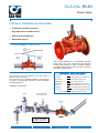
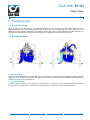
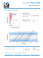
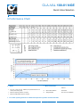
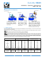
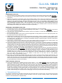
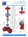
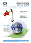
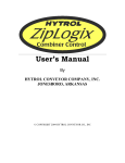
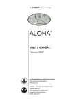
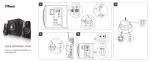
Fluid Handling Solutions: Automatic Control Valves CLA-VAL 81-01 Technical Documentation • Engineering Capabilities • Industry Experience • Certification & Approvals • Typical Applications • Global Operations • Markets & Applications ` Table of Contents • Main Function & Application • Schematic Diagram • Operating Data • Main Valve Description • Dimensions • Installation & Maintenance • Controls & Accessories • Valve Specification Form ` CLA-VAL Europe www.cla-val.ch [email protected] © Copyright CLA-VAL Europe - Specifications subject to change without notice - no contractual illustrations. 081001NE A 10/09 CLA-VAL 81-01 Check Valve ` Simple, Reliable and Accurate • Completely Automatic Operation • Easy Adjustment and Maintenance • Quality Approved Materials • World Wide Support ` CLA-VAL SERIES 81 Main Function The CLA-VAL SERIES 81 is a hydraulically operated Check Valve. The valve opens when inlet pressure exceeds outlet pressure. In case of reversal pressure, the higher outlet pressure closes the valve to prevent backflow through the valve. Make your Valve even Better! ` CLA-VAL 81-01 Typical Application The CLA-VAL 81-01 is designed to be used when a positive shut-off is required. The CLA-VAL 81-01 is typically installed on the discharge of pumps or well pumping systems to prevent backflow when the pump is off. Installation: Reverse Flow LFS Option? Control Low flows or night flows KO Option? Extend valve life with Anti-Cavitation trim KG1 Option? Use stem cleaning for harsh water Maintenance? Check on periodic maintenance Environment? Adapt to high temperatures or frost risk Security? Add hydraulic safety back-up to your valve Protection? Remove excessive system overpressures Corrosion? Protect your valve with upgraded materials Not just Products but Solutions: contact CLA-VAL! Pump Pump Control Valve CLA-VAL 60-31/02 CLA-VAL 81-01 Recommended typical assembly for CLA-VAL automatic control valves ` CLA-VAL Europe www.cla-val.ch [email protected] © Copyright CLA-VAL Europe - Specifications subject to change without notice - no contractual illustrations. 1 - 081001DE B 12/09 CLA-VAL 81-01 Check Valve ` Operating data 1.1 ` SHUT-OFF VALVE When the valve is normally operating, the differential between the inlet pressure P1 and the outlet pressure P2 is the differential pressure (P1 higher than P2) drop through the main valve (1). This differential is the force which pushes the diaphragm and disc assembly against the cover chamber and the main valve (1) opens gradually. If the inlet pressure P1 is lower than the outlet pressure P2 than the force pushed the disc against the seat and closes the valve (1). 1.2 ` OPERATING MODE 1.2.1 ` VALVE OPEN In this case, the inlet pressure P1 is higher than the oulet pressure P2. The force pushes the diaphragm and disc assembly against the cover chamber and opens the main valve (1). The main valve modulates until the complete opening position in response to changes in flow and pressure. 1.2.2 ` VALVE CLOSED In this case, the inlet pressure P1 is lower than the oulet pressure P2. The main valve (1) immediately responds and closes the main valve. The valve remains closed until the inlet pressure P1 is again higher than the outlet pressure P2. ` CLA-VAL Europe www.cla-val.ch [email protected] 1 - 081001CE A 12/08 CLA-VAL 100-01 NGE Main Valve HYTROL ` Simple, Reliable and Accurate ` CLA-VAL SERIES 100 Main Function Cover The CLA-VAL 100-01 HYTROL Valve is a hydraulically operated, diaphragm actuated, globe or angle pattern valve. It consists of three major components: body, diaphragm assembly and cover. The diaphragm assembly is the only moving part, guided top and bottom by a precision machined stem. The disc retainer and rubber disc form a drip-tight seal with the renewable seat when pressure is applied above the diaphragm (cover chamber). The CLA-VAL 100-01 is the basic valve used in nearly in all CLA-VAL Automatic Control Valves. Disc retain & Rubber disc Diaphragm There are 3 HYTROL body types: NGE: New Globe Execution GE: Globe Execution AE: Angle Execution Seat Stem Diaphragm assembly Body ` CLA-VAL 100-01 Principle of Operation CLA-VAL Controls On/Off Control On/Off Control Full Open Operation: When pressure in the cover chamber is relieved to a lower pressure or to atmosphere, the pressure inlet opens the valve. Tight Closing Operation: When pressure from the inlet pressure is applied to the cover chamber, the valve closes drip-tight. ` Usual Main Valves HYTROL Main Valve / HYTROL NGE-316 Modulating Control: The valve is pressure operating balanced. The CLA-VAL "Modulating" Controls will allow the valve to automatically compensate for pressure changes. ` More Information 100-01 Sheet # TYTAN Main Valve 100-01 5 Schematic Diagram HYTROL Auxiliary Valve 000130TT 5 Quick Valve Selection 000121DE ROLL SEAL Main Valve 100-42 5 Dimensions 000122DE-1 DELUGE Main Valve 100G 5 Pressure Ratings & Materials 000123DE HYN001TT ` Other Functions : Please Contact CLA-VAL ` CLA-VAL Europe www.cla-val.ch [email protected] 1 - HYN001DE B 01/08 CLA-VAL 100-01 NGE Quick Valve Selection ` Cavitation / Flow Chart ` Notes ` More Information Sheet # • Diagram to be used as a guide only. 5 Quick Valve Selection 000121DE 5 Sizing Software Run CLA-VAL Softwares ` To obtain a more accurate calculation please contact CLA-VAL ` CLA-VAL Europe www.cla-val.ch [email protected] 1 - 000121DE E 11/08 CLA-VAL 100-01 NGE Quick Valve Selection ` Performance Chart ` Notes ` More Information Sheet # • • Kv or Cv = m3/h or l/s @ 100kPa (1 bar) head loss with 15°C water (valve totally open). Minimum Opening Pressure: 0,2 [bar]. • Minimum Differential Pressure: 0,5 [bar]. 5 Quick Valve Selection 000121DE 5 Sizing Software Run CLA-VAL Softwares ` For lower opening Pressure or differential pressure, please contact CLA-VAL ` CLA-VAL Europe www.cla-val.ch [email protected] 2 - 000121DE E 11/08 ® CLA-VAL 100-01 NGE Dimensions TM H1 H Hm Stem ØC L Approx. outer limits of pilot-system B Approximate weight Complete Valve: 100% ØF Cover =20% A Trim =20% Body =60% Technical Data: Flanged (mm) L F H H1 (PN10) H1 (PN16) H1 (PN25) Hm A B øC Weight (Kg) DN 50 230 145 195 82.5 82.5 82.5 255 190 145 45 15 DN 65 290 170 225 93 93 93 295 200 150 60 20 DN 80 310 170 230 100 100 100 300 200 150 60 25 DN 100 DN 125 DN 150 DN 200 DN 250 DN 300 DN 350 DN 400 DN 450 DN 500 DN 600 350 400 480 600 730 850 980 1100 1200 1250 1450 235 295 295 400 510 600 900 900 712 712 712 305 365 375 460 547 695 821 821 900 1035 1035 110 125 142.5 170 200 227.5 252.5 282.5 325 370 430 110 125 142.5 170 200 227.5 260 290 325 370 430 117.5 135 150 180 212.5 242.5 277.5 310 335 370 430 390 470 480 585 700 875 1030 1030 1200 1310 1310 200 235 250 270 290 365 400 425 450 520 520 160 160 165 200 200 345 385 380 420 460 460 60 60 80 80 80 80 80 80 80 120 40 60 70 120 190 330 540 640 700 980 1060 DN 65 43 12 DN 80 58 16 DN 100 DN 125 DN 150 DN 200 DN 250 DN 300 DN 350 DN 400 DN 450 DN 500 DN 600 119 162 209 479 799 1292 1638 1789 2070 3049 3222 33 45 58 133 359 455 497 575 847 895 222 Hydraulic Data: Flanged (mm) Kv (m3/h) Cv (l/s) DN 50 32 9 Kv or Cv = m3/h or l/s @ 100kPa (1 bar) head loss with 15°C water (valve totally open). CLA-VAL Europe www.cla-val.ch [email protected] 1 - 000122DE-1 C 07/06 CLA-VAL 100-01 NGE Pressure Ratings & Materials PN10 - PN16 - PN25 ` DN 50 to DN 600 Standard Materials (3) Stud nut Stainless Steel (29) Washer Stainless Steel (6) Cover Ductile Iron (9) Diaphragm Reinforced Rubber (11) Disc guide Stainless Steel (14) Stem Stainless Steel (15) Seat Stainless Steel (4) Stud Stainless Steel (16) Body Ductile Iron • • • ` CLA-VAL Europe www.cla-val.ch Other Pressure Rating on request: PN 40, ANSI 150, ANSI 300. Standard epoxy coating minimum 250 microns. Auxiliary Valve HYTROL 3/8’’, 1/2’’, 3/4’’, 1’’ see 000130TT. [email protected] 1 - 000123DE E 11/08 CLA-VAL 100-01 Installation - Operation - Maintenance NGE - GE - AE ` DESCRIPTION The CLA-VAL Model 100-01 HYTROL Valve is a main valve for CLA-VAL Automatic Control Valves. It is a hydraulically operated, diaphragm-actuated, globe or angle pattern valve. This valve consists of three major components; body, diaphragm assembly, and cover. The diaphragm assembly is the only moving part. The diaphragm assembly uses a diaphragm of nylon fabric bonded with synthetic rubber. A synthetic rubber disc, contained on three and one half sides by a disc retainer and disc guide, forms a seal with the valve seat when pressure is applied above the diaphragm. The diaphragm assembly forms a sealed chamber in the upper portion of the valve, separating operating pressure from line pressure. Illustration type GE ` INSTALLATION 1. Before valve is installed, pipe lines should be flushed of all chips, scale and foreign matter. 2. It is recommended that either gate or block valves be installed on both ends of the 100-01 HYTROL Valve to facilitate isolating the valve for preventive maintenance and repairs. 3. Place the valve in the line with flow through the valve in the direction indicated on the inlet nameplate. (See “Flow Direction” Section) 4. Allow sufficient room around valve to make adjustments and for disassembly. 5. CLA-VAL 100-01 HYTROL Valves operate with maximum efficiency when mounted in horizontal piping with the cover UP, however, other positions are acceptable. Due to size and weight of the cover and internal components of 8 inch and larger valves, installation with the cover UP is advisable. This makes internal parts readily accessible for periodic inspection. 6. Caution must be taken in the installation of this valve to insure that galvanic and/or electrolytic action does not take place. The proper use of dielectric fittings and gaskets are required in all systems using dissimilar metals. 7. If a pilot control system is installed on the 100-01 HYTROL Valve, use care to prevent damage. If it is necessary to remove fittings or components, be sure they are kept clean and replaced exactly as they were. 8. After the valve is installed and the system is first pressurized, vent air from the cover chamber and pilot system tubing by loosening fittings at all high points. ` FLOW DIRECTION The flow through the 100-01 HYTROL Valve can be in one of two directions. When flow is “up-and-over the seat,” it is in “normal” flow and the valve will fail in the open position. When flow is “over the seat-and down,” it is in “reverse” flow and the valve will fail in the closed position. There are no permanent flow arrow markings. The valve must be installed according to nameplate data. BRIDGEWALL INDICATOR (cast into side of valve body) ` RECOMMENDED TOOLS 1. Three pressure gauges with ranges suitable to the installation to be put at HYTROL inlet, outlet and cover connections. 2. CLA-VAL Model X101 Valve Position Indicator. This provides visual indication of valve position without disassembly of valve. 3. Other items are: suitable hand tools such as screwdrivers, wrenches, etc. soft jawed (brass or aluminum) vise 400 grit wet or dry sandpaper and water for cleaning. ` CLA-VAL Europe www.cla-val.ch [email protected] 1 - HYT001SE C 11/08 CLA-VAL 100-01 Installation - Operation - Maintenance NGE - GE - AE ` PRINCIPLES OF OPERATION CLA-VAL control (Illustration type GE) On/Off Control On/Off Control Tight Closing Operation Full Open Operation Modulating Action When pressure from the valve inlet (or an equivalent independent operating pressure) is applied to the diaphragm chamber the valve closes drip-tight. When pressure in diaphragm chamber is relieved to a zone of lower pressure (usually atmosphere) the line pressure (5 psi Min.) at the valve inlet opens the valve. Valve modulates when diaphragm pressure is held at an intermediate point between inlet and discharge pressure. With the use of a CLA-VAL. "modulating control," which reacts to line pressure changes, the pressure above the diaphragm is varied, allowing the valve to throttle and compensate for the change. ` THREE CHECKS The 100-01 HYTROL Valve has only one moving part (the diaphragm and disc assembly). So, there are only three major types of problems to be considered. First: Valve is stuck - that is, the diaphragm assembly is not free to move through a full stroke either from open to close or vice versa. Second: Valve is free to move and can’t close because of a worn out diaphragm. Third: Valve leaks even though it is free to move and the diaphragm isn’t leaking. CAUTION! Care should be taken when doing the troubleshooting checks on the 100-01 HYTROL Valve. These checks do require the valve to open fully. This will either allow a high flow rate through the valve, or the downstream pressure will quickly increase to the inlet pressure. In some cases, this can be very harmful. Where this is the case, and there are no block valves in the system to protect the downstream piping, it should be realized that the valve cannot be serviced under pressure. Steps should be taken to remedy this situation before proceeding any further. Valve size (DN) NGE 50 65 & 80 GE 32 - 40 50 65 80 100 150 200 250 300 350 400 100 125 & 150 200 250 300 350 & 400 500 & 600 TYTAN TYTAN-S TYTAN-M TYTAN-L ` CLA-VAL Europe 600 - 800 900 - 1000 900 - 1200 COVER CHAMBER CAPACITY (liquid Volume displaced when valve opens) Liters Gallons 0,07 0,020 0,12 0,032 0,16 0,043 0,30 0,080 0,64 0,169 2,00 0,531 4,80 1,260 9,50 2,510 15,10 4,000 24,60 6,500 36,20 9,570 Liters 107,00 159,00 340,00 www.cla-val.ch Gallons 28,27 42,00 90,00 [email protected] STEM TRAVEL (Fully Open To Fully closed) mm Inches 10,0 0,40 15,0 0,60 18,0 0,70 20,0 0,80 28,0 1,10 43,0 1,70 58,0 2,30 71,0 2,80 86,0 3,40 100,0 4,00 114,0 4,50 mm 154,6 190,0 216,0 Inches 6,0 7,5 8,5 2 - HYT001SE C 11/08 CLA-VAL 100-01 Installation - Operation - Maintenance NGE - GE - AE DIAPHRAGM CHECK (#1) 1. Shut off pressure to the HYTROL Valve by slowly closing upstream and downstream isolation valves. SEE CAUTION!. 2. Disconnect or close all pilot control lines to the valve cover and leave only one fitting in highest point of cover open to atmosphere. 3. With the cover vented to atmosphere, slowly open upstream isolation valve to allow some pressure into the HYTROL Valve body. Observe the open cover tapping for signs of continuous flow. It is not necessary to fully open isolating valve. Volume in cover chamber capacity chart will be displaced as valve moves to open position. Allow sufficient time for diaphragm assembly to shift positions. If there is no continuous flow, you can be quite certain the diaphragm is sound and the diaphragm assembly is tight. If the fluid appears to flow continuously this is a good reason to believe the diaphragm is either damaged or it is loose on the stem. In either case, this is sufficient cause to remove the valve cover and investigate the leakage. (See “Maintenance” Section for procedure.) FREEDOM OF MOVEMENT CHECK (#2) 4. Determining the HYTROL Valve’s freedom of movement can be done by one of two methods. 5. For most valves it can be done after completing Diaphragm Check (Steps 1., 2., and 3.). SEE CAUTION!. At the end of step 3. the valve should be fully open. 6. If the valve has a CLA-VAL X101 Position Indicator, observe the indicator to see that the valve opens wide. Mark the point of maximum opening. 7. Re-connect enough of the control system to permit the application of inlet pressure to the cover. Open pilot system cock so pressure flows from the inlet into the cover. 8. While pressure is building up in the cover, the valve should close smoothly. There is a hesitation in every HYTROL Valve closure, which can be mistaken for a mechanical bind. The stem will appear to stop moving very briefly before going to the closed position. This slight pause is caused by the diaphragm flexing at a particular point in the valve’s travel and is not caused by a mechanical bind. 9. When closed, a mark should be made on the X101 Valve position indicator corresponding to the “closed” position. The distance between the two marks should be approximately the stem travel shown in chart. 10. If the stroke is different than that shown in stem travel chart this is a good reason to believe something is mechanically restricting the stroke of the valve at one end of its travel. If the flow does not stop through the valve when in the indicated “closed” position, the obstruction probably is between the disc and the seat. If the flow does stop, then the obstruction is more likely in the cover. In either case, the cover must be removed, and the obstruction located and removed. The stem should also be checked for scale build-up. (See “Maintenance, section for procedure.) 11. For valves 6” and smaller, the HYTROL Valve’s freedom of movement check can also be done after all pressure is removed from the valve. SEE CAUTION!. After closing inlet and outlet isolation valves and bleeding pressure from the valve, check that the cover chamber and the body are temporarily vented to atmosphere. Insert fabricated tool into threaded hole in top of valve stem, and lift the diaphragm assembly manually. Note any roughness. The diaphragm assembly should move smoothly throughout entire valve stroke. The tool is fabricated from rod that is threaded on one end to fit valve stem and has a “T” bar handle of some kind on the other end for easy gripping. (See chart in Step 4 of “Disassembly” Section.) 12. Place marks on this diaphragm assembly lifting tool when the valve is closed and when manually positioned open. The distance between the two marks should be approximately the stem travel shown in stem travel chart. If the stroke is different than that shown, there is a good reason to believe something is mechanically restricting the stroke of the valve. The cover must be removed, and the obstruction located and removed. The stem should also be checked for scale buildup. (See “Maintenance, section for procedure.) TIGHT SEALING CHECK (#3) 13. Test for seat leakage after completing checks #1 & #2 (Steps 1. to 12.). SEE CAUTION!. Close the isolation valve downstream of the HYTROL Valve. Apply inlet pressure to the cover of the valve, wait until it closes. Install a pressure gauge between the two closed valves using one of the two ports in the outlet side of the HYTROL. Watch the pressure gauge. If the pressure begins to climb, then either the downstream isolation valve is permitting pressure to creep back, or the HYTROL is allowing pressure to go through it. Usually the pressure at the HYTROL inlet will be higher than on the isolation valve discharge, so if the pressure goes up to the inlet pressure, you can be sure the HYTROL is leaking. Install another gauge downstream of isolating valve. If the pressure between the valves only goes up to the pressure on the isolation valve discharge, the HYTROL Valve is holding tight, and it was just the isolation valve leaking. ` TROUBLESHOOTING The following troubleshooting information deals strictly with the Model 100-01 HYTROL Valve. This assumes that all other components of the pilot control system have been checked out and are in proper working condition. (See appropriate sections in Technical Manual for complete valve). ` CLA-VAL Europe www.cla-val.ch [email protected] 3 - HYT001SE C 11/08 CLA-VAL 100-01 Installation - Operation - Maintenance NGE - GE - AE All trouble shooting is possible without removing the valve from the line or removing the cover. It is highly recommended to permanently install a Model X101 Valve Position Indicator and three gauges in unused HYTROL inlet, outlet and cover connections. SYMPTOM Fails to close Fails to open PROBABLE CAUSE Closed isolation valves in control system, or in main line. Lack of cover chamber pressure. Diaphragm damaged. (See Diaphragm Check) Diaphragm assembly inoperative. Corrosion or excessive scale build-up on valve stem. (See Freedom of Movement Check) Mechanical obstruction. Object lodged in valve. (See Freedom of Movement Check) Worn disc. (See Tight Sealing Check) Badly scored seat. (See Tight Sealing Check) Closed upstream and/or downstream isolation valves in main line. Insufficient line pressure. Diaphragm assembly inoperative. Corrosion or excessive build-up on valve stem. (See Freedom of Movement Check) Diaphragm damaged. (For valves in "reverse flow" only) REMEDY Open Isolation valves. Check upstream pressure, pilot system, strainer, tubing, valves, or needle valves for obstruction. Replace diaphragm. Clean and polish stem. Inspect and replace any damaged or badly eroded part. Remove obstruction. Replace disc. Replace seat. Open isolation valves. Check upstream pressure. (Minimum 5 psi flowing line pressure differential.) Clean and polish stem. Inspect and replace any damaged or badly eroded part. Replace diaphragm. After checking out probable causes and remedies, the following three checks can be used to diagnose the nature of the problem before maintenance is started. They must be done in the order shown. ` MAINTENANCE PREVENTATIVE MAINTENANCE The CLA-VAL Model 100-01 HYTROL Valve requires no lubrication or packing and a minimum of maintenance. However, a periodic inspection schedule should be established to determine how the operating conditions of the system are affecting the valve. The effect of these actions must be determined by inspection. DISASSEMBLY Inspection or maintenance can be accomplished without removing the valve from the line. Repair kits with new diaphragm and disc are recommended to be on hand before work begins. : Maintenance personnel can be injured and equipment damaged if disassembly is attempted with pressure in the valve. SEE CAUTION!. 1. Close upstream and downstream isolation valves and independent operating pressure when used to shut off all pressure to the valve. 2. Loosen tube fittings in the pilot system to remove pressure from valve body and cover chamber. After pressure has been released from the valve, use care to remove the controls and tubing. Note and sketch position of tubing and controls for re-assembly. The schematic in front of the Technical Manual can be used as a guide when reassembling pilot system. 3. Remove cover nuts and remove cover. If the valve has been in service for any length of time, chances are the cover will have to be loosened by driving upward along the edge of the cover with a dull cold chisel. ` CLA-VAL Europe www.cla-val.ch [email protected] 4 - HYT001SE C 11/08 CLA-VAL 100-01 Installation - Operation - Maintenance NGE - GE - AE On 6” and smaller valves block and tackle or a power hoist can be used to lift valve cover by inserting proper size eye bolt in place of the center cover plug. On 8” and larger valves there are 4 holes (5/8” - 11 size) where jacking screws and/or eye bolts may be inserted for lifting purposes. Pull cover straight up to keep from damaging the integral seat bearing and stem. COVER CENTER PLUG SIZE Valve size Thread Size (NPT) NGE GE / AE DN 50 DN 32 - 40 1/4" DN 65 - 100 DN 50 - 80 1/2" DN 125 - 200 DN 100 - 150 3/4" DN 250 - 300 DN 200 - 250 1" DN 650 - 400 DN 300 1 1/4" DN 350 1 1/2" DN 500 - 600 DN 400 2" TYTAN-S TYTAN-M TYTAN-L DN 600 - 800 DN 900 - 1000 DN 900 - 1200 1" 2" 2" 4. Remove the diaphragm and disc assembly from the valve body. With smaller valves this can be accomplished by hand by pulling straight up on the stem so as not to damage the seat bearing. On large valves, an eye bolt of proper size can be installed in the stem and the diaphragm assembly can be then lifted with a block and tackle or power hoist. Take care not to damage the stem or bearings. The valve won't work if these are damaged. VALVE STEM THREAD SIZE Valve size Thread Size (Internal) NGE GE / AE DN 50 - 80 DN 32 - 65 10 - 32 UNF DN 100 - 150 DN 80 - 100 1/4 - 28 UNF DN 200 - 400 DN 150 - 350 3/8 - 24 UNF DN 500 - 600 DN 400 1/2 - 20 UNF TYTAN-S TYTAN-M TYTAN-L DN 600 - 800 DN 900 - 1000 DN 900 - 1200 1/2 - 20 UNF M20 M20 5. The next item to remove is the stem nut. Examine the stem threads above the nut for signs of mineral deposits or corrosion. If the threads are not clean, use a wire brush to remove as much of the residue as possible. Attach a good fitting wrench to the nut and give it a sharp “rap” rather than a steady pull. Usually several blows are sufficient to loosen the nut for further removal. On the smaller valves, the entire diaphragm assembly can be held by the stem in a vise equipped with soft brass jaws before removing the stem nut. The use of a pipe wrench or a vise without soft brass jaws scars the fine finish on the stem. No amount of careful dressing can restore the stem to its original condition. Damage to the finish of the stem can cause the stem to bind in the bearings and the valve will not open or close. 6. After the stem nut has been removed, the diaphragm assembly breaks down into its component parts. Removal of the disc from the disc retainer can be a problem if the valve has been in service for a long time. Using two screwdrivers inserted along the outside edge of the disc usually will accomplish its removal. Care should be taken to preserve the spacer washers in water, particularly if no new ones are available for re-assembly. 7. The only part left in the valve body is the seat which ordinarily does not require removal. Careful cleaning and polishing of inside and outside surfaces with 400 wet/dry sandpaper will usually restore the seat’s sharp edge. If, however, it is badly worn and replacement is necessary, it can be easily removed. Seats in valve sizes 1 1/4” through 6” are threaded into the valve body. They can be removed with accessory X109 Seat Removing Tool available from the factory. On 8” and larger valves, the seat is held in place by flat head machine screws. Use a tight-fitting, long shank screwdriver to prevent damage to seat screws. If upon removal of the screws the seat cannot be lifted out, it will be necessary to use a piece of angle or channel iron with a hole drilled in the center. Place it across the body so a long stud can be inserted through the center hole in the seat and the hole in the angle iron. By tightening the nut a uniform upward force is exerted on the seat for removal. Note: Do not lift up on the end of the angle iron as this may force the integral bearing out of alignment, causing the stem to bind. ` CLA-VAL Europe www.cla-val.ch [email protected] 5 - HYT001SE C 11/08 CLA-VAL 100-01 Installation - Operation - Maintenance NGE - GE - AE INSPECTION OF PARTS After the valve has been disassembled, each part should be examined carefully for signs of wear, corrosion, or any other abnormal condition. Usually, it is a good idea to replace the rubber parts (diaphragm and disc) unless they are free of signs of wear. These are available in a repair kit. Any other parts which appear doubtful should be replaced. WHEN ORDERlNG PARTS, BE SURE TO GIVE COMPLETE NAMEPLATE DATA, ITEM NUMBER AND DESCRlPTlON. Note: If a new disc isn’t available, the existing disc can be turned over, exposing the unused surface for contact with the seat. The disc should be replaced as soon as practical. REASSEMBLY 1. Reassembly is the reverse of the disassembly procedure. If a new disc has been installed, it may require a different number of spacer washers to obtain the right amount of “grip” on the disc. When the diaphragm assembly has been tightened to a point where the diaphragm cannot be twisted, the disc should be compressed very slightly by the disc guide. Excessive compression should be avoided. Use just enough spacer washers to hold the disc firmly without noticeable compression. 2. MAKE SURE THE STEM NUT IS VERY TIGHT. Attach a good fitting wrench to the nut and give it a sharp “rap” rather than a steady pull. Usually several blows are sufficient to tighten the stem nut for final tightening. Failure to do so could allow the diaphragm to pull loose and tear when subjected to pressure. 3. Carefully install the diaphragm assembly by lowering the stem through the seat bearing. Take care not to damage the stem or bearing. Line up the diaphragm holes with the stud or bolt holes on the body. On larger valves with studs, it may be necessary to hold the diaphragm assembly up part way while putting the diaphragm over the studs. 4. Put spring in place and replace cover. Make sure diaphragm is Iying smooth under the cover. 5. Tighten cover nuts firmly using a cross-over pattern until all nuts are tight. 6. Test HYTROL Valve before re-installing pilot valve system. TEST PROCEDURE AFTER VALVE ASSEMBLY There are a few simple tests which can be made in the field to make sure the HYTROL Valve has been assembled properly. Do these before installing pilot system and returning valve to service. These are similar to the three troubleshooting tests. 1- Check the diaphragm assembly for freedom of movement after all pressure is removed from the valve. SEE CAUTlON!. Insert fabricated tool into threaded hole in top of valve stem, and lift the diaphragm assembly manually. Note any roughness, sticking or grabbing. The diaphragm assembly should move smoothly throughout entire valve stroke. The tool is fabricated from rod that is threaded on one end to fit valve stem (See chart in Step 4 of “Disassembly” section.) and has a “T” Bar handle of some kind on the other end for easy gripping. Place marks on this diaphragm assembly lifting tool when the valve is closed and when manually positioned open. The distance between the two marks should be approximately the stem travel shown in stem travel chart. (See “Freedom of Movement Check” section.) If the stroke is different than that shown, there is a good reason to believe something is mechanically restricting the stroke of the valve. The cover must be removed, the obstruction located and removed. (See “Maintenance” Section for procedure.) Due to the weight of the diaphragm assembly this procedure is not possible on valves 8” and larger. on these valves, the same determination can be made by carefully introducing a low pressure-less than five psi) into the valve body with the cover vented. SEE CAUTION!. Looking in cover center hole see the diaphragm assembly lift easily without hesitation, and then settle back easily when the pressure is removed. 2- To check the valve for drip-tight closure, a line should be connected from the inlet to the cover, and pressure applied at the inlet of the valve. If properly assembled, the valve should hold tight with as low as ten PSI at the inlet. See “Tight Sealing Check” section.) 3- With the line connected from the inlet to the cover, apply full working pressure to the inlet. Check all around the cover for any leaks. Re-tighten cover nuts if necessary to stop leaks past the diaphragm. 4- Remove pressure, then re-install the pilot system and tubing exactly as it was prior to removal. Bleed air from all high points. 5- Follow steps under “Start-Up and Adjustment” Section in Technical Manual for returning complete valve back to service. ` CLA-VAL Europe www.cla-val.ch [email protected] 6 - HYT001SE C 11/08 ® TM CLA-VAL 100-01 NGE Vanne de base - Main Valve – Hauptventil Ecrou Nut Mutter 3 29 21 Rondelle Washer Scheibe 30 18 6 Chapeau Cover Deckel 5 Palier de chapeau Cover bearing Deckellager 19 6 5 Ressort 17 Joint torique O-ring O-ring Spring Feder 7 Ecrou d'axe Stem nut Stösselmutter 8 Rondelle de membrane Diaphragm washer Membranscheibe 20* Joint torique O-ring O-ring 9* Membrane Diaphragm Membrane 12 Porte-joint Disc retainer Dichtungsträger 10* Cale d'épaisseur Space washer Toleranzscheibe 13* Joint de siège disc Dichtung 11 Contre-siège Disc guide Gegensitz 23 14 Axe Stem Stössel 15 Siège Seat Sitz NGE DN 500 - DN 600 23 Joint torique O-ring O-ring Vis 22 Screw Schraube 15 4 Goujon Stud Gewindebolzen 16 Corps Body Gehäuse NGE DN 250 - DN 600 * = CLA-KIT NGE DN 50 - DN 200 CLA-VAL Europe www.cla-val.ch [email protected] 1 - HYN001TT D 03/07 CLA-VAL 100-01 NGE DN 50 PN 10 - 16 - 25 ` STD: STANDARD PIECE DE RECHANGE / SPARE PARTS / ERSATZTEILE KIT DE REPARATION / REPAIR KIT / REPARATURSATZ (a) CLA-KIT HYTROL100-01 - GE 40/PN 10 - 16 (b) CLA-KIT HYTROL100-01 - GE 40/PN 25 POS. 1 2 3 4 5 6 7 8 9 9.1 10 11 12 13 13.1 14 15 16 17 17.1 20 23 25 29 DESCRIPTION Bouchon-purgeur Bouchon Ecrou Goujon Palier de chapeau Chapeau Ecrou d’axe Rondelle de membrane Membrane Membrane (PN25) Cale d’épaisseur Contre-siège Porte-joint Joint de siège Joint de siège (***) Axe Siège Corps Ressort Ressort renforcé (PN25) Joint torique Joint torique Bouchon Rondelle plate DESCRIPTION Air release plug Cover plug Stud nut Stud Cover bearing Cover Stem nut Diaphragm washer Diaphragm Diaphragm (PN25) Space washer Disc guide Disc retainer Disc Disc (***) Stem Seat Body Spring Spring heavy (PN25) O-ring O-ring Plug Washer BESCHREIBUNG Entlüftungstopfen Stopfen Mutter Gewindebolzen Deckellager Deckel Stösselmutter Membranscheibe Membrane Membrane (PN25) Toleranzscheibe Gegensitz Dichtungsträger Dichtung Dichtung (***) Stössel Sitz Gehäuse Feder Verstärkte Feder (PN25) O-Ring O-Ring Stopfen Unterlegscheibe 91698-04 CLA-VAL MAT. 303 316 303 303 303 FD4 303 PLA RBR RBR FIB 316 303 RBR PET 303 316 FD4 302 302 RBR RBR 316 303 CLA-VAL Nr. 57576 BGT2001 67799-08A 57621-01 57933 57185-40 89375-01J 2960701H 83239E (a) 83239E (2x) (b) V-5180E (a/b) C-5446E C-1862G V-5562D (a/b) 21589-01F (b***) 57286 C-1425C (**) C-8477G C-8476G 00713J (a/b) 00731A BGT2001 67747-04J (**) Voir / See / Siehe HYT016F (***) Recommandé si ∆P>16 bar / Recommended if ∆P>16 bar / Empfohlen wenn ∆P>16 bar KC: KCO: KCS: KCOS: Revêtement époxy / Standard epoxy coating / Epoxy-Pulverbeschichtung (minimum 250 µm) KC + Visserie en acier inoxydable / Stainless steel bolts / Deckelschrauben aus Edelstahl KC + Siège et contre-siège en acier inoxydable / Stainless steel seat and guide / Sitz und Gegensitz aus Edelstahl KCO + KCS. ` CLA-VAL Europe www.cla-val.ch [email protected] 1 - HYN001LT - 09/08 CLA-VAL 100-01 NGE DN 65 PN 10 - 16 - 25 ` STD: STANDARD PIECE DE RECHANGE / SPARE PARTS / ERSATZTEILE KIT DE REPARATION / REPAIR KIT / REPARATURSATZ (a) CLA-KIT HYTROL100-01 - GE 50/PN 10 - 16 (b) CLA-KIT HYTROL100-01 - GE 50/PN 25 POS. 1 2 3 4 5 6 7 8 9 9.1 10 11 12 13 13.1 14 15 16 17 17.1 20 23 25 29 DESCRIPTION Bouchon-purgeur Bouchon Ecrou Goujon Palier de chapeau Chapeau Ecrou d’axe Rondelle de membrane Membrane Membrane (PN25) Cale d’épaisseur Contre-siège Porte-joint Joint de siège Joint de siège (***) Axe Siège Corps Ressort Ressort renforcé (PN25) Joint torique Joint torique Bouchon Rondelle plate DESCRIPTION Air release plug Cover plug Stud nut Stud Cover bearing Cover Stem nut Diaphragm washer Diaphragm Diaphragm (PN25) Space washer Disc guide Disc retainer Disc Disc (***) Stem Seat Body Spring Spring heavy (PN25) O-ring O-ring Plug Washer BESCHREIBUNG Entlüftungstopfen Stopfen Mutter Gewindebolzen Deckellager Deckel Stösselmutter Membranscheibe Membrane Membrane (PN25) Toleranzscheibe Gegensitz Dichtungsträger Dichtung Dichtung (***) Stössel Sitz Gehäuse Feder Verstärkte Feder (PN25) O-Ring O-Ring Stopfen Unterlegscheibe 91698-05 CLA-VAL MAT. 303 316 303 303 303 FD4 303 PLA RBR RBR FIB 316 303 RBR PET 303 316 FD4 302 316 RBR RBR 316 303 CLA-VAL Nr. 57576 BGT2001 67801-08E 57621-02 57934 57186-40 89376-01G 2665501K 80522G (a) C-1493-01 (b) V-5232D (a/b) 32560F 57383-01 V-5564K (a/b) 21265-01C (b***) 57287 C-4135-01C (**) C-3147A C-3152A 00714G (a/b) 00775H BGT2001 67748-04G (**) Voir / See / Siehe HYT016F (***) Recommandé si ∆P>16 bar / Recommended if ∆P>16 bar / Empfohlen wenn ∆P>16 bar KC: KCO: KCS: KCOS: Revêtement époxy / Standard epoxy coating / Epoxy-Pulverbeschichtung (minimum 250 µm) KC + Visserie en acier inoxydable / Stainless steel bolts / Deckelschrauben aus Edelstahl KC + Siège et contre-siège en acier inoxydable / Stainless steel seat and guide / Sitz und Gegensitz aus Edelstahl KCO + KCS. ` CLA-VAL Europe www.cla-val.ch [email protected] 1 - HYN002LT - 09/08 CLA-VAL 100-01 NGE DN 80 PN 10 - 16 - 25 ` STD: STANDARD PIECE DE RECHANGE / SPARE PARTS / ERSATZTEILE KIT DE REPARATION / REPAIR KIT / REPARATURSATZ (a) CLA-KIT HYTROL100-01 - GE 50/PN 10 - 16 (b) CLA-KIT HYTROL100-01 - GE 50/PN 25 POS. 1 2 3 4 5 6 7 8 9 9.1 10 11 12 13 13.1 14 15 16 17 17.1 20 23 25 29 DESCRIPTION Bouchon-purgeur Bouchon Ecrou Goujon Palier de chapeau Chapeau Ecrou d’axe Rondelle de membrane Membrane Membrane (PN25) Cale d’épaisseur Contre-siège Porte-joint Joint de siège Joint de siège (***) Axe Siège Corps Ressort Ressort renforcé (PN25) Joint torique Joint torique Bouchon Rondelle plate DESCRIPTION Air release plug Cover plug Stud nut Stud Cover bearing Cover Stem nut Diaphragm washer Diaphragm Diaphragm (PN25) Space washer Disc guide Disc retainer Disc Disc (***) Stem Seat Body Spring Spring heavy (PN25) O-ring O-ring Plug Washer BESCHREIBUNG Entlüftungstopfen Stopfen Mutter Gewindebolzen Deckellager Deckel Stösselmutter Membranscheibe Membrane Membrane (PN25) Toleranzscheibe Gegensitz Dichtungsträger Dichtung Dichtung (***) Stössel Sitz Gehäuse Feder Verstärkte Feder (PN25) O-Ring O-Ring Stopfen Unterlegscheibe 91698-05 CLA-VAL MAT. 303 316 303 303 303 FD4 303 PLA RBR RBR FIB 316 303 RBR PET 303 316 FD4 302 316 RBR RBR 316 303 CLA-VAL Nr. 57576 BGT2001 67801-08E 57621-02 57934 57186-40 89376-01G 2665501K 80522G (a) C-1493-01 (b) V-5232D (a/b) 32560F 57383-01 V-5564K (a/b) 21265-01C (b***) 57287 C-4135-01C (**) C-3147A C-3152A 00714G (a/b) 00775H BGT2001 67748-04G (**) Voir / See / Siehe HYT016F (***) Recommandé si ∆P>16 bar / Recommended if ∆P>16 bar / Empfohlen wenn ∆P>16 bar KC: KCO: KCS: KCOS: Revêtement époxy / Standard epoxy coating / Epoxy-Pulverbeschichtung (minimum 250 µm) KC + Visserie en acier inoxydable / Stainless steel bolts / Deckelschrauben aus Edelstahl KC + Siège et contre-siège en acier inoxydable / Stainless steel seat and guide / Sitz und Gegensitz aus Edelstahl KCO + KCS. ` CLA-VAL Europe www.cla-val.ch [email protected] 1 - HYN003LT - 09/08 CLA-VAL 100-01 NGE DN 100 PN 10 - 16 - 25 ` STD: STANDARD PIECE DE RECHANGE / SPARE PARTS / ERSATZTEILE KIT DE REPARATION / REPAIR KIT / REPARATURSATZ (a) CLA-KIT HYTROL100-01 - GE 80/PN 10 - 16 (b) CLA-KIT HYTROL100-01 - GE 80/PN 25 POS. 1 2 3 4 5 6 7 8 9 9.1 10 11 12 13 13.1 14 15 16 17 17.1 20 23 25 29 DESCRIPTION Bouchon-purgeur Bouchon Ecrou Goujon Palier de chapeau Chapeau Ecrou d’axe Rondelle de membrane Membrane Membrane (PN25) Cale d’épaisseur Contre-siège Porte-joint Joint de siège Joint de siège (***) Axe Siège Corps Ressort Ressort renforcé (PN25) Joint torique Joint torique Bouchon Rondelle plate DESCRIPTION Air release plug Cover plug Stud nut Stud Cover bearing Cover Stem nut Diaphragm washer Diaphragm Diaphragm (PN25) Space washer Disc guide Disc retainer Disc Disc (***) Stem Seat Body Spring Spring heavy (PN25) O-ring O-ring Plug Washer BESCHREIBUNG Entlüftungstopfen Stopfen Mutter Gewindebolzen Deckellager Deckel Stösselmutter Membranscheibe Membrane Membrane (PN25) Toleranzscheibe Gegensitz Dichtungsträger Dichtung Dichtung (***) Stössel Sitz Gehäuse Feder Verstärkte Feder (PN25) O-Ring O-Ring Stopfen Unterlegscheibe 91698-12 CLA-VAL MAT. 303 316 303 303 303 FD4 303 FTG RBR RBR FIB 316 FTG RBR PET 303 316 FD4 302 316 RBR RBR 316 303 CLA-VAL Nr. 57576-02 BGT3001 67805-08F 57621-04 57935 57188-40 89377-01E V-5447/KC 83241A (a) C-8262C (b) V-0631B (a/b) C-7389E V-5449/KC V-1734C (a/b) 21267-01J (b***) 57289 C-7391A (**) C-3149G C-1106J 00750A (a/b) 00788A BGT3001 67750-04C (**) Voir / See / Siehe HYT016F (***) Recommandé si ∆P>16 bar / Recommended if ∆P>16 bar / Empfohlen wenn ∆P>16 bar KC: KCO: KCS: KCOS: Revêtement époxy / Standard epoxy coating / Epoxy-Pulverbeschichtung (minimum 250 µm) KC + Visserie en acier inoxydable / Stainless steel bolts / Deckelschrauben aus Edelstahl KC + Siège et contre-siège en acier inoxydable / Stainless steel seat and guide / Sitz und Gegensitz aus Edelstahl KCO + KCS. ` CLA-VAL Europe www.cla-val.ch [email protected] 1 - HYN004LT - 09/08 CLA-VAL 100-01 NGE DN 125 PN 10 - 16 - 25 ` STD: STANDARD PIECE DE RECHANGE / SPARE PARTS / ERSATZTEILE KIT DE REPARATION / REPAIR KIT / REPARATURSATZ (a) CLA-KIT HYTROL100-01 - GE 100/PN 10 - 16 (b) CLA-KIT HYTROL100-01 - GE 100/PN 25 POS. 1 2 3 4 5 6 7 8 9 9.1 10 11 12 13 13.1 14 15 16 17 17.1 20 23 25 29 DESCRIPTION Bouchon-purgeur Bouchon Ecrou Goujon Palier de chapeau Chapeau Ecrou d’axe Rondelle de membrane Membrane Membrane (PN25) Cale d’épaisseur Contre-siège Porte-joint Joint de siège Joint de siège (***) Axe Siège Corps Ressort Ressort renforcé (PN25) Joint torique Joint torique Bouchon Rondelle plate DESCRIPTION Air release plug Cover plug Stud nut Stud Cover bearing Cover Stem nut Diaphragm washer Diaphragm Diaphragm (PN25) Space washer Disc guide Disc retainer Disc Disc (***) Stem Seat Body Spring Spring heavy (PN25) O-ring O-ring Plug Washer BESCHREIBUNG Entlüftungstopfen Stopfen Mutter Gewindebolzen Deckellager Deckel Stösselmutter Membranscheibe Membrane Membrane (PN25) Toleranzscheibe Gegensitz Dichtungsträger Dichtung Dichtung (***) Stössel Sitz Gehäuse Feder Verstärkte Feder (PN25) O-Ring O-Ring Stopfen Unterlegscheibe 91698-13 CLA-VAL MAT. 303 316 303 303 303 FD4 303 FTG RBR RBR FIB 316 FTG RBR PET 303 316 FD4 302 302 RBR RBR 316 303 CLA-VAL Nr. 57576-02 BGT4001 67811-08D 37048-02C 57936 57189-40 89378-01C V-5420/KC 86807F (a) C-8184J (b) V-0634F (a/b) 31052E V-5457/KC V-5467F (a/b) 21268-01G (b***) 57290 31053C (**) C-1533D C-1408J 00752G (a/b) 00836H BGT4001 67753-04G (**) Voir / See / Siehe HYT016F (***) Recommandé si ∆P>16 bar / Recommended if ∆P>16 bar / Empfohlen wenn ∆P>16 bar KC: KCO: KCS: KCOS: Revêtement époxy / Standard epoxy coating / Epoxy-Pulverbeschichtung (minimum 250 µm) KC + Visserie en acier inoxydable / Stainless steel bolts / Deckelschrauben aus Edelstahl KC + Siège et contre-siège en acier inoxydable / Stainless steel seat and guide / Sitz und Gegensitz aus Edelstahl KCO + KCS. ` CLA-VAL Europe www.cla-val.ch [email protected] 1 - HYN005LT - 09/08 CLA-VAL 100-01 NGE DN 150 PN 10 - 16 - 25 ` STD: STANDARD PIECE DE RECHANGE / SPARE PARTS / ERSATZTEILE KIT DE REPARATION / REPAIR KIT / REPARATURSATZ (a) CLA-KIT HYTROL100-01 - GE 100/PN 10 - 16 (b) CLA-KIT HYTROL100-01 - GE 100/PN 25 POS. 1 2 3 4 5 6 7 8 9 9.1 10 11 12 13 13.1 14 15 16 17 17.1 20 23 25 29 DESCRIPTION Bouchon-purgeur Bouchon Ecrou Goujon Palier de chapeau Chapeau Ecrou d’axe Rondelle de membrane Membrane Membrane (PN25) Cale d’épaisseur Contre-siège Porte-joint Joint de siège Joint de siège (***) Axe Siège Corps Ressort Ressort renforcé (PN25) Joint torique Joint torique Bouchon Rondelle plate DESCRIPTION Air release plug Cover plug Stud nut Stud Cover bearing Cover Stem nut Diaphragm washer Diaphragm Diaphragm (PN25) Space washer Disc guide Disc retainer Disc Disc (***) Stem Seat Body Spring Spring heavy (PN25) O-ring O-ring Plug Washer BESCHREIBUNG Entlüftungstopfen Stopfen Mutter Gewindebolzen Deckellager Deckel Stösselmutter Membranscheibe Membrane Membrane (PN25) Toleranzscheibe Gegensitz Dichtungsträger Dichtung Dichtung (***) Stössel Sitz Gehäuse Feder Verstärkte Feder (PN25) O-Ring O-Ring Stopfen Unterlegscheibe 91698-13 CLA-VAL MAT. 303 316 303 303 303 FD4 303 FTG RBR RBR FIB 316 FTG RBR PET 303 316 FD4 302 302 RBR RBR 316 303 CLA-VAL Nr. 57576-02 BGT4001 67811-08D 37048-02C 57936 57189-40 89378-01C V-5420/KC 86807F (a) C-8184J (b) V-0634F (a/b) 31052E V-5457/KC V-5467F (a/b) 21268-01G (b***) 57290 31053C (**) C-1533D C-1408J 00752G (a/b) 00836H BGT4001 67753-04G (**) Voir / See / Siehe HYT016F (***) Recommandé si ∆P>16 bar / Recommended if ∆P>16 bar / Empfohlen wenn ∆P>16 bar KC: KCO: KCS: KCOS: Revêtement époxy / Standard epoxy coating / Epoxy-Pulverbeschichtung (minimum 250 µm) KC + Visserie en acier inoxydable / Stainless steel bolts / Deckelschrauben aus Edelstahl KC + Siège et contre-siège en acier inoxydable / Stainless steel seat and guide / Sitz und Gegensitz aus Edelstahl KCO + KCS. ` CLA-VAL Europe www.cla-val.ch [email protected] 1 - HYN006LT - 09/08 CLA-VAL 100-01 NGE DN 200 PN 10 - 16 - 25 ` STD: STANDARD PIECE DE RECHANGE / SPARE PARTS / ERSATZTEILE KIT DE REPARATION / REPAIR KIT / REPARATURSATZ (a) CLA-KIT HYTROL100-01 - GE 150/PN 10 - 16 (b) CLA-KIT HYTROL100-01 - GE 150/PN 25 POS. 1 2 3 4 5 6 7 8 9 9.1 10 11 12 13 13.1 14 15 16 17 17.1 20 23 25 29 DESCRIPTION Bouchon-purgeur Bouchon Ecrou Goujon Palier de chapeau Chapeau Ecrou d’axe Rondelle de membrane Membrane Membrane (PN25) Cale d’épaisseur Contre-siège Porte-joint Joint de siège Joint de siège (***) Axe Siège Corps Ressort Ressort renforcé (PN25) Joint torique Joint torique Bouchon Rondelle plate DESCRIPTION Air release plug Cover plug Stud nut Stud Cover bearing Cover Stem nut Diaphragm washer Diaphragm Diaphragm (PN25) Space washer Disc guide Disc retainer Disc Disc (***) Stem Seat Body Spring Spring heavy (PN25) O-ring O-ring Plug Washer BESCHREIBUNG Entlüftungstopfen Stopfen Mutter Gewindebolzen Deckellager Deckel Stösselmutter Membranscheibe Membrane Membrane (PN25) Toleranzscheibe Gegensitz Dichtungsträger Dichtung Dichtung (***) Stössel Sitz Gehäuse Feder Verstärkte Feder (PN25) O-Ring O-Ring Stopfen Unterlegscheibe 91698-15 CLA-VAL MAT. 303 316 303 303 303 FD4 303 FTG RBR RBR FIB 316 FTG RBR PET 303 316 FD4 302 316 RBR RBR 316 303 CLA-VAL Nr. 57576-02 BGT4001 67811-08D 37048-02C C-0974A 57190-40 89379-01A V-5521/KC 87893E (a) C-6365F (b) V-5138C (a/b) C-7148E V-1672/KC V-1692C (a/b) 21269-01E (b***) 57291 C-7150A (**) C-1534B C-1409G 00941F (a/b) 00851G BGT4001 67753-04G (**) Voir / See / Siehe HYT016F (***) Recommandé si ∆P>16 bar / Recommended if ∆P>16 bar / Empfohlen wenn ∆P>16 bar KC: KCO: KCS: KCOS: Revêtement époxy / Standard epoxy coating / Epoxy-Pulverbeschichtung (minimum 250 µm) KC + Visserie en acier inoxydable / Stainless steel bolts / Deckelschrauben aus Edelstahl KC + Siège et contre-siège en acier inoxydable / Stainless steel seat and guide / Sitz und Gegensitz aus Edelstahl KCO + KCS. ` CLA-VAL Europe www.cla-val.ch [email protected] 1 - HYN007LT - 09/08 CLA-VAL 100-01 NGE DN 250 PN 10 - 16 - 25 ` STD: STANDARD PIECE DE RECHANGE / SPARE PARTS / ERSATZTEILE KIT DE REPARATION / REPAIR KIT / REPARATURSATZ (a) CLA-KIT HYTROL100-01 - GE 200/PN 10 - 16 (b) CLA-KIT HYTROL100-01 - GE 200/PN 25 POS. 1 2 3 4 5 6 7 8 9 9.1 10 11 12 13 13.1 14 15 16 17 20 22 23 25 29 DESCRIPTION Bouchon-purgeur Bouchon Ecrou Goujon Palier de chapeau Chapeau Ecrou d’axe Rondelle de membrane Membrane Membrane (PN 25) Cale d’épaisseur Contre-siège Porte-joint Joint de siège Joint de siège (***) Axe Siège Corps Ressort Joint torique Vis (8x) Joint torique Bouchon Rondelle plate DESCRIPTION Air release plug Cover plug Stud nut Stud Cover bearing Cover Stem nut Diaphragm washer Diaphragm Diaphragm (PN 25) Space washer Disc guide Disc retainer Disc Disc (***) Stem Seat Body Spring O-ring Screw (8x) O-ring Plug Washer BESCHREIBUNG Entlüftungstopfen Stopfen Mutter Gewindebolzen Deckellager Deckel Stösselmutter Membranscheibe Membrane Membrane (PN 25) Toleranzscheibe Gegensitz Dichtungsträger Dichtung Dichtung (***) Stössel Sitz Gehäuse Feder O-Ring Schraube (8x) O-Ring Stopfen Unterlegscheibe 91698-30 CLA-VAL MAT. 303 316 303 303 303 FD4 303 FTG RBR RBR FIB 316 FTG RBR PET 303 316 FD4 302 RBR 303 RBR 316 303 CLA-VAL Nr. 57576-02 BGT6001 67811-08D 37048-02C C-7414A 57191-40 89380-01J V-1354/KC V-5125K (a) V-5571E (b) V-5133D (a/b) 46698H V-1356/KC V-5566E (a/b) 21270-01C (b***) V-1353B 46699F (**) C-7948H 00758D (a/b) 67972-25H 00982K BGT6001 67753-04G (**) Voir / See / Siehe HYT016F (***) Recommandé si ∆P>16 bar / Recommended if ∆P>16 bar / Empfohlen wenn ∆P>16 bar KC: KCO: KCS: KCOS: Revêtement époxy / Standard epoxy coating / Epoxy-Pulverbeschichtung (minimum 250 µm) KC + Visserie en acier inoxydable / Stainless steel bolts / Deckelschrauben aus Edelstahl KC + Siège et contre-siège en acier inoxydable / Stainless steel seat and guide / Sitz und Gegensitz aus Edelstahl KCO + KCS. ` CLA-VAL Europe www.cla-val.ch [email protected] 1 - HYN008LT - 09/08 CLA-VAL 100-01 NGE DN 300 PN 10 - 16 - 25 ` STD: STANDARD PIECE DE RECHANGE / SPARE PARTS / ERSATZTEILE KIT DE REPARATION / REPAIR KIT / REPARATURSATZ (a) CLA-KIT HYTROL100-01 - GE 250/PN 10 - 16 (b) CLA-KIT HYTROL100-01 - GE 250/PN 25 POS. 1 2 3 4 5 6 7 8 9 9.1 10 11 12 13 13.1 14 15 16 17 20 22 23 25 29 DESCRIPTION Bouchon-purgeur Bouchon Ecrou Goujon Palier de chapeau Chapeau Ecrou d’axe Rondelle de membrane Membrane Membrane (PN 25) Cale d’épaisseur Contre-siège Porte-joint Joint de siège Joint de siège (***) Axe Siège Corps Ressort Joint torique Vis (10x) Joint torique Bouchon Rondelle plate DESCRIPTION Air release plug Cover plug Stud nut Stud Cover bearing Cover Stem nut Diaphragm washer Diaphragm Diaphragm (PN 25) Space washer Disc guide Disc retainer Disc Disc (***) Stem Seat Body Spring O-ring Screw (10x) O-ring Plug Washer BESCHREIBUNG Entlüftungstopfen Stopfen Mutter Gewindebolzen Deckellager Deckel Stösselmutter Membranscheibe Membrane Membrane (PN 25) Toleranzscheibe Gegensitz Dichtungsträger Dichtung Dichtung (***) Stössel Sitz Gehäuse Feder O-Ring Schraube (10x) O-Ring Stopfen Unterlegscheibe 91698-31 CLA-VAL MAT. 303 316 SST 303 303 FD4 303 FTG RBR RBR FIB 316 FTG NBR PET 303 316 FD4 SST RBR 303 RBR 316 304 CLA-VAL Nr. 57576-02 BGT6001 67814-08H 57621-08 C-8611A 57192-40 25925-01H V-1778/KC V-5576D (a) 1650301D (b) V-5160G (a/b) C-7957-01G V-1774/KC V-5569J (a/b) 21271-01A (b***) V-1789G C-7958-01E (*) C-9113G 00760K (a/b) 67972-25H 00865G BGT6001 67754-04 (**) Voir / See / Siehe HYT016F (***) Recommandé si ∆P>16 bar / Recommended if ∆P>16 bar / Empfohlen wenn ∆P>16 bar KC: KCO: KCS: KCOS: Revêtement époxy / Standard epoxy coating / Epoxy-Pulverbeschichtung (minimum 250 µm) KC + Visserie en acier inoxydable / Stainless steel bolts / Deckelschrauben aus Edelstahl KC + Siège et contre-siège en acier inoxydable / Stainless steel seat and guide / Sitz und Gegensitz aus Edelstahl KCO + KCS. ` CLA-VAL Europe www.cla-val.ch [email protected] 1 - HYN009LT - 09/08 CLA-VAL 100-01 NGE DN 350 PN 10 - 16 - 25 ` STD: STANDARD PIECE DE RECHANGE / SPARE PARTS / ERSATZTEILE KIT DE REPARATION / REPAIR KIT / REPARATURSATZ (a) CLA-KIT HYTROL100-01 - GE 300/PN 10 - 16 (b) CLA-KIT HYTROL100-01 - GE 300/PN 25 POS. 1 2 3 4 5 6 7 8 9 9.1 10 11 12 13 13.1 14 15 16 17 20 22 23 25 29 DESCRIPTION Bouchon-purgeur Bouchon Ecrou Goujon Palier de chapeau Chapeau Ecrou d’axe Rondelle de membrane Membrane Membrane (PN 25) Cale d’épaisseur Contre-siège Porte-joint Joint de siège Joint de siège (***) Axe Siège Corps Ressort Joint torique Vis (12x) Joint torique Bouchon Rondelle plate DESCRIPTION Air release plug Cover plug Stud nut Stud Cover bearing Cover Stem nut Diaphragm washer Diaphragm Diaphragm (PN 25) Space washer Disc guide Disc retainer Disc Disc (***) Stem Seat Body Spring O-ring Screw (12x) O-ring Plug Washer BESCHREIBUNG Entlüftungstopfen Stopfen Mutter Gewindebolzen Deckellager Deckel Stösselmutter Membranscheibe Membrane Membrane (PN 25) Toleranzscheibe Gegensitz Dichtungsträger Dichtung Dichtung (***) Stössel Sitz Gehäuse Feder O-Ring Schraube (12x) O-Ring Stopfen Unterlegscheibe 91698-32 CLA-VAL MAT. 303 316 303 303 303 FD4 303 FTG RBR RBR FIB 316 FTG RBR PET 303 316 FD4 302 RBR 303 RBR 316 304 CLA-VAL Nr. 57576-02 BGT6001 67818-08J V-6896-02A C-8682B 57193-40 25926-01F V5121/KC V-5544B (a) 1649801G (b) V-5131H (a/b) 46653C V-5012/KC V-5541H (a/b) 21272-01J (b***) C-4047B 46654A (**) C-9516A 00812J (a/b) 67972-25H 00869J BGT6001 67756-04 (**) Voir / See / Siehe HYT016F (***) Recommandé si ∆P>16 bar / Recommended if ∆P>16 bar / Empfohlen wenn ∆P>16 bar KC: KCO: KCS: KCOS: Revêtement époxy / Standard epoxy coating / Epoxy-Pulverbeschichtung (minimum 250 µm) KC + Visserie en acier inoxydable / Stainless steel bolts / Deckelschrauben aus Edelstahl KC + Siège et contre-siège en acier inoxydable / Stainless steel seat and guide / Sitz und Gegensitz aus Edelstahl KCO + KCS. ` CLA-VAL Europe www.cla-val.ch [email protected] 1 - HYN010LT - 09/08 CLA-VAL 100-01 NGE DN 400 PN 10 - 16 - 25 ` STD: STANDARD PIECE DE RECHANGE / SPARE PARTS / ERSATZTEILE KIT DE REPARATION / REPAIR KIT / REPARATURSATZ (a) CLA-KIT HYTROL100-01 - GE 300/PN 10 - 16 (b) CLA-KIT HYTROL100-01 - GE 300/PN 25 POS. 1 2 3 4 5 6 7 8 9 9.1 10 11 12 13 13.1 14 15 16 17 20 22 23 25 29 DESCRIPTION Bouchon-purgeur Bouchon Ecrou Goujon Palier de chapeau Chapeau Ecrou d’axe Rondelle de membrane Membrane Membrane (PN 25) Cale d’épaisseur Contre-siège Porte-joint Joint de siège Joint de siège (***) Axe Siège Corps Ressort Joint torique Vis (12X) Joint torique Bouchon Rondelle plate DESCRIPTION Air release plug Cover plug Stud nut Stud Cover bearing Cover Stem nut Diaphragm washer Diaphragm Diaphragm (PN 25) Space washer Disc guide Disc retainer Disc Disc (***) Stem Seat Body Spring O-ring Screw (12x) O-ring Plug Washer BESCHREIBUNG Entlüftungstopfen Stopfen Mutter Gewindebolzen Deckellager Deckel Stösselmutter Membranscheibe Membrane Membrane (PN 25) Toleranzscheibe Gegensitz Dichtungsträger Dichtung Dichtung (***) Stössel Sitz Gehäuse Feder O-Ring Schraube (12x) O-Ring Stopfen Unterlegscheibe 91698-32 CLA-VAL MAT. 303 316 303 303 303 FD4 303 FTG RBR RBR FIB 316 FTG RBR PET 303 316 FD4 302 RBR 303 RBR 316 304 CLA-VAL Nr. 57576-02 BGT6001 67818-08J V-6896-02A C-8682B 57193-40 25926-01F V-5121/KC V-5544B (a) 1649801G (b) V-5131H (a/b) 46653C V-5012/KC V-5541H (a/b) 21272-01J (b***) C-4047B 46654A (**) C-9516A 00812J (a/b) 67972-25H 00869J BGT6001 67756-04 (**) Voir / See / Siehe HYT016F (***) Recommandé si ∆P>16 bar / Recommended if ∆P>16 bar / Empfohlen wenn ∆P>16 bar KC: KCO: KCS: KCOS: Revêtement époxy / Standard epoxy coating / Epoxy-Pulverbeschichtung (minimum 250 µm) KC + Visserie en acier inoxydable / Stainless steel bolts / Deckelschrauben aus Edelstahl KC + Siège et contre-siège en acier inoxydable / Stainless steel seat and guide / Sitz und Gegensitz aus Edelstahl KCO + KCS. ` CLA-VAL Europe www.cla-val.ch [email protected] 1 - HYN011LT - 09/08 CLA-VAL 100-01 NGE DN 450 PN 10 - 16 - 25 ` STD: STANDARD PIECE DE RECHANGE / SPARE PARTS / ERSATZTEILE KIT DE REPARATION / REPAIR KIT / REPARATURSATZ (a) CLA-KIT HYTROL100-01 - GE 300/PN 10 - 16 (b) CLA-KIT HYTROL100-01 - GE 300/PN 25 POS. 1 2 3 4 5 6 7 8 9 9.1 10 11 12 13 13.1 14 15 16 17 20 22 23 25 29 DESCRIPTION Bouchon-purgeur Bouchon Ecrou Goujon Palier de chapeau Chapeau Ecrou d’axe Rondelle de membrane Membrane Membrane (PN 25) Cale d’épaisseur Contre-siège Porte-joint Joint de siège Joint de siège (***) Axe Siège Corps Ressort Joint torique Vis (12x) Joint torique Bouchon Rondelle plate DESCRIPTION Air release plug Cover plug Stud nut Stud Cover bearing Cover Stem nut Diaphragm washer Diaphragm Diaphragm (PN 25) Space washer Disc guide Disc retainer Disc Disc (***) Stem Seat Body Spring O-ring Screw (12x) O-ring Plug Washer BESCHREIBUNG Entlüftungstopfen Stopfen Mutter Gewindebolzen Deckellager Deckel Stösselmutter Membranscheibe Membrane Membrane (PN 25) Toleranzscheibe Gegensitz Dichtungsträger Dichtung Dichtung (***) Stössel Sitz Gehäuse Feder O-Ring Schraube (12x) O-Ring Stopfen Unterlegscheibe 91698-32 CLA-VAL MAT. 303 316 303 303 303 FD4 303 FTG RBR RBR FIB 316 FTG RBR PET 303 316 FD4 302 RBR 303 RBR 316 304 CLA-VAL Nr. 57576-02 BGT6001 67818-08J V-6896-02A C-8682B 57193-40 25926-01F V-5121/KC V-5544B (a) 1649801G (b) V-5131H (a/b) 46653C V-5012/KC V-5541H (a/b) 21272-01J (b***) C-4047B 46654A (**) C-9516A 00812J (a/b) 67972-25H 00869J BGT6001 67756-04 (**) Voir / See / Siehe HYT016F (***) Recommandé si ∆P>16 bar / Recommended if ∆P>16 bar / Empfohlen wenn ∆P>16 bar KC: KCO: KCS: KCOS: Revêtement époxy / Standard epoxy coating / Epoxy-Pulverbeschichtung (minimum 250 µm) KC + Visserie en acier inoxydable / Stainless steel bolts / Deckelschrauben aus Edelstahl KC + Siège et contre-siège en acier inoxydable / Stainless steel seat and guide / Sitz und Gegensitz aus Edelstahl KCO + KCS. ` CLA-VAL Europe www.cla-val.ch [email protected] 1 - HYN012LT - 09/08 CLA-VAL 100-01 NGE DN 500 PN 10 - 16 - 25 ` STD: STANDARD PIECE DE RECHANGE / SPARE PARTS / ERSATZTEILE KIT DE REPARATION / REPAIR KIT / REPARATURSATZ (a) CLA-KIT HYTROL100-01 - GE 400/PN 10 - 16 (b) CLA-KIT HYTROL100-01 - GE 400/PN 25 POS. 1 2 3 4 5 6 7 8 9 9.1 10 11 12 13 13.1 14 15 16 17 18 19 20 22 21 23 25 29 30 DESCRIPTION Bouchon-purgeur Bouchon Ecrou Goujon Palier de chapeau Chapeau Ecrou d’axe Rondelle de membrane Membrane Membrane (PN 25) Cale d’épaisseur Contre-siège Porte-joint Joint de siège Joint de siège (***) Axe Siège Corps Ressort Vis de palier (8x) Joint de palier Joint torique Vis (12x) Réduction supérieur Joint torique Bouchon Rondelle plate Support guide DESCRIPTION Air release plug Cover plug Stud nut Stud Cover bearing Cover Stem nut Diaphragm washer Diaphragm Diaphragm (PN 25) Space washer Disc guide Disc retainer Disc Disc (***) Stem Seat Body Spring Screw (8x) Cover bearing gasket O-ring Screw (12x) Pipe cap O-ring Plug Washer Housing cover bearing BESCHREIBUNG Entlüftungstopfen Stopfen Mutter Gewindebolzen Deckellager Deckel Stösselmutter Membranscheibe Membrane Membrane (PN 25) Toleranzscheibe Gegensitz Dichtungsträger Dichtung Dichtung (***) Stössel Sitz Gehäuse Feder Schraube (8x) Dichtung O-Ring Schraube (12x) Kappe O-Ring Stopfen Unterlegscheibe Deckellagerhalterung 91698-34 CLA-VAL MAT. 303 316 303 303 303 FD4 303 FTG RBR RBR FIB 316 FTG RBR PET 303 316 FD4 302 SST RBR RBR 303 304 RBR 316 304 FD4 CLA-VAL Nr. 57576-02 BGT6001 67820-08E 37042-03D 57080 57194-40 57091 V-5588/KC V-5591C (a) 23921-01J (b) V-5601K (a/b) 43954-01F V-5594/KC V-1689J (a/b) V-1689J/KX (b***) 32686J TV5596-01K (**) 30104E 67605-07B 00589C 00876D 67973-26D 57008-01 00999D BGT6001 67757-04 V-6700-01/KC (**) Voir / See / Siehe HYT016F (***) Recommandé si ∆P>16 bar / Recommended if ∆P>16 bar / Empfohlen wenn ∆P>16 bar KC: KCO: KCS: KCOS: Revêtement époxy / Standard epoxy coating / Epoxy-Pulverbeschichtung (minimum 250 µm) KC + Visserie en acier inoxydable / Stainless steel bolts / Deckelschrauben aus Edelstahl KC + Siège et contre-siège en acier inoxydable / Stainless steel seat and guide / Sitz und Gegensitz aus Edelstahl KCO + KCS. ` CLA-VAL Europe www.cla-val.ch [email protected] 1 - HYN013LT - 09/08 CLA-VAL 100-01 NGE DN 600 PN 10 - 16 - 25 ` STD: STANDARD PIECE DE RECHANGE / SPARE PARTS / ERSATZTEILE KIT DE REPARATION / REPAIR KIT / REPARATURSATZ (a) CLA-KIT HYTROL100-01 - GE 400/PN 10 - 16 (b) CLA-KIT HYTROL100-01 - GE 400/PN 25 POS. 1 2 3 4 5 6 7 8 9 9.1 10 11 12 13 13.1 14 15 16 17 18 19 20 22 21 23 25 29 30 DESCRIPTION Bouchon-purgeur Bouchon Ecrou Goujon Palier de chapeau Chapeau Ecrou d’axe Rondelle de membrane Membrane Membrane (PN 25) Cale d’épaisseur Contre-siège Porte-joint Joint de siège Joint de siège (***) Axe Siège Corps Ressort Vis de palier (8x) Joint de palier Joint torique Vis (12x) Réduction supérieur Joint torique Bouchon Rondelle plate Support guide DESCRIPTION Air release plug Cover plug Stud nut Stud Cover bearing Cover Stem nut Diaphragm washer Diaphragm Diaphragm (PN 25) Space washer Disc guide Disc retainer Disc Disc (***) Stem Seat Body Spring Screw (8x) Cover bearing gasket O-ring Screw (12x) Pipe cap O-ring Plug Washer Housing cover bearing BESCHREIBUNG Entlüftungstopfen Stopfen Mutter Gewindebolzen Deckellager Deckel Stösselmutter Membranscheibe Membrane Membrane (PN 25) Toleranzscheibe Gegensitz Dichtungsträger Dichtung Dichtung (***) Stössel Sitz Gehäuse Feder Schraube (8x) Dichtung O-Ring Schraube (12x) Kappe O-Ring Stopfen Unterlegscheibe Deckellagerhalterung 91698-34 CLA-VAL MAT. 303 316 303 303 303 FD4 303 FTG RBR RBR FIB 316 FTG RBR PET 303 316 FD4 302 SST RBR RBR 303 304 RBR 316 304 FD4 CLA-VAL Nr. 57576-02 BGT6001 67820-08E 37042-03D 57080 57194-40 57091 V-5588/KC V-5591C (a) 23921-01J (b) V-5601K (a/b) 43954-01F V-5594/KC V-1689J (a/b) V-1689J/KX (b***) 32686J TV5596-01K (**) 30104E 67605-07B 00589C 00876D 67973-26D 57008-01 00999D BGT6001 67757-04 V-6700-01/KC (**) Voir / See / Siehe HYT016F (***) Recommandé si ∆P>16 bar / Recommended if ∆P>16 bar / Empfohlen wenn ∆P>16 bar KC: KCO: KCS: KCOS: Revêtement époxy / Standard epoxy coating / Epoxy-Pulverbeschichtung (minimum 250 µm) KC + Visserie en acier inoxydable / Stainless steel bolts / Deckelschrauben aus Edelstahl KC + Siège et contre-siège en acier inoxydable / Stainless steel seat and guide / Sitz und Gegensitz aus Edelstahl KCO + KCS. ` CLA-VAL Europe www.cla-val.ch [email protected] 1 - HYN014LT - 09/08 CLA-VAL Form Valve Specification Client / Contact: Ref.: Date: HYDRAULIC PARAMETERS A B Maximum flow rate (Q peak consumption) Upstream dynamic pressure (at Q peak) Minimum flow rate (Q night) Upstream static pressure (at Q night) Intermittent max. flow rate (Q fire) Back-pressure (water level in reservoir) l/s J ` CLA-VAL Europe SETTING C Flow rate l/s bar D Surge flow rate (surge flow closing) l/s l/s E Downstream pressure bar bar F l/s G m I Surge pressure rate (surge pressure closing) Upstream pressure or relief pressure ΔP > 20 bar Yes => No bar bar bar SCHEMATIC www.cla-val.ch [email protected] 1 - IT536E D 11/08 CLA-VAL Form Valve Specification CLA-VAL MAIN VALVE NGE NGE-316 GE AE TYTAN TDV K DN 32 40 50 65 80 100 125 150 200 250 300 350 400 450 500 600 S 600 S 700 S 800 M 900 M 1000 L 900 L 1000 L 1200 Rp 1 ¼" 1 ½" 2" 2 ½" 3" DN Rp DN Rp DN Rp DN Rp DN Rp DN Rp DN Rp VALVE INSTALLATION L 1 2 3 4 5 LEVEL CONTROL INSTALLATION 1 M 2 3 Reservoir Open 4 5 Reservoir Closed 6 Constant level 2 levels (high and low) 1 high level 1 low level ELECTRICAL SPECIFICATIONS When switched off, the main valve is: N Voltage Frequency Mode ` CLA-VAL Europe (Type D) Opened Standard 220 V 110 V 50 Hz VDC Mono-stable (Type E) Closed 48 V 36 V Other: Bi-stable www.cla-val.ch Notes: 24 V [email protected] 24 V Other: 2 - IT536E D 11/08 CLA-VAL Form Valve Specification STANDARD CLA-VAL VALVES: Catalog and Website O Downstream Control 90-01 AEL 90-CF9 ABELM 91-01 AEL 93E/D-01 AELN 92-01 AEGL 92-02 AEGL 94-01 AEFL 94-16 AEFGL OIO OIO OIO OIO OIO OIO OIO OIO Upstream Control 50-01 AGL 50-CF9 ABGLM 51-01 AGL 58E/D-01 AGLN 52-03 AEGL 52-03R AEGL OIOIOIOIOIOI- Flow Rate Control 40-01 ACL OI 40-CF9 ABCLM OI 41-01 ACL OI 43E/D-01 ACLN OI 45-01 ACGL OI 49-01 ACEL OIO Level Control 100-CF9 ABLM 113-CF9 ABLM 427-01 ABLM 429-01 ABLMN 208-01 ABLM 210-01 ABLM 210-16 ABLM 210-21 ABCLM 210-31 ABLM 210-66 ABGLM OIOIOIOIOIOIOIOIOIOI- Pump Control 60-31/02 AEGL OI- Network Protection 81-01 OIAL Electrical Control 136E/D-01 ALN OI- Ï 60-31/72 AEGL OI- 81-02 AL OI- 136E/D-03 ALN OI- Hydraulic parameters 60-81 AEGL OI- 85-01 ADL OI- 136-07 ALN OI- And required settings 85-03 ADL OI- 136-38 ALN OI- Standard Equipment: 85-18 AFL OI- Upstream manometer Î O Position indicator X101 Î I Downstream manometer Î 32-07 100-31 136-01 417-07 ECO ALN ABLMN ALN ABLMN O PLC OIOIOIOI- 137/38/39-001 137/38/39-400 137/38/39-402 137/38/39-201 137/38/39-100 AEGLN ACLN ACLN ABLMN ABLMN OIOIOIOIOIO 100-01 90-01 50-01 40-01 PCM ABLM AEL AGL ACL OI- OI- OPTIONAL FEATURES P O Nylon Pipe Dia. 6/3 mm (STD with SERIE 40) 2-Way Pressure Cock (STD with SERIE 40) Isolation Ball Valve One-Way Flow Control (Opening Speed) (CV) Delayed Opening (Serie 210, 2 Levels) Independant Opening / Closing Speed Setting (VRE) A Flow Clean Strainer (X46A) C F One-Way Flow Control (Closing P Speed) (CV) Remote Pressure Sensing P1 H Solenoid Drain to Atmosphere S H1 Solenoid Drain to Main Valve Outlet T M Manual Command (Drain to Main V Valve Outlet) Manual Command (Drain to W1 Anti Freeze Feature (Level Control) Atmosphere) M1 MVE 137/38/39-500 ACLN OIOIO OIOI- Q ACCESSORIES Position Indicator X101 Mechanical Lift Limiter X102-A Hydraulic Lift Limiter X102-F Magnetic Switch Assembly X105-M (1 A max) Electronic Valve Position Indicator e-Lift Upstream Manometer Downstream Manometer Upstream manometer connector Downstream manometer connector Other: ` CLA-VAL Europe W2 Opening Limiter (Level Control) Y High Capacity Strainer (X43/80-EP) Y2 Double Strainer (2 x X43) Double Strainer (1 x X43/80-EP + 1 x X43) Double High Capacity Filter (2 x X43/80-EP) Y3 Y4 Note, preset: No Yes Yes Yes Yes No No No No www.cla-val.ch 1 contact (X105-MCW) 2 contacts (X105-M2W) 2 alarms 4 alarms 0-16 bar (STD) 0-10 bar Other: 0-16 bar (STD) 0-10 bar Other: CSA-12 (STD) CSA-11 Other: CSA-12 (STD) CSA-11 Other: [email protected] 3 - IT536E D 11/08 CLA-VAL Form Valve Specification FLANGES DN ≤ 600 Flange drilling (CLASS) R Standard Test CLA-VAL IT123 Pressure (bar) PFA PT1 Test pressure (bar) PT2 ISO PN 10 10 bar 15 bar 11 bar ISO PN 16 16 bar 25 bar 18 bar ISO PN 25 25 bar 38 bar 28 bar ISO PN 40 40 bar 44 bar 44 bar ANSI 125 175 psi (12 bar) 18 bar 14 bar ANSI 150 250 psi (17 bar) 26 bar 19 bar ANSI 250 400 psi (28 bar) 42 bar 31 bar ANSI 300 On request: 400 psi (28 bar) 42 bar 31 bar CE Test IT122 Air Test IT125 TYTAN Test IT126 Definitions: PFA: Allowable operating pressure: Maximum hydrostatic pressure that a component is capable of withstanding continuously in service. PT1: Test Pressure 1: Pressure test used for: ← Shell pressure test. PT2: Test Pressure 2: Pressure test used for: ↑ Pilot system pressure test. → Seat tightness test. ↓ Diaphragm tightness test. TYPE OF FLUID AND CLA-VAL STANDARDS Drinking water Irrigation water S Industrial water Demineralised water Brackish water Sea water CLA-VAL STANDARDS FOR MATERIAL T • Drinking water (PN 10-25) • Irrigation water • Active Cl < 0,30 mg/l • Total salts < 1,0 g/l • Drinking water (PN 40+) • Industrial water • Active Cl < 0,50 mg/l • Total salts. < 5,0 g/l • Industrial water • Brackish water • Active Cl < 1,00 mg/l • Total salts < 10,0 g/l • Brackish water • Sea water • Active Cl < 1,00 mg/l • Total salts < 40,0 g/l • Brackish water • Sea water • Active Cl < 0,30 mg/l • Total salts < 40,0 g/l STD (Standard) WWS (Waterworks) IND (Industry) OFS (Offshore, Marine) SWS (Sea Water Service) * Ductile iron: GGG 40 epoxy coated 250 μm min CLA-VAL STANDARDS FOR ELASTOMERS U EPDM NBR Viton or Teflon protection EPDM, Viton or Teflon protection Temperature: Material in suspension Main valve Pilot circuit NGE / GE / AE / EAE / TDV • Body: ductile iron* • Body: bronze • Mechanism**: SS 303 • Mechanism: SS 303 • Bolting: SS 303 NGE-316 / Roll Seal • Body: SS 316 • Body: SS 316L • Mechanism**: SS 303 • Mechanism: SS 303 minimum • Bolting: SS 303 NGE-316 / Roll Seal • Body: SS 316 • Body: SS 316L • Mechanism**: SS 316 • Mechanism: SS 316 minimum • Bolting: SS 316 NGE-316 / Roll Seal • Body: SS 316 • Body: SS 316L • Mechanism**: Monel • Mechanism: Monel minimum • Bolting: SS 316 NGE / GE / AE / EAE / TDV • Body: ductile iron* • Body: marine grade bronze • Mechanism**: Monel • Mechanism: Monel minimum • Bolting: SS 316 ** Mechanism: stem, stem nut and cover bearing. Standard seat and disc guide: SS 316 Active Cl < 0,3 mg/l < 0,3 mg/l > 0,3 mg/l Total salts < 10g/l < 40g/l < 40g/l Ozone (O3) Note Standard CLA-VAL CLA-VAL STANDARDS FOR CALCAREOUS PROTECTION V Neutral water Aggressive water Incrusting water ` CLA-VAL Europe (pH 7 - 9 / hardness: 15°F / active Cl < 0,1 mg/l) (CO2 attack, pH 6 - 7) (calcareous precipitation, hardness > 20°F) www.cla-val.ch STANDARD WWS minimum recommended Delrin (ΔP < 5 bar) or Teflon protection [email protected] 4 - IT536E D 11/08