1
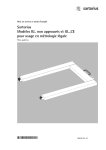
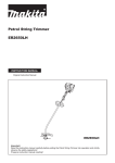
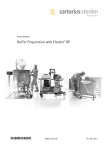
Installation and Operating Instructions
Sartorius
IF.. Standard and IF...CE Verifiable Models
Flat-bed Scale
98648-012-37
General View of the Equipment
2
4
1
3
5
6
1
2
3
4
5
6
2
Weighing platform
Handles|guide bars
Level indicator
Drive-on ramp
Load cell with load-bearing foot
Junction box
Contents
2 General View of the Equipment
3 Intended Use
3 Warnings and Safety Precautions
4 Installation Instructions
4 Installation
6 Connecting the IF.. Flat-bed Scale
8 Care and Maintenance
9 Specifications
9 Accessories (Options)
9 Dimensions (Scale Drawings)
10 Declarations of Conformity
–
–
The following symbols are used in these instructions:
§ indicates required steps
$ indicates steps required only under certain conditions
> describes what happens after you have performed
a particular step
– indicates an item in a list
! indicates a hazard
–
–
Intended Use
The weighing platform is a component of a modular scale,
consisting of the weighing platform and an indicator (which
is comprised of an analog/digital converter and a display and
operator terminal); e.g., a Combics CIS indicator or a QCT01
terminal.
Each component comes with a separate installation and
operating manual.
Note:
The verifiable models (“-.CE”) can be verified for use as a scale
only when connected to a display and control unit/indicator.
Read the installation and operating instructions carefully before
connecting the IF.. weighing platform and putting it into
operation.
For the User
– Always make sure the equipment is disconnected from AC power
before performing any installation, cleaning, maintenance or
repair work on the scale or weighing system.
– If you see any indication that the scale cannot be operated
safely (for example, due to damage), turn it off and lock it in
a secure place or otherwise prevent use of the equipment for the
time being.
Warnings and Safety Precautions
Note:
Improper use or handling can result in damage and|or injury.
The flat-bed scale may be installed and operated by qualified
personnel only. Make sure you observe the warning and safety
information in its entirety during installation and operation,
as well as while performing maintenance and repair work on the
equipment. The standards, regulations, occupational safety
requirements and environmental protection laws valid in your
country must be observed. It is important that all personnel
using the equipment understand this information, and have
access to the relevant documents at all times. Furthermore,
the warning and safety information supplied with any electrical
equipment connected, such as peripheral devices, must be
observed as well. These warnings and safety precautions may
have to be supplemented by the equipment operator. All operating personnel must be informed of any additions to these
instructions. Make sure the equipment is accessible at all times.
General Provisions for Installing IF.. and IF.. CE Models
The IF.. and IF...CE models meet the EC Directives for electromagnetic compatibility and electrical safety.
The IF.. and IF...CE models are not approved for use in hazardous areas, medical facilities, nor areas exposed to potentially
explosive materials. Operating the IF.. and IF...CE models beyond
the restrictions indicated is not permitted, and is considered use
of the equipment for other than its intended purpose. Any installation work that does not conform to the instructions in this
manual will result in forfeiture of all claims under the manufacturer’s warranty.
If the equipment housing is opened by anyone other than persons authorized by Sartorius, this will negate its conformity with
regulations governing its use and result in forfeiture of all claims
under the manufacturer’s warranty.
Installation of the display and control unit/indicator must be
performed by a certified electrician who is familiar with the
assembly, start-up and operation of the system and with the
relevant guidelines and regulations, and has the required qualifications for performing the installation. If you need assistance,
contact your Sartorius dealer or the Sartorius Service Center.
If no interface cable is connected, place a protective cap over the
female interface connector.
–
–
–
–
Note:
If the scale has been verified, the seals affixed to the equipment
indicate that only authorized service technicians are allowed to
open the scale and perform maintenance work, so that safe and
trouble-free operation of the equipment is ensured and the warranty remains in effect. (IF...CE models can be verified for use in
legal metrology only when connected to a display and control
unit/indicator, such as the Combics indicator, isi display and
control unit, or QCT terminal). If any of the verification seals are
damaged, make sure to observe the national regulations and
standards applicable in your country in such cases. In some
countries, the verification becomes null and void and the equipment must be re-verified.
Chemicals (e.g., gases or dusts) that can corrode and damage
the inside or outside of the device must be kept away from the
equipment. Handle the equipment and any accessories in accordance with the IP rating (IP65 or higher) and EN 60529.
The casing on all connecting cables, as well as the casing on
wires inside the equipment housing, is made of PVC. Chemicals
that corrode this material must be kept away from these cables.
The casing of the power cable is made of rubber.
Do not expose the scale to aggressive chemical vapors or to
extreme temperatures, moisture, shocks, or vibration.
The allowable operating temperature range is –10°C to +40°C
(+14°F to +104°F). Make sure the place of installation is adequately ventilated to prevent build-up of excessive heat.
If you use cables purchased from another manufacturer,
check the pin assignments in the cable against those specified
by Sartorius before connecting the cable to Sartorius equipment,
and disconnect any wires that are assigned differently.
The operator shall be solely responsible for any damage or
injuries that occur when using cables not supplied by Sartorius.
Use only genuine Sartorius spare parts.
3
Installation
Instructions
Unpacking the Equipment
§ Please read the enclosed operating
instructions carefully before putting the
scale into operation.
§ After unpacking the equipment, please
check it immediately for any visible
damage.
$ If you detect any damage, proceed as
directed in under “Safety Inspection”
in the chapter entitled “Care and
Maintenance.”
$ It is a good idea to save the box and all
parts of the packaging until you have
successfully installed your equipment.
Only the original packaging provides the
best protection for shipment.
$ Before packing your equipment for shipment, unplug all connected cables to
prevent damage.
Equipment Supplied
– IF.. weighing platform
– Installation and operating instructions
Requirements for the Place of
Installation
§ Observe all safety instructions.
The IF.. scale is designed to provide reliable results under normal ambient conditions. When choosing a location to set
up the IF.., observe the following so that
you will be able to work with added
speed and accuracy:
– Set up the IF.. on a stable, even surface.
The surface directly beneath the scale
should be smooth and dry. The load that
can be carried by the chosen work surface must be sufficient for both the
weighing platform and any load placed
on the platform. Level the scale using
the built-in level indicator.
–
–
–
–
–
When moving the weighing platform, be
sure to observe safety regulations; wear
protective clothing (e.g., hardhat, steeltoed boots, etc.).
Avoid placing the equipment in close
proximity to a heater or otherwise
exposing it to heat or direct sunlight.
Protect the IF.. from direct exposure
to drafts that come from open windows
or doors.
Avoid exposing the IF.. to excessive
vibration.
Protect the IF.. from aggressive
chemical vapors.
Do not expose the equipment to
excessive moisture over long periods.
Turn off the power when the system
is not in use.
Installation
– The allowable operating temperature
range is -10°C to +40°C (+14°F to
+104°F).
– If there is any indication that the
equipment does not function properly
(e.g., display remains blank, or no
display backlighting) due to damage
during transport, disconnect the equipment from power and notify your
nearest Sartorius Service Center; see
also: “Safety Inspection” in the chapter
entitled “Care and Maintenance.”
Shock Resistance
Even though the IF.. scales feature
highly rugged construction, there
are some limits. Avoid exposing the
system to falling objects, side impact,
or shocks.
Notes on Integration into Conveyor
Systems
Any moving or rotating parts intended
to be permanently attached to the
IF.. scale must be designed so that they
cannot affect the weighing results.
For example, rotating mechanisms must
be properly balanced.
The IF.. must be clear on all sides during
weighing so that any dirt or parts that
fall will not create a connection between
the weighing platform and any permanently mounted preload components.
Make sure there are no cables or other
objects exerting force on the load plate.
Avoid generating static electricity.
Using the IF...CE in Legal Metrology
in the EU*
The type-approval certificate for verification applies only to non-automatic
weighing instruments. For automatic
operation with or without auxiliary
measuring devices or equipment, you
must comply with the regulations
applicable to the place of installation.
Conditioning the Weighing System
Moisture in the air can condense on
the surface of a cold weighing instrument or other device whenever it is
brought to a substantially warmer place.
If you transfer the equipment to a
warmer area, make sure to condition it
for about 2 hours at room temperature,
leaving it unplugged from AC power.
Afterwards, if you keep the equipment
connected to AC power, the constant
positive difference in temperature
between the inside of the equipment
and the outside will practically rule out
the effects of moisture condensation.
* including the Signatories of the Agreement
on the European Economic Area
4
Note:
Connection of the scale to a display
and control unit/indicator, installation,
configuration, and putting the equipment into operation must be performed
by a trained dealer or Sartorius service
representative. Details on additional
settings are contained in the Sartorius
service manual.
– Unplug the power cord from the wall
socket (mains) before performing any
work on the equipment.
– The special tools indicated must be used
when performing installation.
– Installation work that affects the IP65
or IP68 protection rating must be performed with extreme care.
– Any installation work that does not conform to the instructions in this manual
will result in forfeiture of all claims
under the manufacturer’s warranty.
– When installing the equipment in
a weighing system, the EU Directive on
Machinery (98/37/EC) must be observed.
– Make sure the junction box and load
cells do not sustain damage.
– Level the scale using the built-in level
indicator.
Note:
Make sure there is a faultless connection
between the display and control unit or
indicator and the platform (resistance:
<1 ohm). The shield must be connected
to the cable gland on the A/D converter
and to the cable gland on the junction
box.
IP Rating
IF.. scales in the galvanized steel version
are rated to IP65; stainless steel versions
have IP68 protection. The levels of protection indicated by these ratings are as
follows:
First digit: rating 6 indicates that the
equipment is dust-tight; i.e., completely
resistant to penetration by solids. Second digit: rating 5 indicates resistance
to penetration by water, including powerful jets of water; rating 8 indicates
resistance to ingress of water during
complete, continuous submersion in
water to a depth of up to 10 meters
(approx. 32 feet).
IP65 or IP68 protection is guaranteed
only if:
– the seals on the junction box are
installed correctly in accordance with
industry standards, and
– the connecting cables, protective caps
and cable glands were installed and
connected by a qualified technician.
Affixing Equipment Designation Labels to the IF...CE
Equipment designation labels that correspond to configuration
of the scale must be affixed to the equipment prior to initial
verification. To do this, affix the labels to the display and control
unit/indicator or, in special cases, to the plates provided. If
plates are required, they are included in the equipment supplied
with the display and control unit/indicator. Fasten the plate to
the connecting cable between the IF...CE and the display and
control unit/indicator.
§ Affix the label to the plate.
Connecting the Scale to AC Power
The IF.. scale is powered over the connecting cable from the
display and control unit/indicator.
Floor-mounting the IF (Option T8)
§ Remove the floor-mounting bracket
from the packaging (included when
Option T8 is ordered).
§ Position the equipment at the
desired place of installation.
$ Align the stainless steel plates so
that they are parallel.
§ Mark the positions for drilling
the required holes, using the floormounting bracket as a template.
§ Drill pilot holes using your markings
as a guide.
§ Move the bracket and flat-bed scale
out of the way and drill the holes for
the floor-mounting bracket.
§ Clean the surface thoroughly.
§ Position the scale over the holes
and affix it in place with the
floor-mounting bracket.
$ Make sure to avoid putting strain
on any part of the equipment!
Transporting the IF (Option T7)
§ Make sure there is no load on the
scale.
§ Remove the drive-on ramp from the
front of the scale.
$ Make sure to observe the safety
instructions.
§ Remove the threaded caps from
the four threaded fasteners and keep
them in a safe place.
§ Attach the two hand cranks to
the two threaded fasteners at the
front of the scale.
§ Turn the cranks clockwise to lower
the transport rollers.
$ Repeat this procedure for the
two rear rollers.
§ The scale can now be moved into
the desired position.
§ If available, fasten the towing bar
(optional) as shown.
§ The scale can now be pulled into
the desired position.
$ This procedure is useful, for example, for cleaning the surface beneath
the scale at the place of installation.
§ Return the weighing platform to
the place of installation and retract
the rollers.
§ Remove the hand crank and replace
the four threaded caps.
§ Fasten the drive-on ramp to the
front of the scale.
$ Make sure to observe the safety
instructions.
5
Connecting the IF.. Flat-bed Scale
Connecting Cable: IF.. to Display and Control Unit or Indicator
V+
Sense +
Signal +
Signal –
Sense –
V–
Ground
6
(Supply voltage +)
(Supply voltage –)
(Output signal +)
(Output signal –)
(Shield +)
(Shield –)
(Shield)
Cable: type A
(white)
(brown)
(green)
(yellow)
(pink)
(gray)
or
or
or
or
or
or
or
Cable: type B
blue
black
white
red
green
gray
The IF.. Weighing Platforms
Example of model designation:
IF P
P=
Painted
steel
S=
Stainless
steel
4
1500
RR -LCE
Weighing
capacity in kg
Resolution, not verifiable:
15,000 d = L, 30,000 d = I
Verifiable:
3000 e = LCE, 2 +3000 e = NCE
Dimensions
Load cells
150
50
300
600
1000
000
1500
500
3000
The IF.. Weighing Platforms
Galvanized models:
– Weighing capacities from 150 kg
to 3000 kg
– 11 different sizes
– 6 weighing capacities
– 59 models
– 3000 e, 2+3000 e Cl. III (depends on
model); 15,000 d, 30,000 d
– Surface finishing: painted
– IP65 rating
– Drive-on ramp
– Customized versions possible
GG
600 + 600
IG
800 + 600
II
800 + 800
LG
1000 + 600
LI
1000 + 800
LL
1000 + 1000
NL
1250 + 1000
NN
1250 + 1250
Stainless steel models:
– Weighing capacities from 150 kg
to 3000 kg
– 11 different sizes
– 6 weighing capacities
– 59 models
– 3000 e, 2+3000 e Cl. III (depends on
model); 15,000 d, 30,000 d
– Material/surface finishing:
AISI 304 or AISI 316 Ti stainless steel,
brushed or electropolished
– IP67/IP65 rating
– Stainless steel load cells
– Drive-on ramp; customized versions
possible
RN
1500 + 1250
RR
1500 + 1500
WR
2000 + 1500
7
Care and Maintenance
Service
Regular servicing by a Sartorius technician will extend the
service life of your IF.. scale or weighing system and help to
ensure its continued weighing accuracy. Sartorius can offer
you service contracts, with your choice of regular maintenance
intervals ranging from 1 month to 2 years.
§ Unlock the load plate from the
vertical position, use the handle
to lower the load plate, and secure
the safety catches on the right
and left.
Repairs
! Disconnect defective equipment from power immediately. Repairs
may be performed only by authorized Sartorius service technicians
using genuine Sartorius parts. Any attempt by untrained persons
to perform repairs may result in considerable hazards for the user.
! If a cable or cable gland is damaged or defective, replace the
cable as a complete unit with all its connectors.
Cleaning
! Always handle the equipment in keeping with its IP protection
rating. Make sure that no liquid enters the IF.. housing.
$ Unplug the system from power before cleaning or performing
maintenance or repair work. Clean the system regularly to remove
all impurities.
$ Avoid generating static electricity. Devices rated to IP65 can be rinsed down with a jet of water that strikes the load plate from above.
! When using high-pressure cleaning equipment to clean the IF..
scale, do not point the jet of steam directly at the load cells.
> If the water that you use to clean the scale is too hot or too cold,
the difference in temperature between the water and the scale
can cause condensation inside the scale housing.
This condensation can lead to malfunctions in the equipment.
Cleaning Beneath the Load Plate (Option T8)
Important Note:
The load plate must be locked into the vertical position or held
in this position by a second person.
Warning: Danger of personal injury! Make sure to observe all
warnings and the safety precautions. All personnel must wear
steel-toed boots while performing work that involves lifting
or raising the load plate.
§ Use the foot switches on the right
and left and lower the safety
catch.
§ Use the handle to lift the front
of the load plate upwards.
Observe all warnings and safety
precautions!
Important: Lock the load plate
into the vertical position.
§ Clean the area beneath the load
plate.
8
Cleaning Stainless Steel Surfaces
Clean all stainless steel parts regularly. Use a damp cloth or
sponge to clean any stainless steel parts on the system. You can
use any commercially available household cleaning agent that
is suitable for use on stainless steel. Clean stainless steel surfaces
by wiping them down. Then rinse the equipment thoroughly,
making sure to remove all residues. Wipe down stainless steel
parts again using a clean, damp cloth or sponge. Afterwards,
allow the equipment to dry. If desired, you can apply oil to the
cleaned surfaces as additional protection.
! Do not use stainless steel cleaning agents that contain soda lye
(caustic), acetic acid, hydrochloric acid, sulfuric acid or citric acid.
The use of scrubbing sponges made with steel wool is not permitted. Solvents are permitted only for cleaning stainless steel parts.
Corrosive Environment
$ Remove all traces of corrosive substances on a regular basis.
Safety Inspection
If there is any indication that safe operation of the IF.. is no
longer warranted; i.e.:
– If there is visible damage to the connecting cable,
– If the device no longer functions properly,
– If the equipment has been stored for a relatively long period
under unfavorable conditions, or
– If the equipment has been subjected to rough handling during
shipment,
§ make sure all safety instructions are observed, and notify your
nearest Sartorius Service Center or the International Technical
Support Unit based in Goettingen, Germany. Maintenance and
repair work may be performed only by authorized Sartorius
service technicians who have access to the required maintenance
manuals and have received the necessary training.
! The seals affixed to this equipment indicate that only authorized
service technicians are allowed to open the equipment and perform maintenance work so that safe and trouble-free operation
of the equipment is ensured and the warranty remains in effect.
Storage and Shipping Conditions
$ The packaging used for shipping your Sartorius equipment
is optimally designed to prevent damage during transport. It
is a good idea to save the box and all parts of the packaging for
future storage or shipment of the equipment. Only the original
packaging provides the best protection for shipment.
$ Allowable storage temperature: –20°C to +75°C (–4°F to +167°F)
$ Allowable humidity during storage: max. 90%
$ Please refer to the information under “Warnings and Safety
Precautions.”
Instructions for Recycling
If you no longer need the packaging after successful installation
of the equipment, you should return it for recycling. The packaging is made from environmentally friendly materials and is
a valuable source of secondary raw material. Contact your local
waste disposal authorities if you wish to scrap the equipment.
Sartorius AG in Goettingen will take back equipment and packaging for disposal in accordance with the applicable laws.*
If you set up the equipment in a country other than Germany,
please contact your local waste disposal authorities for information on similar services.
* This service is offered only within Germany
Specifications
General Specifications for the IF-... Models
Model
IF..
Allowable ambient operating temperature
°C
–10 to +40 (+14°F to +104°F)
IP rating
IP65
IP68
(painted models)
(stainless steel models)
The cables supplied with the weighing platforms as standard equipment are 6 m in length.
Capacities: Up to 3000 kg, with restrictions, when the load is distributed on the load plate.
Accessories (Options)
Order no.
Additional drive-on ramps
available on request
Frame for pit installation
available on request
For affixing the weighing platform to the floor:
Floor-mounting set
YFP01I
Columns can be manufactured to order on request.
Dimensions
D
W
Designation
GG
IG
II
LG
LI
LL
NL
NN
RN
RR
WR
D (mm)
600
800
800
1,000
1,000
1,000
1,250
1,250
1,500
1,500
2,000
W (mm)
600
600
800
600
800
1,000
1,000
1,250
1,250
1,500
1,500
Resolutions
Resolution 1
weighing capacity: -L
-l
-LCE
Resolution 2
weighing capacities -NCE
2 +3,000e
Resolution:
Capacity 1
in g
Weighing
capacity 2
in kg
Resolution:
Capacity 2
in g
Weighing
capacity
in kg
15,000d
in g
30,000d
in g
1+ 3,000e
in g
Weighing
capacity 1
in kg
150
10
5
50
60
20
150
50
300
20
10
100
150
50
300
100
600
50
20
200
300
100
600
200
1000
100
50
500
600
200
1,000
500
1500
100
50
500
600
200
1,500
500
3000
200
100
1,000
1,500
500
3,000
1,000
9
Declarations of Conformity
The C marking may be affixed only
to equipment that complies with the
following Directives (below). Conformity
has been tested in conjunction with
Sartorius equipment:
Council Directive 89/336/EEC
“Electromagnetic compatibility (EMC)”
as amended by 93/68/EEC
Applicable European Standards:
1.1 Reference to 89/336/EEC:
Official Journal of the European
Communities, No. 2001/C105/03
EN 61326-1 Electrical equipment
for measurement,
control and laboratory
use EMC requirements
Part 1:
General requirements
Defined immunity
to interference:
Industrial areas,
continuous, un-monitored operation
Limitation of emissions:
Residential areas,
IF....
Class A
Note:
The operator shall be responsible for
any modifications to the indicator and
for any connections of cables or equipment not supplied by Sartorius.
On request, Sartorius will provide
information on the minimum operating
specifications (in accordance with the
Standards listed above for defined
immunity to interference).
10
73/23/EEC “Electrical equipment
designed for use within certain voltage
limits” as amended by 93/68/EEC
Applicable European Standards:
EN 60950 Safety of information
technology equipment
including electrical business
equipment
EN 61010 Safety requirements for
electrical equipment for
measurement, control
and laboratory use
Part 1:
General requirements
Weighing Instruments for Use
in Legal Metrology: Council Directive
90/384/EEC “Non-automatic weighing
instruments”
This Directive regulates the determination of mass in legal metrology.
For the respective Declaration of Type
Conformity for Sartorius weighing
instruments verified for use as legal
measuring instruments that have an
EC Type-Approval Certificate, see
“Declaration of Conformity” in the
instruction manual for the connected
display and control unit/indicator. This
Directive also regulates EC verification
by the manufacturer, provided that an
EC Type-Approval Certificate has been
issued and the manufacturer has been
accredited by an officer of a Notified
Body registered at the Commission of
the European Community for performing such verification. The legal basis
for EC verification is EC Directive No.
90/384/EEC for non-automatic weighing instruments, which has been in
effect since January 1, 1993, within
the Single European Market, and the
accreditation of the Quality Management System of Sartorius AG by Lower
Saxony’s Regional Administrative
Department of Legal Metrology (Niedersächsische Landesverwaltungsamt –
Eichwesen) from February 15, 1993.
“EC Verification” –
A Service Offered by Sartorius
Our service technicians authorized to
perform the verification of your weighing instruments that are acceptable
for legal metrological verification can
inspect and verify the metrological
specifications at the place of installation within the Member States of the
European Union and the Signatories
of the Agreement on the European
Economic Area.
Subsequent Verifications within the
European Countries
The validity of the verification will
become void in accordance with the
national regulations of the country in
which the weighing instrument is used.
For information on verification and
legal regulations currently applicable in
your country, and to obtain the names
of the persons to contact, please contact your local Sartorius office, dealer
or service center.
11
12
13
14
15
16
17
18
Sartorius AG
Weender Landstrasse 94–108
37075 Goettingen, Germany
Phone +49.551.308.0
Fax +49.551.308.3289
www.sartorius.com
Copyright by Sartorius AG,
Goettingen, Germany.
All rights reserved. No part
of this publication may
be reprinted or translated in
any form or by any means
without the prior written
permission of Sartorius AG.
The status of the information,
specifications and illustrations
in this manual is indicated
by the date given below.
Sartorius AG reserves the
right to make changes to
the technology, features,
specifications and design of
the equipment without notice.
Status:
November 2004, Sartorius AG,
Goettingen, Germany
Printed in Germany on paper that has been bleached
without any use of chlorine
W6A000 · ZPD · KT
Publication No.: WIF6002-e04112